
ari safety valve manual supplier

ARI can look back on a tradition of more than sixty years as a partner for control, isolation, safety and steam trapping of liquid and gaseous media. Are you looking for product solutions specially tailored to your individual requirements? Profit from our "one-stop shop" philosophy.
We specialize in thermal heat transfer fluid (hot oil) valves, known in the ARI-Armaturen family as the FABA product line. These are commonly found anywhere heat transfer is required whether for the manufacture of engineered wood, chemicals, automobiles, coatings, fibers and non-woven textiles, asphalt, industrial cooking, and a host of other industries. Other ARI-Armaturen products are found in similar applications and industries, and we can assist you with these as well.
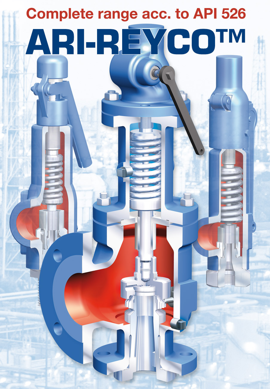
Direct Loaded Safety Valves for blowing off excess pressure of steam, vapor, gases, and liquid from pressure vessels, steam boiler, hot water boiler and piping systems. ARI-SAFE safety valves are available in full-stroke and normal versions.
Our safety valves are available with metal or soft seated plugs, with precise centering and guiding. Materials include cast iron, cast steel, and stainless steel. Call us for further options!

ARI can look back on a tradition of more than seventy years as a partner for control, isolation, safety and steam trapping of liquid and gaseous media. Are you looking for product solutions specially tailored to your individual requirements? Profit from our "one-stop shop" philosophy.

ISO 9001 certified distributor of valves including bellow seal, DIN/ANSI control, safety, pressure regulating, reducing, strainers, check, butterfly, flow regulatory, manual and actuated valves and steam traps. Applications include isolating, securing and regulating thermal oil, feed water, hot and cold fluids, vapor, chemicals, gases and steam. Steam traps include ball float, bimetallic, thermostatic and thermodynamic. Control valves available with electric and pneumatic actuators. Safety valves available in full-stroke and normal versions. Materials include stainless, cast, and forged steel, and cast iron. Actuators include diaphragm, electric, pneumatic and manual. Valve applications include car manufacturing, ships, chemicals, food processing, industrial installation, powerstations, fuel/gas purification plant, gas supply, heating, cooling, freezing, and steam systems, and processing technology. Meets ANSI and European pressure ratings.
ARI products are in service around the globe. Whether it is manufacturing cars, ships, chemicals, food processing or heating technology, you will find ARI where any fluid, liquid, gas or vapor needs to be isolated, secured or regulated. As a perennial member of more than 30 representatives on all continents around the globe, we can provide you with the advantages of a reliable partnership wherever you are.

Manufacturer of valves for gas, liquid, and steam applications. Products include control valves, pressure control, temperature control, globe valves, butterfly valves, check valves, safety relief valves, changeover valves, steam traps, pump traps, mechanical condensate pumps, collection & distribution manifolds, strainers, vacuum breakers, and complete engineered systems. Control valves available in electric or pneumatic configurations. Actuators include diaphragm, electric, pneumatic, and manual. Globe valves available with gland or bellows sealing. Butterfly valves in soft sealing, double-offset, and triple-offset configurations. Safety relief valves available in semi-nozzle or full-nozzle design. Steam traps include float & thermostatic, thermodynamic disc, bimetallic, and thermostatic, in standard configurations, with All-in-One Multi-Valving technology, or with Universal Connections. Markets include food & beverage, powerplants & renewable energy, steelworks & metallurgy, wood/pulp/paper, tires, refrigeration, oil & gas, plant engineering, shipbuilding, and HVAC. Valve applications include the isolation, securing, and regulating of thermal oil, feed water, hot & cold fluids, hydrogen, chemicals, alcohols & polymers, vapor, gases, and steam. Meets ANSI and European pressure ratings. Certified to ISO 9001:2015, ASME Boiler & Pressure Vessel (BPVC), National Board UV & VR, PED (2014/68/EU), CRN, and others.
ARI-Armaturen can look back on a tradition of more than 60 years as a specialist for valves & components. In 2002, ARI-Armaturen USA was established in Houston, Texas to provide a growing North American customer base with localized support and inventory.
From industrial processes and chemicals through shipbuilding to building management, whether standard constructions or custom-made, our broad product portfolio of industrial valves and services linked to control, isolation, safety, and steam trapping always provide the best solutions. Product development, manufacturing, and rigorous testings are always done with state-of-the-art technologies and quality control processes.

ARI-SAFE Safety valve Full lift safety valve / Standard safety valve ARI-SAFE Full lift safety valve D/G Standard safety valve F • Type-test approved acc. to DIN EN ISO 4126 / AD2000-A2 • TÜV · SV · . . -663 · D/G Figure 901-912 • TÜV · SV · . . -663 · F Figure 901/911 • Further approvals: see inside ARI-SAFE Standard safety valve for the heating technology • Type-test approved acc. to TRD 721 • TÜV · SV · . . -688 · D/G/H Figure 903 • TÜV · SV · . . -688 · D Figure 904 ARI-SAFE-P Standard safety valve D/G/F • Type-test approved acc. to DIN EN ISO 4126 / AD2000-A2 • TÜV · SV · . . -811 · D/G Figure 921-924 • TÜV · SV · . . -811 · F Figure 921/923 ARI-SAFE-TC Full lift safety valve D/G Standard safety valve F • Type-test approved acc. to DIN EN ISO 4126 / AD2000-A2 • TÜV · SV · . . -995 · D/G Figure 941-943 • TÜV · SV · . . -995 · F Figure 941/943 ARI-SAFE-TC Standard safety valve for the heating technology • Type-test approved acc. to TRD 721 • TÜV · SV · . . -997 · D/G/H Figure 945 • TÜV · SV · . . -997 · D Figure 946 ARI-SAFE-TCP Standard safety valve D/G/F • Type-test approved acc. to DIN EN ISO 4126 / AD2000-A2 • TÜV · SV · . . -1041 · D/G Figure 961-963 • TÜV · SV · . . -1041 · F Figure 961/963 ARI-SAFE-TCS Standard safety valve D/G/F • Type-test approved acc. to DIN EN ISO 4126 / AD2000-A2 • TÜV · SV · . . -1041 · D/G Figure 951-953 • TÜV · SV · . . -1041 · F Figure 951/953 FOR HORIZONTAL APPLICATION Edition 11/12 - Data subject to alteration Features: • Direct loaded with spring • Wear resistant seat/disc • Precision disc alignment and guide • Possible with soft seal disc • Possible with EPDM bellow 953 • Possible with stainless steel bellow Page 28 • ARI-SAFE-TC/TCP/TCS: All common thread types Data sheet 900001 englisch (english)
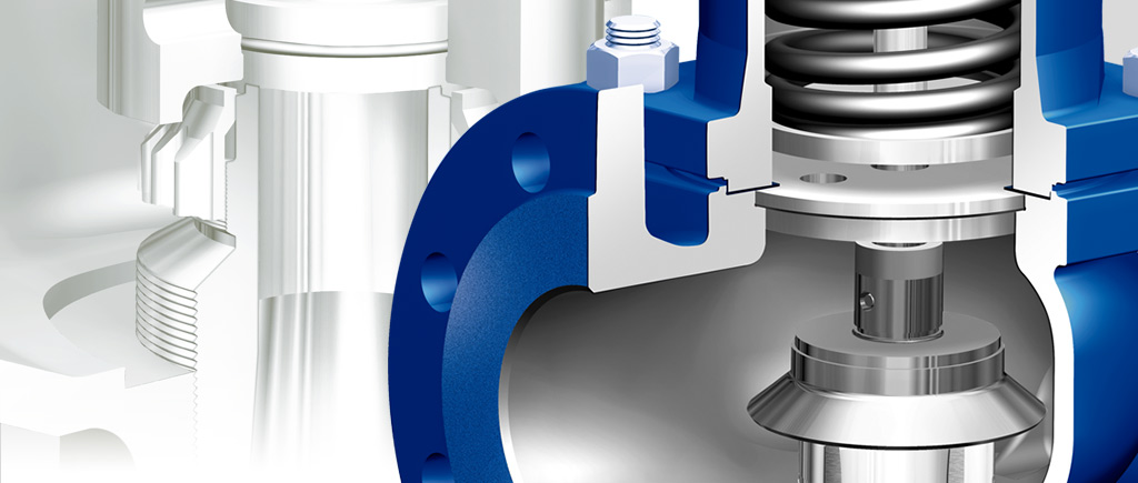
Fig. 901 / 902 / 911 / 912 ARI-SAFE - Full lift safety valve D/G, Standard safety valve F Figure Nominal pressure Nominal diameter Temperature range Flange holes/thickness tolerances DIN 2533/2533 DIN 28607/28605 DIN 2545/2543 DIN 2545/2543 Type-test approval Full lift safety valve: TÜV · SV · . . -663 · D/G (Fig. 901/902/911/912) Standard safety valve: TÜV · SV · . . -663 · F (Fig. 901/911) Set gauge pressure refer to „Capacity“. Requirement Acc. to EN ISO 4126-1, VdTÜV-leaflet 100, AD2000-A2, TRD 421, material selection observe TRB 801 No. 45!! Construction Safety valve, spring loaded,...
Fig. 901 / 902 / 911 / 912 Dimensions and weights DN1/DN2 (mm) 20/32 18 d0 (mm) 254 A0 (mm2) 85 l (mm) 95 l1 (mm) 270 H (mm) 310 H (Bellow design) (mm) 150 X (mm) G 1/4“ Drainhole with plug 1) (inch) 8,5 Weight (kg) 9,5 Weight (Bellow design) (kg) Standard-flange dimensions refer to page 34. 1) Spring ranges: Standard design (barg) DN20 DN25 - 50 DN65 DN80 Spring ranges: Bellow design (barg) DN20 DN25 DN32 DN40 Design with bellow as standard valve (only Fig. 901/911) Description Body Seat Studs Spindle guide Hexagon nut Bonnet, closed 12 Disc unit 14 Spindle * 17 Adjusting screw 28 Cap,...
Capacity Fig. 901 / 911 Capacity water incl. 10% overpressure Gauge press. ← max. set pressure stainless steel version Certified coefficient of discharge Kdr (Values for D/G variable: DN20-100 < 3,5 bar, DN125-150 < 4,0 bar) Kdr D/G Edition 11/12 - Data subject to alteration
ARI-SAFE - Heating-safety valve Figure Nominal pressure Nominal diameter Temperature range Flange holes/thickness tolerances DIN 2533/2533 Type-test approval spring loaded: TÜV · SV · . . -688 · D/G/H Set gauge pressure refer to „Capacity“. Requirement Acc. to TRD 721 Part 6, material selection observe TRD! (EN-JL1040 max. 10 bar; >10 bar 25.903 EN-JS1049 or 35.903 1.0619+N) Application Acc. to DIN EN 12828 Heating systems in buildings Constructions Standard safety valve, spring loaded, direct loaded metal seat with EPDM insert, EPDM-bellow, closed spring bonnet with control hole, open...
Dimensions and weights DN1/DN2 (mm) 20/32 18 d0 (mm) 254 A0 (mm2) 85 l (mm) 95 l1 (mm) 270 H (mm) 150 X (mm) G 1/4“ Drainhole with plug (optional) (inch) 8,5 Weight (kg) Standard-flange dimensions refer to page 34. Parts Pos. Description 1 Body 2 Seat 3 Studs 4 Spindle guide 8 Hexagon nut 11 Bonnet, closed 12 Disc unit 14 Spindle * 17 Adjusting screw 29 Cap, open 37 Spring * 41 Lever, open 43 Bellow * Spare parts Information / restriction of technical rules need to be observed! ARI-Valves of EN-JL1040 are not allowed to be operated in systems acc. to TRD 110. A production allowance acc. to...
Capacity Fig. 903 Capacity water Water 20°C (kg/h) ^ Sizing: 1 l/h = 1 kW Sizing safety valves for the volume flow of water expansion (DIN 4751 p2 - item 8.1) Edition 11/12 - Data subject to alteration
ARI-SAFE - Low pressure steam - safety valve Figure Nominal pressure Nominal diameter Temperature range Flange holes/thickness tolerances DIN 2533/2533 Type-test approval Low pressure steam - safety valve: TÜV · SV · . . -688 · D Set gauge pressure refer to „Capacity“. Requirement Acc. to TRD 721 Part 5 Application For low pressure steamgenerators up to 1 bar, DIN 4750 and DIN EN 12828 Heating systems in buildings Construction Standard safety valve, spring loaded, direct loaded, EPDM-bellow, closed bonnet with control hole, open lifting device, stainless steel seat and spindle Sizing refer...
Valves Online Limited is a company registered in England. Registration number: 04994458. Registered office: Unit L3 Yelverton Business Park, Crapstone, Yelverton, Devon, United Kingdom, PL20 7PY.

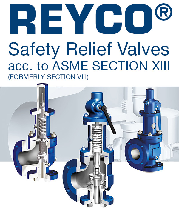
The ARI-REYCO line from ARI Armaturen features a range of direct spring acting safety relief valves for gas, liquid, and steam service. As a distributor for ARI-Armaturen, Cross company offers a variety of options to keep your operation safe and our team of experts have worked with customers in a wide range of process applications across multiple industries.
With such a variety of options available, finding the right solution is important. We can work with your team to determine the best product for your operation. Learn more about ARI-REYCO series safety relief valves below and Start a conversation with a Cross expert today!
*ARI-REYCO brand valves (and/or valve parts) are fully interchangeable with, and replaceable for, Lonergan valves (and/or valve parts). Londergan is a trademark of Pentair Valves and Controls. ARI-Reyco is not licensed to use the Lonergan trademark.
Safety valves are precision items of safety equipment; they are set to close tolerances and have accurately machined internal parts. They are susceptible to misalignment and damage if mishandled or incorrectly installed.
Valves should be transported upright if possible and they should never be carried or lifted by the easing lever. In addition, the protective plugs and flange protectors should not be removed until actual installation. Care should also be taken during movement of the valve to avoid subjecting it to excessive shock as this can result in considerable internal damage or misalignment.
When designing the inlet pipework, one of the main considerations is to ensure that the pressure drop in this pipework is minimised. EN ISO 4126 recommends that the pressure drop be kept below 3% of the set pressure when discharging. Where safety valves are connected using short ‘stub’ connections, inlet pipework must be at least the same size as the safety valve inlet connection. For larger lines or any line incorporating bends or elbows, the branch connection should be at least two pipe sizes larger than the safety valve inlet connection, at which point it is reduced in size to the safety valve inlet size (see Figure 9.5.5a). Excessive pressure loss can lead to ‘chatter’, which may result in reduced capacity and damage to the seating faces and other parts of the valve. In order to reduce the pressure loss in the inlet, the following methods can be adopted:
Safety valves should always be installed with the bonnet vertically upwards. Installing the valve in any other orientation can affect the performance characteristics.
The API Recommended Practice 520 guidelines also state that the safety valve should not be installed at the end of a long horizontal pipe that does not normally have flow through it. This can lead to the accumulation of foreign material or condensate in the pipe, which may cause unnecessary damage to the valve, or interfere with its operation.
There are two possible types of discharge system – open and closed. An open system discharges directly into the atmosphere whereas a closed system discharges into a manifold along with other safety valves.
It is recommended that discharge pipework should rise for steam and gas systems, whereas for liquids, it should fall. Horizontal pipework should have a downward gradient of at least 1 in 100 away from the valve ensuring that any discharge will be self-draining. It is important to drain any rising discharge pipework. Vertical rises will require separate drainage. Note: all points of system drainage are subject to the same precautions, notably that valve performance must not be affected, and any fluid must be discharged to a safe location.
It is essential to ensure that fluid cannot collect on the downstream side of a safety valve, as this will impair its performance and cause corrosion of the spring and internal parts. Many safety valves are provided with a body drain connection, if this is not used or not provided, then a small bore drain should be fitted in close proximity to the valve outlet (see Figure 9.5.3).
One of the main concerns in closed systems is the pressure drop or built-up backpressure in the discharge system. As mentioned in Module 9.2, this can drastically affect the performance of a safety valve. The EN ISO 4126: Part 1 standard states that the pressure drop should be maintained below 10% of the set pressure. In order to achieve this, the discharge pipe can be sized using Equation 9.5.1.
Calculate the nominal diameter of the discharge pipework for a safety valve required to discharge 1 000 kg/h of saturated steam; given that the steam is to be discharged into a vented tank via the pipework, which has an equivalent length of 25 m. The set pressure of the safety valve is 10 bar g and the acceptable backpressure is 10% of the set pressure. (Assume zero pressure drop along the tank vent).
Therefore, the pipework connected to the outlet of the safety valve should have an internal diameter of at least 54 mm. With schedule 40 pipe, this would require a DN65 pipe.
Balanced safety valves require that their bonnets be vented to atmosphere. In the case of the balanced bellows type, there will be no discharge of the process fluid, so they can be vented directly to the atmosphere. The main design consideration is to ensure that this vent will not become blocked, for example, by foreign material or ice. With the balanced piston type, consideration must be given to the fact that process fluid may be discharged through the bonnet vent. If discharging to a pressurised system, the vent has to be suitably sized, so that no backpressure exists above the piston.
Safety valves that are installed outside of a building for discharge directly into the atmosphere should be covered using a hood. The hood allows the discharge of the fluid, but prevents the build up of dirt and other debris in the discharge pipework, which could affect the backpressure. The hood should also be designed so that it too does not affect the backpressure.
Manifolds must be sized so that in the worst case (i.e. when all the manifold valves are discharging), the pipework is large enough to cope without generating unacceptable levels of backpressure. The volume of the manifold should ideally be increased as each valve outlet enters it, and these connections should enter the manifold at an angle of no greater than 45° to the direction of flow (see Figure 9.5.6). The manifold must also be properly secured and drained where necessary.
In open systems, careful consideration must be given to the effects of the reaction forces generated in the discharge system when the valve lifts. In these systems, there will be significant resultant force acting in the opposite direction to that of discharge. It is important to prevent excessive loads being imposed on the valve or the inlet connection by these reaction forces, as they can cause damage to the inlet pipework. The magnitude of the reaction forces can be calculated using the formula in Equation 9.5.2:
The reaction forces are typically small for safety valves with a nominal diameter of less than 75 mm, but safety valves larger than this usually have mounting flanges for a reaction bar on the body to allow the valve to be secured.
Regardless of the magnitude of the reaction forces, the safety valve itself should never be relied upon to support the discharge pipework itself and a support should be provided to resist the weight of the discharge pipework. This support should be located as close as possible to the centreline of the vent pipe (see Figure 9.5.7).
Changeover valves (see Figure 9.5.10) permit two valves to be mounted side by side, with one in service and one isolated. This means regular maintenance can be carried out without interruption of service or the vessel being protected. Changeover valves are designed in such a way that when they are operated, the pass area is never restricted.
Changeover valves can also be used to connect safety valve outlets so that the discharge pipework does not have to be duplicated. The action of both inlet and outlet changeover valves has to be limited and synchronised for safety reasons. This is usually by means of a chain drive system linking both handwheels.
Consideration must be made to pressure loss caused by the changeover valve when establishing the safety valve inlet pressure drop, which should be limited to 3% of the set pressure.


 8613371530291