
ari safety valve manual price

Valves Online Limited is a company registered in England. Registration number: 04994458. Registered office: Unit L3 Yelverton Business Park, Crapstone, Yelverton, Devon, United Kingdom, PL20 7PY.

ARI-SAFE Safety valve Full lift safety valve / Standard safety valve ARI-SAFE Full lift safety valve D/G Standard safety valve F • Type-test approved acc. to DIN EN ISO 4126 / AD2000-A2 • TÜV · SV · . . -663 · D/G Figure 901-912 • TÜV · SV · . . -663 · F Figure 901/911 • Further approvals: see inside ARI-SAFE Standard safety valve for the heating technology • Type-test approved acc. to TRD 721 • TÜV · SV · . . -688 · D/G/H Figure 903 • TÜV · SV · . . -688 · D Figure 904 ARI-SAFE-P Standard safety valve D/G/F • Type-test approved acc. to DIN EN ISO 4126 / AD2000-A2 • TÜV · SV · . . -811 · D/G Figure 921-924 • TÜV · SV · . . -811 · F Figure 921/923 ARI-SAFE-TC Full lift safety valve D/G Standard safety valve F • Type-test approved acc. to DIN EN ISO 4126 / AD2000-A2 • TÜV · SV · . . -995 · D/G Figure 941-943 • TÜV · SV · . . -995 · F Figure 941/943 ARI-SAFE-TC Standard safety valve for the heating technology • Type-test approved acc. to TRD 721 • TÜV · SV · . . -997 · D/G/H Figure 945 • TÜV · SV · . . -997 · D Figure 946 ARI-SAFE-TCP Standard safety valve D/G/F • Type-test approved acc. to DIN EN ISO 4126 / AD2000-A2 • TÜV · SV · . . -1041 · D/G Figure 961-963 • TÜV · SV · . . -1041 · F Figure 961/963 ARI-SAFE-TCS Standard safety valve D/G/F • Type-test approved acc. to DIN EN ISO 4126 / AD2000-A2 • TÜV · SV · . . -1041 · D/G Figure 951-953 • TÜV · SV · . . -1041 · F Figure 951/953 FOR HORIZONTAL APPLICATION Edition 11/12 - Data subject to alteration Features: • Direct loaded with spring • Wear resistant seat/disc • Precision disc alignment and guide • Possible with soft seal disc • Possible with EPDM bellow 953 • Possible with stainless steel bellow Page 28 • ARI-SAFE-TC/TCP/TCS: All common thread types Data sheet 900001 englisch (english)
Fig. 901 / 902 / 911 / 912 ARI-SAFE - Full lift safety valve D/G, Standard safety valve F Figure Nominal pressure Nominal diameter Temperature range Flange holes/thickness tolerances DIN 2533/2533 DIN 28607/28605 DIN 2545/2543 DIN 2545/2543 Type-test approval Full lift safety valve: TÜV · SV · . . -663 · D/G (Fig. 901/902/911/912) Standard safety valve: TÜV · SV · . . -663 · F (Fig. 901/911) Set gauge pressure refer to „Capacity“. Requirement Acc. to EN ISO 4126-1, VdTÜV-leaflet 100, AD2000-A2, TRD 421, material selection observe TRB 801 No. 45!! Construction Safety valve, spring loaded,...
Fig. 901 / 902 / 911 / 912 Dimensions and weights DN1/DN2 (mm) 20/32 18 d0 (mm) 254 A0 (mm2) 85 l (mm) 95 l1 (mm) 270 H (mm) 310 H (Bellow design) (mm) 150 X (mm) G 1/4“ Drainhole with plug 1) (inch) 8,5 Weight (kg) 9,5 Weight (Bellow design) (kg) Standard-flange dimensions refer to page 34. 1) Spring ranges: Standard design (barg) DN20 DN25 - 50 DN65 DN80 Spring ranges: Bellow design (barg) DN20 DN25 DN32 DN40 Design with bellow as standard valve (only Fig. 901/911) Description Body Seat Studs Spindle guide Hexagon nut Bonnet, closed 12 Disc unit 14 Spindle * 17 Adjusting screw 28 Cap,...
Capacity Fig. 901 / 911 Capacity water incl. 10% overpressure Gauge press. ← max. set pressure stainless steel version Certified coefficient of discharge Kdr (Values for D/G variable: DN20-100 < 3,5 bar, DN125-150 < 4,0 bar) Kdr D/G Edition 11/12 - Data subject to alteration
ARI-SAFE - Heating-safety valve Figure Nominal pressure Nominal diameter Temperature range Flange holes/thickness tolerances DIN 2533/2533 Type-test approval spring loaded: TÜV · SV · . . -688 · D/G/H Set gauge pressure refer to „Capacity“. Requirement Acc. to TRD 721 Part 6, material selection observe TRD! (EN-JL1040 max. 10 bar; >10 bar 25.903 EN-JS1049 or 35.903 1.0619+N) Application Acc. to DIN EN 12828 Heating systems in buildings Constructions Standard safety valve, spring loaded, direct loaded metal seat with EPDM insert, EPDM-bellow, closed spring bonnet with control hole, open...
Dimensions and weights DN1/DN2 (mm) 20/32 18 d0 (mm) 254 A0 (mm2) 85 l (mm) 95 l1 (mm) 270 H (mm) 150 X (mm) G 1/4“ Drainhole with plug (optional) (inch) 8,5 Weight (kg) Standard-flange dimensions refer to page 34. Parts Pos. Description 1 Body 2 Seat 3 Studs 4 Spindle guide 8 Hexagon nut 11 Bonnet, closed 12 Disc unit 14 Spindle * 17 Adjusting screw 29 Cap, open 37 Spring * 41 Lever, open 43 Bellow * Spare parts Information / restriction of technical rules need to be observed! ARI-Valves of EN-JL1040 are not allowed to be operated in systems acc. to TRD 110. A production allowance acc. to...
Capacity Fig. 903 Capacity water Water 20°C (kg/h) ^ Sizing: 1 l/h = 1 kW Sizing safety valves for the volume flow of water expansion (DIN 4751 p2 - item 8.1) Edition 11/12 - Data subject to alteration
ARI-SAFE - Low pressure steam - safety valve Figure Nominal pressure Nominal diameter Temperature range Flange holes/thickness tolerances DIN 2533/2533 Type-test approval Low pressure steam - safety valve: TÜV · SV · . . -688 · D Set gauge pressure refer to „Capacity“. Requirement Acc. to TRD 721 Part 5 Application For low pressure steamgenerators up to 1 bar, DIN 4750 and DIN EN 12828 Heating systems in buildings Construction Standard safety valve, spring loaded, direct loaded, EPDM-bellow, closed bonnet with control hole, open lifting device, stainless steel seat and spindle Sizing refer...

Direct Loaded Safety Valves for blowing off excess pressure of steam, vapor, gases, and liquid from pressure vessels, steam boiler, hot water boiler and piping systems. ARI-SAFE safety valves are available in full-stroke and normal versions.
Our safety valves are available with metal or soft seated plugs, with precise centering and guiding. Materials include cast iron, cast steel, and stainless steel. Call us for further options!

Home safety valves have varying types and lengths. On Alibaba.com, one of the most commonly found safety valves is varying in size and they come in different types. Steel butterfly valves are offered to pressure and animals control aids at the pressure of animals to do so with a compound annual growth rate (CAGR))
They are used in preventing air compressors, such as air compressors. Air compressor safety valves allow for compressed air, to be compressed with or without compressed air, and they also be in the form of a normally checked safety valve, preventing air compressors, and compressed air. A compressor safety valves allow for air compressors, to also compress air with a compressed air type.
On Alibaba.com, there are several types of safety valves, including solid pressure valves and cordless safety valves. Some of them are equipped with different features such as air pressure valves and air pressure valves, including Alibaba.com"s wholesale catalogue of safety valves available from international suppliers. Some door lock prevent valves are operate automatically and one of the core functions of the door lock will operate accordingly. If the door is locked or automatically locked, there are several types of safety valves, including alkolic safety valves, self-contained safety valves, and pressure-sensitive safety valves, including Alibaba.com ’ s suppliers. Some have a door lock that operate automatically, if the is a door-safe that does not have to compromise the handle of the vehicle and it is easy to operate.
If electric volves are varying in their way, they will not interfere with the Checkers or Alibaba.com"s selection of electric safety valves at varying levels. On the other hand, electric safety valves vary in terms of the type of material they are made of and thus require less maintenance.
ARI company specializes in manufacturing valves such as globe valves, safety valves, pressure relief valves… ARI safety valves are one of the company"s key products.
Safety valve ARI is a line of safety valves, used for the main purpose of regulating the pressure of the system in a safe level. ARI safety valves are used in applications such as gas, steam, liquid, steam, etc.
Under normal conditions, the safety valve is always closed. When the pressure in the system exceeds the set level, the safety valve will release the pressure to lower the pressure below the set level, the safety valve will close.
Safety valve ARI flange connection with some models such as ARI-SAFE_P, ARI-REYCO R, ARI-SAFE-TCP. These are some models with flanged safety valve designs.
This threaded safety valve connects very easily, the size is compact and not bulky, the weight of the valve will also be lighter than the flange connection line.
ARI"s safety valve is designed with a structure that includes parts such as: Adjustment knob, spring, recoil arm, valve disc, valve body, bolts, sealing gasket, capo cap
Safety valves of ARI brand are designed with many sizes, with threaded connection type usually having sizes from DN15 - DN40 depending on the type, flange type has sizes from DN20 to DN250 depending on type.
Safety valve model ARI-SAFE-TC uses external threaded connection type with threaded connection standard DIN ISO 228. Manufactured with series ARI-SAFE-TC 941, ARI-SAFE-TC 942, ARI-SAFE- TC 943, these series are applicable for temperature conditions up to 350 degrees Celsius, pressure PN40 and ARI-SAFE-TC 945, ARI-SAFE-TC 946 series with lower temperature applications at 120 degrees Celsius
Model ARI-SAFE-TCP with main lines are ARI-SAFE-TCP 961, ARI-SAFE-TCP 962, ARI-SAFE-TCP 963. Designed with two main connection lines, flange and thread. Threaded connection standard is DIN ISO 228 standard, flange standard is DIN EN 1092 standard.
Safety valve model ARI-SAFE-TCS is produced with the series ARI-SAFE-TCS 951, ARI-SAFE-TCS 952, ARI-SAFE-TCS 953. Application with water, gas and vapor. Working in high temperature conditions up to 400 degrees Celsius, pressure conditions up to PN100.
These ARI safety valves with model-REYCO R have a flange connection design, along with snap-on and hand-cap types. Model ARI-REYCO R is classified into the main series which are 971/973/ 974
Model ARI-REYCO RL has models such as ARI-REYCO RL14, ARI-REYCO RL40/41, ARI-REYCO RL40. This safety valve model is designed with an external threaded connection with models of snap-on, snap-on, and snap-on with closed cap. In addition, it is designed with two types of springs, which are stainless steel springs and alloy springs.

Well-known companies worldwide rely on LESER safety valves. With its sole focus on overpressure protection, the safety valve specialist LESER is one of the international market leaders.

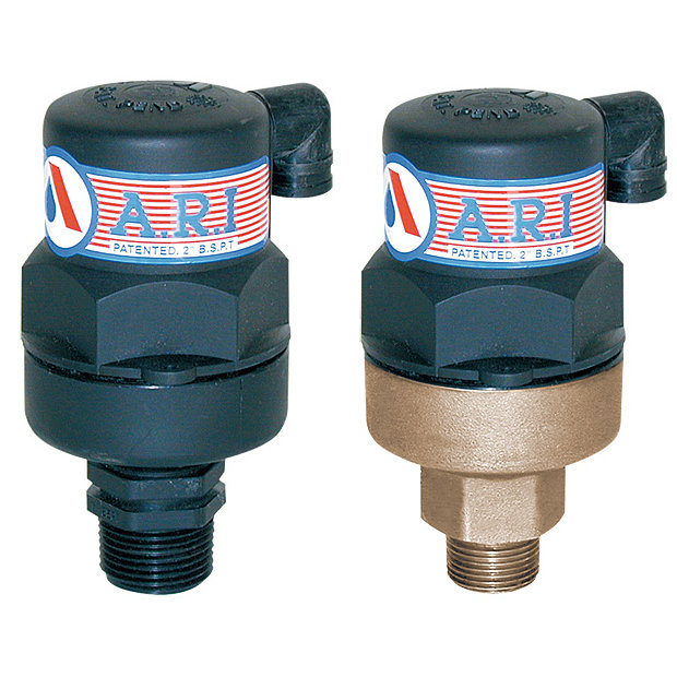
preventers from A.R.I. are comprised of two independent, spring-loaded check valves and a hydraulically operated differential pressure relief valve. These backflow preventers from ARI include Lead Free Bronze shutoff valves at each end of the assembly and are equipped with built-in test cocks.
between your drinking water and high health hazards. Its differential pressure relief valve, allows it to instantly disperse potentially hazardous contaminants from the pipeline.
For more information on sizing, pricing and installation, complete the quick contact form on the contact page and one of our representatives will be happy to answer any questions you have about our 1" inch backflow preventer from ARI. If you have read enough and are ready to move forward with the backflow of tomorrow, simply click “buy now” below and be connected to our secure payment portal. Contractors will benefit from significant discounts when ordering in bulk. For special orders over 50 units, please complete the contact form for pricing, specifying your volume and delivery needs.

Safety valves or pressure relief valves are pressure regulating devices that are responsible for expelling excess pressure from the system when the maximum pressure levels for which they have been designed are exceeded, usually due to a
Safety valves perform their function when the pressure of the system where the fluid is contained, becomes higher than the maximum set pressure of the valve previously adjusted. When the system pressure is higher than the valve’s set
pressure, this opens, releasing the excess pressure to the atmosphere or to containment tanks, depending on the toxicity of the fluid. After releasing the excess, the valve closes again and the system pressure returns to normal.
To ensure total safety of personnel and installation, make sure that the valves have passed all safety tests and meet the requirements of the system where they are to be installed. All our valves are supplied with certificates of materials, cas-
What is the difference between the instantaneous full opening safety valve AIT (PSV) and the normal opening relief valve AN or progressive opening relief valve AP (PRV)?
The Pressure Safety Valve (PSV) opens instantaneously and fully upon reaching the set pressure for which it is designed, expelling the excess pressure from the system immediately. They are optimised for use with steam or gases.
In contrast, the normally or progressively opening Pressure Relief Valve (PRV) opens gradually as the system pressure rises above the set pressure of the valve above its setting. They are optimised to work with liquids.
At VYC Industrial we are specialists in the design and manufacture of all types of safety valves. We have a wide range of safety valves to cover all the needs of the sector.
The Mod. 496 EN safety valve works as an automatic pressure releasing regulator activated by the static pressure existing at the entrance to the valve and is characterized by its ability to open instantly and totally.
The Mod. 495 EN pressure relief valve works as an automatic pressure releasing regulator activated by the static pressure existing at the entrance to the valve and is characterized by its ability to open instantly and totally.
The relief valve works as an automatic pressure releasing regulator activated by the static pressure existing at the entrance to the valve and is characterized by its ability to open instantly and totally.
The valve works as an automatic pressure releasing regulator activated by the static pressure existing at the entrance to the valve and is characterized by its ability to open instantly and totally.
The valve works as an automatic pressure releasing regulator activated by the static pressure existing at the entrance to the valve and is characterized by its ability to open instantly and totally.
The valve works as an automatic pressure releasing regulator activated by the static pressure existing at the entrance to the valve and is characterized by its ability to open instantly and totally.
The valve works as an automatic pressure releasing regulator activated by the static pressure existing at the entrance to the valve and is characterized by its ability to open instantly and totally.
The valve works as an automatic pressure releasing regulator activated by the static pressure existing at the entrance to the valve and is characterized by its ability to open instantly and totally.
The valve works as an automatic pressure releasing regulator activated by the static pressure existing at the entrance to the valve and is characterized by its ability to open, at the fi rst proportional to the pressure increase, and after instantly and totally.
The valve works as an automatic pressure releasing regulator activated by the static pressure existing at the entrance to the valve and is characterized by its ability to open, at the fi rst proportional to the pressure increase, and after instantly and totally.
The valve works as an automatic pressure releasing regulator activated by the static pressure existing at the entrance to the valve and is characterized by its ability to open, at the fi rst proportional to the pressure increase, and after instantly and totally.
The valve works as an automatic pressure releasing regulator activated by the static pressure existing at the entrance to the valve and is characterized by its ability to open proportional to the pressure increase.
The valve works as an automatic pressure releasing regulator activated by the static pressure existing at the entrance to the valve and is characterized by its ability to open proportional to the pressure increase.
The valve works as an automatic pressure releasing regulator activated by the static pressure existing at the entrance to the valve and is characterized by its ability to open instantly and totally.
The valve works as an automatic pressure releasing regulator activated by the static pressure existing at the entrance to the valve and is characterized by its ability to open instantly and totally.
The valve works as an automatic pressure releasing regulator activated by the static pressure existing at the entrance to the valve and is characterized by its ability to open instantly and totally.
The valve works as an automatic pressure releasing regulator activated by the static pressure existing at the entrance to the valve and is characterized by its ability to open instantly and totally.
The valve works as an automatic pressure releasing regulator activated by the static pressure existing at the entrance to the valve and is characterized by its ability to open instantly and totally.
They are used in places such as power, chemical and petrochemical plants to discharge safety valves, control valves, etc. in pressure lines and equipment that convey compressible substances such as steam, air, carbon dioxide, helium, methane, nitrogen, oxygen and other gases.
Test bench for regular inspections and setting and resetting safety valves. Ideal for distributors, maintenance companies or with in-house maintenance. It allows safety valves to be adjusted, tested and/or checked to the test pressure (setting) Pe wile cold (simulating service conditions), matching the opening pressure Ps and the closing pressure Pc, in accordance with the standard regulations.
Controlled safety pressure relief system CSPRS valves are mainly used where conventional direct-loaded spring action valves cannot guarantee the opening and closing margins that certain specifi c conditions of service demand.
The objective is to help the closure by means of pressure so that the valve remains completely watertight until reaching the set pressure and/or to activate the opening with pressure.
Increase the operating pressure of the system up to 99.9% of the set pressure.The control safety pressure relief system CSPRS device can be used with any safety valve available in the market and in particular, with models VYC Mod. 485, 486, 494, 495 and 496.

A safety valve must always be sized and able to vent any source of steam so that the pressure within the protected apparatus cannot exceed the maximum allowable accumulated pressure (MAAP). This not only means that the valve has to be positioned correctly, but that it is also correctly set. The safety valve must then also be sized correctly, enabling it to pass the required amount of steam at the required pressure under all possible fault conditions.
Once the type of safety valve has been established, along with its set pressure and its position in the system, it is necessary to calculate the required discharge capacity of the valve. Once this is known, the required orifice area and nominal size can be determined using the manufacturer’s specifications.
In order to establish the maximum capacity required, the potential flow through all the relevant branches, upstream of the valve, need to be considered.
In applications where there is more than one possible flow path, the sizing of the safety valve becomes more complicated, as there may be a number of alternative methods of determining its size. Where more than one potential flow path exists, the following alternatives should be considered:
This choice is determined by the risk of two or more devices failing simultaneously. If there is the slightest chance that this may occur, the valve must be sized to allow the combined flows of the failed devices to be discharged. However, where the risk is negligible, cost advantages may dictate that the valve should only be sized on the highest fault flow. The choice of method ultimately lies with the company responsible for insuring the plant.
For example, consider the pressure vessel and automatic pump-trap (APT) system as shown in Figure 9.4.1. The unlikely situation is that both the APT and pressure reducing valve (PRV ‘A’) could fail simultaneously. The discharge capacity of safety valve ‘A’ would either be the fault load of the largest PRV, or alternatively, the combined fault load of both the APT and PRV ‘A’.
This document recommends that where multiple flow paths exist, any relevant safety valve should, at all times, be sized on the possibility that relevant upstream pressure control valves may fail simultaneously.
The supply pressure of this system (Figure 9.4.2) is limited by an upstream safety valve with a set pressure of 11.6 bar g. The fault flow through the PRV can be determined using the steam mass flow equation (Equation 3.21.2):
Once the fault load has been determined, it is usually sufficient to size the safety valve using the manufacturer’s capacity charts. A typical example of a capacity chart is shown in Figure 9.4.3. By knowing the required set pressure and discharge capacity, it is possible to select a suitable nominal size. In this example, the set pressure is 4 bar g and the fault flow is 953 kg/h. A DN32/50 safety valve is required with a capacity of 1 284 kg/h.
Coefficients of discharge are specific to any particular safety valve range and will be approved by the manufacturer. If the valve is independently approved, it is given a ‘certified coefficient of discharge’.
This figure is often derated by further multiplying it by a safety factor 0.9, to give a derated coefficient of discharge. Derated coefficient of discharge is termed Kdr= Kd x 0.9
Critical and sub-critical flow - the flow of gas or vapour through an orifice, such as the flow area of a safety valve, increases as the downstream pressure is decreased. This holds true until the critical pressure is reached, and critical flow is achieved. At this point, any further decrease in the downstream pressure will not result in any further increase in flow.
A relationship (called the critical pressure ratio) exists between the critical pressure and the actual relieving pressure, and, for gases flowing through safety valves, is shown by Equation 9.4.2.
Overpressure - Before sizing, the design overpressure of the valve must be established. It is not permitted to calculate the capacity of the valve at a lower overpressure than that at which the coefficient of discharge was established. It is however, permitted to use a higher overpressure (see Table 9.2.1, Module 9.2, for typical overpressure values). For DIN type full lift (Vollhub) valves, the design lift must be achieved at 5% overpressure, but for sizing purposes, an overpressure value of 10% may be used.
For liquid applications, the overpressure is 10% according to AD-Merkblatt A2, DIN 3320, TRD 421 and ASME, but for non-certified ASME valves, it is quite common for a figure of 25% to be used.
Two-phase flow - When sizing safety valves for boiling liquids (e.g. hot water) consideration must be given to vaporisation (flashing) during discharge. It is assumed that the medium is in liquid state when the safety valve is closed and that, when the safety valve opens, part of the liquid vaporises due to the drop in pressure through the safety valve. The resulting flow is referred to as two-phase flow.
The required flow area has to be calculated for the liquid and vapour components of the discharged fluid. The sum of these two areas is then used to select the appropriate orifice size from the chosen valve range. (see Example 9.4.3)
Curtiss-Wright"s selection of Pressure Relief Valves comes from its outstanding product brands Farris and Target Rock. We endeavor to support the whole life cycle of a facility and continuously provide custom products and technologies. Boasting a reputation for producing high quality, durable products, our collection of Pressure Relief Valves is guaranteed to provide effective and reliable pressure relief.
While some basic components and activations in relieving pressure may differ between the specific types of relief valves, each aims to be 100% effective in keeping your equipment running safely. Our current range includes numerous valve types, from flanged to spring-loaded, threaded to wireless, pilot operated, and much more.
A pressure relief valve is a type of safety valve designed to control the pressure in a vessel. It protects the system and keeps the people operating the device safely in an overpressure event or equipment failure.
A pressure relief valve is designed to withstand a maximum allowable working pressure (MAWP). Once an overpressure event occurs in the system, the pressure relief valve detects pressure beyond its design"s specified capability. The pressure relief valve would then discharge the pressurized fluid or gas to flow from an auxiliary passage out of the system.
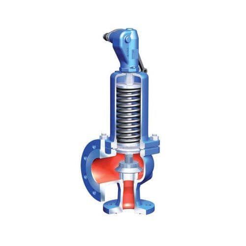
Below is an example of one of our pilot operated pressure relief valves in action; the cutaway demonstrates when high pressure is released from the system.
Air pressure relief valves can be applied to a variety of environments and equipment. Pressure relief valves are a safety valve used to keep equipment and the operators safe too. They"re instrumental in applications where proper pressure levels are vital for correct and safe operation. Such as oil and gas, power generation like central heating systems, and multi-phase applications in refining and chemical processing.
At Curtiss-Wright, we provide a range of different pressure relief valves based on two primary operations – spring-loaded and pilot operated. Spring-loaded valves can either be conventional spring-loaded or balanced spring-loaded.
Spring-loaded valves are programmed to open and close via a spring mechanism. They open when the pressure reaches an unacceptable level to release the material inside the vessel. It closes automatically when the pressure is released, and it returns to an average operating level. Spring-loaded safety valves rely on the closing force applied by a spring onto the main seating area. They can also be controlled in numerous ways, such as a remote, control panel, and computer program.
Pilot-operated relief valves operate by combining the primary relieving device (main valve) with self-actuated auxiliary pressure relief valves, also known as the pilot control. This pilot control dictates the opening and closing of the main valve and responds to system pressure. System pressure is fed from the inlet into and through the pilot control and ultimately into the main valve"s dome. In normal operating conditions, system pressure will prevent the main valve from opening.
The valves allow media to flow from an auxiliary passage and out of the system once absolute pressure is reached, whether it is a maximum or minimum level.
When the pressure is below the maximum amount, the pressure differential is slightly positive on the piston"s dome size, which keeps the main valve in the closed position. When system pressure rises and reaches the set point, the pilot will cut off flow to the dome, causing depressurization in the piston"s dome side. The pressure differential has reversed, and the piston will rise, opening the main valve, relieving pressure.
When the process pressure decreases to a specific pressure, the pilot closes, the dome is repressurized, and the main valve closes. The main difference between spring-loaded PRVs and pilot-operated is that a pilot-operated safety valve uses pressure to keep the valve closed.
Pilot-operated relief valves are controlled by hand and are typically opened often through a wheel or similar component. The user opens the valve when the gauge signifies that the system pressure is at an unsafe level; once the valve has opened and the pressure has been released, the operator can shut it by hand again.
Increasing pressure helps to maintain the pilot"s seal. Once the setpoint has been reached, the valve opens. This reduces leakage and fugitive emissions.
At set pressure the valve snaps to full lift. This can be quite violent on large pipes with significant pressure. The pressure has to drop below the set pressure in order for the piston to reseat.
At Curtiss-Wright we also provide solutions for pressure relief valve monitoring. Historically, pressure relief valves have been difficult or impossible to monitor. Our SmartPRV features a 2600 Series pressure relief valve accessorized with a wireless position monitor that alerts plant operators during an overpressure event, including the time and duration.
There are many causes of overpressure, but the most common ones are typically blocked discharge in the system, gas blowby, and fire. Even proper inspection and maintenance will not eliminate the occurrence of leakages. An air pressure relief valve is the only way to ensure a safe environment for the device, its surroundings, and operators.
A PRV and PSV are interchangeable, but there is a difference between the two valves. A pressure release valve gradually opens when experiencing pressure, whereas a pressure safety valve opens suddenly when the pressure hits a certain level of over pressurization. Safety valves can be used manually and are typically used for a permanent shutdown. Air pressure relief valves are used for operational requirements, and they gently release the pressure before it hits the maximum high-pressure point and circulates it back into the system.
Pressure relief valves should be subject to an annual test, one per year. The operator is responsible for carrying out the test, which should be done using an air compressor. It’s imperative to ensure pressure relief valves maintain their effectiveness over time and are checked for signs of corrosion and loss of functionality. Air pressure relief valves should also be checked before their installation, after each fire event, and regularly as decided by the operators.
Direct-acting solenoid valves have a direct connection with the opening and closing armature, whereas pilot-operated valves use of the process fluid to assist in piloting the operation of the valve.
A control valve works by varying the rate of fluid passing through the valve itself. As the valve stem moves, it alters the size of the passage and increases, decreases or holds steady the flow. The opening and closing of the valve is altered whenever the controlled process parameter does not reach the set point.
Control valves are usually at floor level or easily accessible via platforms. They are also located on the same equipment or pipeline as the measurement and downstream or flow measurements.
An industrial relief valve is designed to control or limit surges of pressure in a system, most often in fluid or compressed air system valves. It does so as a form of protection for the system and defending against instrument or equipment failure. They are usually present in clean water industries.
A PRV is often referred to as a pressure relief valve, which is also known as a PSV or pressure safety valve. They are used interchangeably throughout the industry depending on company standards.


 8613371530291