
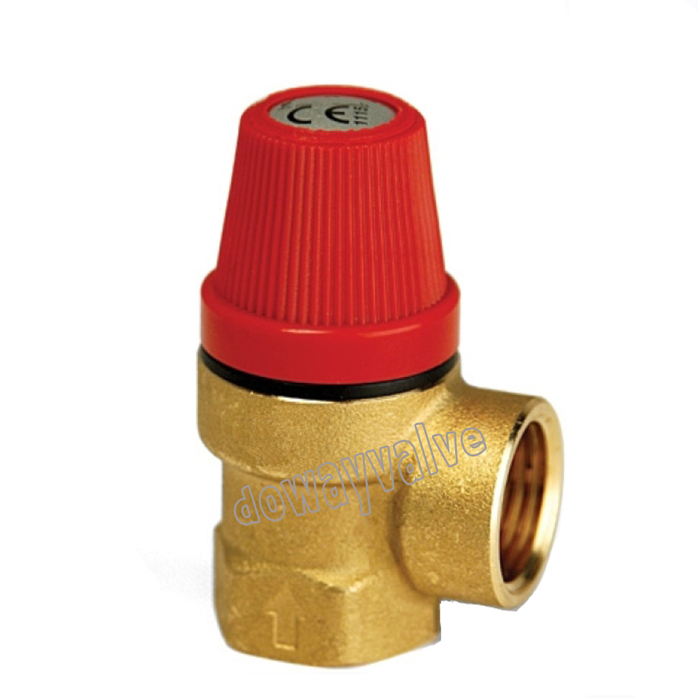
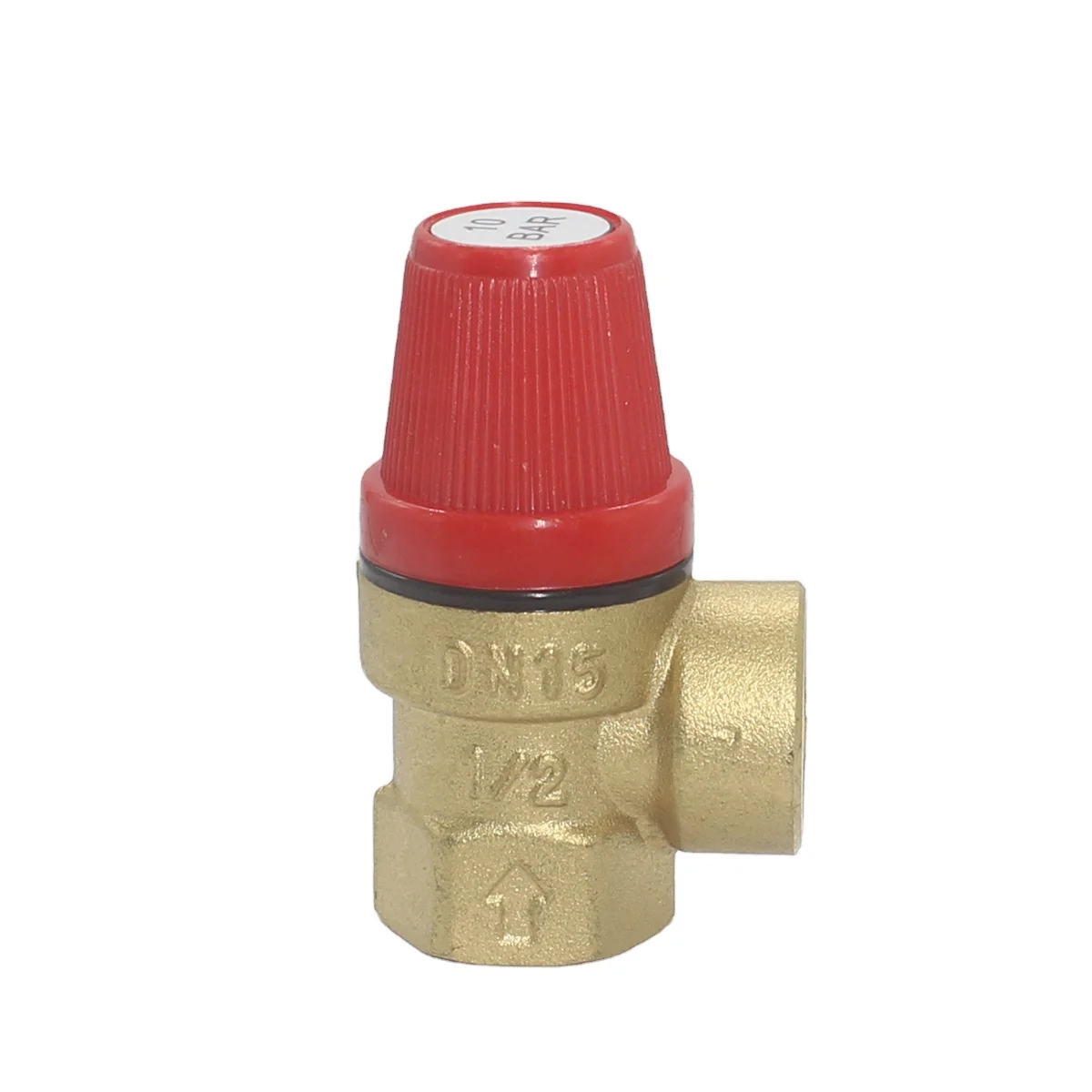
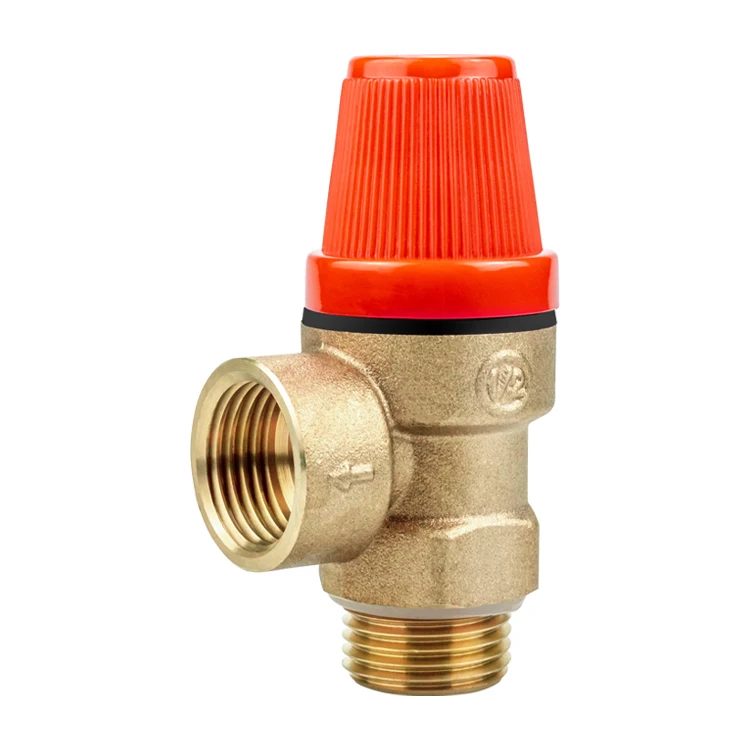
3 bar safety valve manufacturer
... -start valve with Series MX2 air treatment units without the need for additional connection interfaces. The soft-start valve is positioned upstream of the safety valves, ...
Two hands safety valve, which allows a safety use of two hands pneumatic controls (for example two push-button 3/2 N.C. to a certain distance) excluding false signals in case of push-button ...
The SI2 safety valve prevents the allowed operating pressure from being exceeded by more than 10%. If, after opening, the adjusted response pressure falls ...
... stainless steel full-lift clean service safety valve designed to AD Merkblatt A2 and TRD 421 standards and suitable for pure steam, vapour and inert gases.
Insert style flow control valves are comprised of a precision orifice in parallel with a check valve, combined into a single component. Each is designed for easy installation into metal housings using ...
Press-in style flow control valves are comprised of a precision flow orifice in parallel with a check valve, combined into a single component. Each part is designed for easy installation into plastic ...
If you have been searching for a safety release valve that you can use to reduce short-term pressure surges successfully and diminish the effects of gas leaks, this is the product for you. With a pe of ...
... have been type tested as well. These pressure regulators have safety valves which will slam shut in the event of emergencies, such as the gas reaching too high a pressure level. The valve ...
This product has hydraulically actuated class A gas safety valves to EN 161 used for automatic shut-off. It shuts off when unstimulated for gas and air, or even biologically produced methane. It has AISi ...
The S 104 Safety Shut Off valve is mainly used to avoid any damage to components as well as to avoid too high or too low pressure in the gas train. This could cause high financial losses and/or injured ...
The S50 Safety Shut Off valve is mainly used to avoid any damage to components as well as to avoid too high or too low pressure in the gas train. This could cause high financial losses and/or injured ...
The S100 Safety Shut Off valve is mainly used to avoid any damage to components as well as to avoid too high or too low pressure in the gas train. This could cause high financial losses and/or injured ...
... Pressure Safety Valve + Rupture Disk is protected and may be utilized autonomously as essential security gadgets or in conjunction. There are 3 possible combinations. The first combinations ...
Excavator pipe-rupture valves prevent uncontrolled cylinder movement in the event that a pipe or hose bursts. The ESV valve fulfills all of the requirements of the ISO 8643 and EN 474-5 standards for ...
Material: Body- CF8M; Valve Seat- CF8M Métal Seat, PTFE Soft Seat available Orifice Size: fc"(15mm), 3/4M(20mm), l"(25mm), l1/4,’(32mm)I ltë”(40mm), ...
The Safety valves from ATOS are designed to guarantee protection for application on various devices, especially those that monitor spool position. They are also recommended for hydraulic ...
... -start valve with Series MX2 air treatment units without the need for additional connection interfaces. The soft-start valve is positioned upstream of the safety valves, ...
The S50 Safety Shut Off valve is mainly used to avoid any damage to components as well as to avoid too high or too low pressure in the gas train. This could cause high financial losses and/or injured ...
The S100 Safety Shut Off valve is mainly used to avoid any damage to components as well as to avoid too high or too low pressure in the gas train. This could cause high financial losses and/or injured ...
2½” MEGA SUPERVENTIX™ threaded safety relief valve is designed to protect tanks against accidental overpressure and excessive vacuum. With a smart compact design, the 2½” BSP MEGA SUPERVENTIX™ ...
... Breather Valve requires no field maintenance. Corrosion-resistant materials are used throughout. The valve seal is made of silicone rubber. Each valve comes complete with a nut and o-ring, ...

The primary purpose of a safety valve is to protect life, property and the environment. Safety valves are designed to open and release excess pressure from vessels or equipment and then close again.
The function of safety valves differs depending on the load or main type of the valve. The main types of safety valves are spring-loaded, weight-loaded and controlled safety valves.
Regardless of the type or load, safety valves are set to a specific set pressure at which the medium is discharged in a controlled manner, thus preventing overpressure of the equipment. In dependence of several parameters such as the contained medium, the set pressure is individual for each safety application.

In addition to the small installation space of the above-mentioned compressors, they should be completely covered by an acoustic enclosure to reduce noise emissions. In order to reduce the size of the very cost-intensive sound enclosure, AERZEN requires special valves that are adapted to the available small installation space. Compressors are discontinuous machines for pressure generation.
In order to ensure that occurring pulsations do not impair the function of the safety valve, the set pressure of the valve is adjusted accordingly and an appropriate distance to the pressure line is ensured by design.
The LESER solutionAs a renowned manufacturer of safety valves, it is advantageous to be able to react flexibly to the above-mentioned concerns, primarily to the small installation space, with its portfolio. Being able to change the installation position of safety valves is a clear advantage for the compressor designer. They are much more variable in their design and construction options and can also respond more flexibly to special customer specifications. If the progressive modularization of compressors requires more compact designs, safety valves in different mounting positions, for example, can be an answer to the problem, unlike the classic upright position. In addition, the spindle guide plays a special role here. The friction at the guiding points must be reduced as much as possible so that the spindle runs smoothly. Otherwise, a safety valve can only be installed vertically.
Why LESER safety valves?For a global acting OEM like AERZEN, a specialist like LESER, who has not only the knowledge but also the necessary approvals, is an important component for success. LESER offers a global approval concept that allows safety valves to be used regardless of location. When ordering safety valves, only the applicable regulations must be specified in order to ensure appropriate labeling and material selection. In addition, LESER has tested and approved further installation positions in addition to the conventional installation situation, standing on the inlet pipeline. For example, some types of valves may be installed with a horizontal stem or even upside down, e.g. Types 526 and 441. For horizontal installation, care must be taken to align the outlet. Liquids, e.g. in the form of condensate, should be able to drain off downwards to avoid back pressures and even corrosion. When installed upside down, the inverted weight forces are corrected by correction factors. LESER offers not only safety valves with basic documentation and accessories but also other special documentation and options. From the “Fugitive Emission Test” with helium up to 3.2 ship class castings and from back pressures up to more than 200 bar-g to high pressure heating jackets for up to 30 bar-g, LESER sales engineers develop solutions for customer specific applications as described above for AERZEN.
They can also be used in a variety of ways, such as using a vacuum to cleanose oil or by aressedressed engine. These pressure relief valves perform very high pressure and have a low-pressure ratio as they are made by compressed oil into a solid.
Pressure relief valves are equipped with a hydraulic compressor and airflow, which allows the air to throughressressed material. They eliminate the need for build-time and a proper pressure relief valve is by applying pressure on the valves" top, they prevent air from build-up.
Business buyers can buy and sell, they have the information to choose them. The Ption allows for good pressure reducing valve and low pressure valve, but pressure reducing valve prices are not based on their needs.
{"parentMemberDN":"dc=parker,dc=corp","organizationDistinguishedName":"dc=parker,dc=corp","resourceId":"https:\/\/cor089w46.us.parker.corp\/wcs\/resources\/lbs\/store\/23551\/person\/@self","contactUrl":"https:\/\/cor089w46.us.parker.corp\/wcs\/resources\/lbs\/store\/23551\/person\/@self\/contact","orgizationId":"-2000","userId":"-1002","checkoutProfileUrl":"https:\/\/cor089w46.us.parker.corp\/wcs\/resources\/lbs\/store\/23551\/person\/@self\/checkoutProfile","resourceName":"person"}

Ningbo Doway M&E Co., Ltd. is built in Ningbo China, which is established in 2000. We specialized in manufacturing brass & bronze valves and fittings, water meter accessories and pipe fittings. Our mainly products cover ball valves, angle valves, gate valves, check valves, bib cocks, marine valves, pipe fittings, PPR insert, radiator valves and fittings, camlock and grooved couplings etc.
Nowadays, we are involving in the fields of brass forged, brass investment casting, bronze sand casting, brass/bronze gravity casting etc. Our products are widely used in water and plumbing systems and well recognized in Europe, USA, Middle East and Other Land with competitive price, quality products, and considerate service. Our company passed ISO9001 Certification and CE Approval for our ball valves, and UL approval for our bronze ball valves.
Based on the Spirit "Honesty, Pragmatic, Innovation", we are proud to own one professional team and provided customers competitive prices, quality products with On Time Delivery. Also we have strong OEM and ODM ability for clients to supply various valves and fittings in brass & bronze material for water solution.
Industry leading pressure and safety relief valve designs with over 140 years of technical and application expertise providing custom engineered solutions for O&G, Refining, Chemical, Petrochemical, Process and Power applications. Our designs meet global and local codes and standards (API 526; ASME Section I, IV & VIII; EN ISO 4126; PED & more). Gain insight into the performance of your pressure relief valves with wireless monitoring.

There is a wide range of safety valves available to meet the many different applications and performance criteria demanded by different industries. Furthermore, national standards define many varying types of safety valve.
The ASME standard I and ASME standard VIII for boiler and pressure vessel applications and the ASME/ANSI PTC 25.3 standard for safety valves and relief valves provide the following definition. These standards set performance characteristics as well as defining the different types of safety valves that are used:
ASME I valve - A safety relief valve conforming to the requirements of Section I of the ASME pressure vessel code for boiler applications which will open within 3% overpressure and close within 4%. It will usually feature two blowdown rings, and is identified by a National Board ‘V’ stamp.
ASME VIII valve- A safety relief valve conforming to the requirements of Section VIII of the ASME pressure vessel code for pressure vessel applications which will open within 10% overpressure and close within 7%. Identified by a National Board ‘UV’ stamp.
Full bore safety valve - A safety valve having no protrusions in the bore, and wherein the valve lifts to an extent sufficient for the minimum area at any section, at or below the seat, to become the controlling orifice.
Conventional safety relief valve -The spring housing is vented to the discharge side, hence operational characteristics are directly affected by changes in the backpressure to the valve.
Balanced safety relief valve -A balanced valve incorporates a means of minimising the effect of backpressure on the operational characteristics of the valve.
Pilot operated pressure relief valve -The major relieving device is combined with, and is controlled by, a self-actuated auxiliary pressure relief device.
Power-actuated safety relief valve - A pressure relief valve in which the major pressure relieving device is combined with, and controlled by, a device requiring an external source of energy.
Standard safety valve - A valve which, following opening, reaches the degree of lift necessary for the mass flowrate to be discharged within a pressure rise of not more than 10%. (The valve is characterised by a pop type action and is sometimes known as high lift).
Full lift (Vollhub) safety valve -A safety valve which, after commencement of lift, opens rapidly within a 5% pressure rise up to the full lift as limited by the design. The amount of lift up to the rapid opening (proportional range) shall not be more than 20%.
Direct loaded safety valve -A safety valve in which the opening force underneath the valve disc is opposed by a closing force such as a spring or a weight.
Proportional safety valve - A safety valve which opens more or less steadily in relation to the increase in pressure. Sudden opening within a 10% lift range will not occur without pressure increase. Following opening within a pressure of not more than 10%, these safety valves achieve the lift necessary for the mass flow to be discharged.
Diaphragm safety valve -A direct loaded safety valve wherein linear moving and rotating elements and springs are protected against the effects of the fluid by a diaphragm
Bellows safety valve - A direct loaded safety valve wherein sliding and (partially or fully) rotating elements and springs are protected against the effects of the fluids by a bellows. The bellows may be of such a design that it compensates for influences of backpressure.
Controlled safety valve - Consists of a main valve and a control device. It also includes direct acting safety valves with supplementary loading in which, until the set pressure is reached, an additional force increases the closing force.
Safety valve - A safety valve which automatically, without the assistance of any energy other than that of the fluid concerned, discharges a quantity of the fluid so as to prevent a predetermined safe pressure being exceeded, and which is designed to re-close and prevent further flow of fluid after normal pressure conditions of service have been restored. Note; the valve can be characterised either by pop action (rapid opening) or by opening in proportion (not necessarily linear) to the increase in pressure over the set pressure.
Direct loaded safety valve -A safety valve in which the loading due to the fluid pressure underneath the valve disc is opposed only by a direct mechanical loading device such as a weight, lever and weight, or a spring.
Assisted safety valve -A safety valve which by means of a powered assistance mechanism, may additionally be lifted at a pressure lower than the set pressure and will, even in the event of a failure of the assistance mechanism, comply with all the requirements for safety valves given in the standard.
Supplementary loaded safety valve - A safety valve that has, until the pressure at the inlet to the safety valve reaches the set pressure, an additional force, which increases the sealing force.
Note; this additional force (supplementary load), which may be provided by means of an extraneous power source, is reliably released when the pressure at the inlet of the safety valve reaches the set pressure. The amount of supplementary loading is so arranged that if such supplementary loading is not released, the safety valve will attain its certified discharge capacity at a pressure not greater than 1.1 times the maximum allowable pressure of the equipment to be protected.
Pilot operated safety valve -A safety valve, the operation of which is initiated and controlled by the fluid discharged from a pilot valve, which is itself, a direct loaded safety valve subject to the requirement of the standard.
The common characteristic shared between the definitions of conventional safety valves in the different standards, is that their operational characteristics are affected by any backpressure in the discharge system. It is important to note that the total backpressure is generated from two components; superimposed backpressure and the built-up backpressure:
Subsequently, in a conventional safety valve, only the superimposed backpressure will affect the opening characteristic and set value, but the combined backpressure will alter the blowdown characteristic and re-seat value.
The ASME/ANSI standard makes the further classification that conventional valves have a spring housing that is vented to the discharge side of the valve. If the spring housing is vented to the atmosphere, any superimposed backpressure will still affect the operational characteristics. Thiscan be seen from Figure 9.2.1, which shows schematic diagrams of valves whose spring housings are vented to the discharge side of the valve and to the atmosphere.
By considering the forces acting on the disc (with area AD), it can be seen that the required opening force (equivalent to the product of inlet pressure (PV) and the nozzle area (AN)) is the sum of the spring force (FS) and the force due to the backpressure (PB) acting on the top and bottom of the disc. In the case of a spring housing vented to the discharge side of the valve (an ASME conventional safety relief valve, see Figure 9.2.1 (a)), the required opening force is:
In both cases, if a significant superimposed backpressure exists, its effects on the set pressure need to be considered when designing a safety valve system.
Once the valve starts to open, the effects of built-up backpressure also have to be taken into account. For a conventional safety valve with the spring housing vented to the discharge side of the valve, see Figure 9.2.1 (a), the effect of built-up backpressure can be determined by considering Equation 9.2.1 and by noting that once the valve starts to open, the inlet pressure is the sum of the set pressure, PS, and the overpressure, PO.
Balanced safety valves are those that incorporate a means of eliminating the effects of backpressure. There are two basic designs that can be used to achieve this:
Although there are several variations of the piston valve, they generally consist of a piston type disc whose movement is constrained by a vented guide. The area of the top face of the piston, AP, and the nozzle seat area, AN, are designed to be equal. This means that the effective area of both the top and bottom surfaces of the disc exposed to the backpressure are equal, and therefore any additional forces are balanced. In addition, the spring bonnet is vented such that the top face of the piston is subjected to atmospheric pressure, as shown in Figure 9.2.2.
The bellows arrangement prevents backpressure acting on the upper side of the disc within the area of the bellows. The disc area extending beyond the bellows and the opposing disc area are equal, and so the forces acting on the disc are balanced, and the backpressure has little effect on the valve opening pressure.
Bellows failure is an important concern when using a bellows balanced safety valve, as this may affect the set pressure and capacity of the valve. It is important, therefore, that there is some mechanism for detecting any uncharacteristic fluid flow through the bellows vents. In addition, some bellows balanced safety valves include an auxiliary piston that is used to overcome the effects of backpressure in the case of bellows failure. This type of safety valve is usually only used on critical applications in the oil and petrochemical industries.
Since balanced pressure relief valves are typically more expensive than their unbalanced counterparts, they are commonly only used where high pressure manifolds are unavoidable, or in critical applications where a very precise set pressure or blowdown is required.
This type of safety valve uses the flowing medium itself, through a pilot valve, to apply the closing force on the safety valve disc. The pilot valve is itself a small safety valve.
The diaphragm type is typically only available for low pressure applications and it produces a proportional type action, characteristic of relief valves used in liquid systems. They are therefore of little use in steam systems, consequently, they will not be considered in this text.
The piston type valve consists of a main valve, which uses a piston shaped closing device (or obturator), and an external pilot valve. Figure 9.2.4 shows a diagram of a typical piston type, pilot operated safety valve.
The piston and seating arrangement incorporated in the main valve is designed so that the bottom area of the piston, exposed to the inlet fluid, is less than the area of the top of the piston. As both ends of the piston are exposed to the fluid at the same pressure, this means that under normal system operating conditions, the closing force, resulting from the larger top area, is greater than the inlet force. The resultant downward force therefore holds the piston firmly on its seat.
If the inlet pressure were to rise, the net closing force on the piston also increases, ensuring that a tight shut-off is continually maintained. However, when the inlet pressure reaches the set pressure, the pilot valve will pop open to release the fluid pressure above the piston. With much less fluid pressure acting on the upper surface of the piston, the inlet pressure generates a net upwards force and the piston will leave its seat. This causes the main valve to pop open, allowing the process fluid to be discharged.
When the inlet pressure has been sufficiently reduced, the pilot valve will reclose, preventing the further release of fluid from the top of the piston, thereby re-establishing the net downward force, and causing the piston to reseat.
Pilot operated safety valves offer good overpressure and blowdown performance (a blowdown of 2% is attainable). For this reason, they are used where a narrow margin is required between the set pressure and the system operating pressure. Pilot operated valves are also available in much larger sizes, making them the preferred type of safety valve for larger capacities.
One of the main concerns with pilot operated safety valves is that the small bore, pilot connecting pipes are susceptible to blockage by foreign matter, or due to the collection of condensate in these pipes. This can lead to the failure of the valve, either in the open or closed position, depending on where the blockage occurs.
The terms full lift, high lift and low lift refer to the amount of travel the disc undergoes as it moves from its closed position to the position required to produce the certified discharge capacity, and how this affects the discharge capacity of the valve.
A full lift safety valve is one in which the disc lifts sufficiently, so that the curtain area no longer influences the discharge area. The discharge area, and therefore the capacity of the valve are subsequently determined by the bore area. This occurs when the disc lifts a distance of at least a quarter of the bore diameter. A full lift conventional safety valve is often the best choice for general steam applications.
The disc of a high lift safety valve lifts a distance of at least 1/12th of the bore diameter. This means that the curtain area, and ultimately the position of the disc, determines the discharge area. The discharge capacities of high lift valves tend to be significantly lower than those of full lift valves, and for a given discharge capacity, it is usually possible to select a full lift valve that has a nominal size several times smaller than a corresponding high lift valve, which usually incurs cost advantages.Furthermore, high lift valves tend to be used on compressible fluids where their action is more proportional.
In low lift valves, the disc only lifts a distance of 1/24th of the bore diameter. The discharge area is determined entirely by the position of the disc, and since the disc only lifts a small amount, the capacities tend to be much lower than those of full or high lift valves.
Except when safety valves are discharging, the only parts that are wetted by the process fluid are the inlet tract (nozzle) and the disc. Since safety valves operate infrequently under normal conditions, all other components can be manufactured from standard materials for most applications. There are however several exceptions, in which case, special materials have to be used, these include:
Cast steel -Commonly used on higher pressure valves (up to 40 bar g). Process type valves are usually made from a cast steel body with an austenitic full nozzle type construction.
For all safety valves, it is important that moving parts, particularly the spindle and guides are made from materials that will not easily degrade or corrode. As seats and discs are constantly in contact with the process fluid, they must be able to resist the effects of erosion and corrosion.
The spring is a critical element of the safety valve and must provide reliable performance within the required parameters. Standard safety valves will typically use carbon steel for moderate temperatures. Tungsten steel is used for higher temperature, non-corrosive applications, and stainless steel is used for corrosive or clean steam duty. For sour gas and high temperature applications, often special materials such as monel, hastelloy and ‘inconel’ are used.
Standard safety valves are generally fitted with an easing lever, which enables the valve to be lifted manually in order to ensure that it is operational at pressures in excess of 75% of set pressure. This is usually done as part of routine safety checks, or during maintenance to prevent seizing. The fitting of a lever is usually a requirement of national standards and insurance companies for steam and hot water applications. For example, the ASME Boiler and Pressure Vessel Code states that pressure relief valves must be fitted with a lever if they are to be used on air, water over 60°C, and steam.
A test gag (Figure 9.2.7) may be used to prevent the valve from opening at the set pressure during hydraulic testing when commissioning a system. Once tested, the gag screw is removed and replaced with a short blanking plug before the valve is placed in service.
The amount of fluid depends on the particular design of safety valve. If emission of this fluid into the atmosphere is acceptable, the spring housing may be vented to the atmosphere – an open bonnet. This is usually advantageous when the safety valve is used on high temperature fluids or for boiler applications as, otherwise, high temperatures can relax the spring, altering the set pressure of the valve. However, using an open bonnet exposes the valve spring and internals to environmental conditions, which can lead to damage and corrosion of the spring.
When the fluid must be completely contained by the safety valve (and the discharge system), it is necessary to use a closed bonnet, which is not vented to the atmosphere. This type of spring enclosure is almost universally used for small screwed valves and, it is becoming increasingly common on many valve ranges since, particularly on steam, discharge of the fluid could be hazardous to personnel.
Some safety valves, most commonly those used for water applications, incorporate a flexible diaphragm or bellows to isolate the safety valve spring and upper chamber from the process fluid, (see Figure 9.2.9).

The following navigation utilizes arrow, enter, escape, and space bar key commands. Left and right arrows move across top level links and expand / close menus in sub levels. Up and Down arrows will open main level menus and toggle through sub tier links. Enter and space open menus and escape closes them as well. Tab will move on to the next part of the site rather than go through menu items.

Relief valves are designed to open at a preset pressure (or temperature) level and relieve the system when it has exceeded the desired level. The valve"s relief of elevated liquid, gas, or steam pressures prevents damage to the system. We offer a wide selection of relief valves for any application.


 8613371530291