
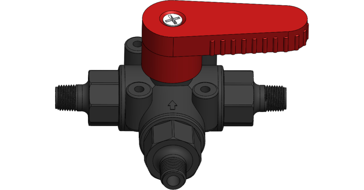
3 way safety valve free sample
A thermostatic mixing valve can be installed to replace your existing mixing valve to provide the perfect balance of hot and cold water. These valves are designed to control your home’s water temperature, allowing you to set it at just the right level if you’re looking for an affordable way to maintain a comfortable environment in your home or office.
Thermostatic mixing valves are perfect for situations where you need to maintain a precise water temperature. For example, if you’re using a washer and dryer in an apartment or home with shared laundry facilities, the faucet’s water mustn’t be too hot or cold. Installing a thermostatic mixing valve can help prevent accidents and keep your clothes from shrinking or fading.
If you’re looking for an affordable way to maintain a comfortable environment in your home or office, look no further than this blog post! Thermostatic mixing valves are perfect for situations where you need to maintain a precise water temperature. For example, if you’re using a washer and dryer in an apartment or home with shared laundry facilities, the faucet’s water mustn’t be too hot or cold. Installing a thermostatic mixing valve can help prevent accidents and keep your clothes from shrinking or fading.
What is a 3-way Actuator and Thermostatic Mixing Valve? This device controls water temperature for industrial, commercial, and residential applications. The 3-way actuator leverages a combination of functions to precisely regulate and mix hot and cold water. It’s an essential component in any plumbing system that needs to deliver hot water at precise temperatures.
A 3-way actuator consists of three valves, two designed to control the flow rate and temperature range of hot or cold supplies, while the third modulates the combined flow. An adjustable thermostat monitors incoming temperatures, allowing the device to adjust output accurately. These valves are also designed with safety features such as overheat cutoffs that stop operation when necessary.
The 3-way actuator is a device that can be used to regulate the temperature of liquids and gases. It is an essential component of a thermostatic mixing valve, which helps maintain the desired comfort level in a room by controlling the flow of hot and cold water. This article explores the benefits that come with using a 3-way actuator.
A thermostatic mixing valve is essential to many commercial and residential plumbing systems. It helps regulate the water temperature to maintain a safe and comfortable environment while protecting against scalding. This article will explore the benefits of installing a thermostatic mixing valve in your plumbing system.
Thermostatic mixing valves are designed to precisely control the water temperature by blending hot and cold water. This allows for a more excellent range of temperatures than regular plumbing fixtures, which can help reduce energy consumption by reducing the energy required to heat or cool the water. They also provide enhanced safety features such as scald protection, which will automatically shut off hot water if it reaches unsafe levels.
A 3-way actuator and thermostatic mixing valve work together to regulate the temperature of hot and cold water in various applications. These components are essential for controlling the water temperature and providing safety and comfort. Understanding how these two components interact is key to ensuring optimal performance in any system.
A 3-way actuator is a component used to control the flow of hot and cold water into a mixing chamber. It consists of three ports, one for hot water, one for cold water, and an outlet that combines both streams into a single output stream. The 3-way actuator works by diverting either more or less hot or cold water into the mixture depending on what is required at any given time.
A 3-way actuator and thermostatic mixing valve offer many applications for commercial and industrial uses. These two components regulate temperatures, allowing precise control over hot and cold supplies. This makes them ideal for cooling towers, chillers, boilers, heat exchangers, and more.
The 3-way actuator is designed to provide accurate flow control through a variety of commercial or industrial systems by controlling the switching between hot and cold water supplies with the appropriate temperature set points. It works with the thermostatic mixing valve, which is responsible for accurately regulating temperatures by combining hot and cold water sources within a system. Together both components allow users to maintain desired temperatures within their plans regardless of fluctuations in supply pressure or flow rate conditions.
This article will explore installing and maintaining a 3-way actuator and thermostatic mixing valve. This type of valve is commonly used in hydronic heating systems, cooling tower water treatment, and medical gas systems. Installation of these valves requires careful consideration of safety protocols, pipe fitting protocols, and system requirements to ensure proper operation. A technician should be consulted to avoid potential hazards when installing or maintaining any actuator or mixing valve.
During maintenance, it is important to keep an eye on the various parts that make up the 3-way actuator and thermostatic mixing valve. Proper lubrication should be applied to all moving parts regularly while checking on wear caused by friction or other environmental factors that can help prevent costly repairs.

Besides the P/T value of the sleeve the limitations of the valve bodies also have to be considered. Please refer to the EN 12516-1 resp. ASME B16.34 in order to choose a proper pressure rating (PN/class). The shown values refer to austenitic stainless steel 1.4408 (A351 Gr. CF8M).

Vacuum controlled 3 Way Valves apply signal pressure to a diaphragm that is opposed by a spring force. When then vacuum signal force is greater (deeper vacuum = more force) than the spring force it reaches its set-point (also called “On” pressure), the internal mechanism moves and changes the pneumatic state.
When the valve trips, the supply is shut off and the output port is vented through the exhaust to atmosphere. There is no connection available on the exhaust port. The valve will remain in this state until the pressure signal drops below its reset point (also called “Off” pressure).
Adjustments can be made to the switch by removing the round cover and turning the flat head screw. Clockwise adjustments will raise the Set point. Counter clockwise adjustments will lower the setpoint (on pressure). Adjusting preset 3-way valves is not recommended. Do not back out the flat head screw above flush with the body.

The primary purpose of a safety valve is to protect life, property and the environment. Safety valves are designed to open and release excess pressure from vessels or equipment and then close again.
The function of safety valves differs depending on the load or main type of the valve. The main types of safety valves are spring-loaded, weight-loaded and controlled safety valves.
Regardless of the type or load, safety valves are set to a specific set pressure at which the medium is discharged in a controlled manner, thus preventing overpressure of the equipment. In dependence of several parameters such as the contained medium, the set pressure is individual for each safety application.
A safety valve must always be sized and able to vent any source of steam so that the pressure within the protected apparatus cannot exceed the maximum allowable accumulated pressure (MAAP). This not only means that the valve has to be positioned correctly, but that it is also correctly set. The safety valve must then also be sized correctly, enabling it to pass the required amount of steam at the required pressure under all possible fault conditions.
Once the type of safety valve has been established, along with its set pressure and its position in the system, it is necessary to calculate the required discharge capacity of the valve. Once this is known, the required orifice area and nominal size can be determined using the manufacturer’s specifications.
In order to establish the maximum capacity required, the potential flow through all the relevant branches, upstream of the valve, need to be considered.
In applications where there is more than one possible flow path, the sizing of the safety valve becomes more complicated, as there may be a number of alternative methods of determining its size. Where more than one potential flow path exists, the following alternatives should be considered:
This choice is determined by the risk of two or more devices failing simultaneously. If there is the slightest chance that this may occur, the valve must be sized to allow the combined flows of the failed devices to be discharged. However, where the risk is negligible, cost advantages may dictate that the valve should only be sized on the highest fault flow. The choice of method ultimately lies with the company responsible for insuring the plant.
For example, consider the pressure vessel and automatic pump-trap (APT) system as shown in Figure 9.4.1. The unlikely situation is that both the APT and pressure reducing valve (PRV ‘A’) could fail simultaneously. The discharge capacity of safety valve ‘A’ would either be the fault load of the largest PRV, or alternatively, the combined fault load of both the APT and PRV ‘A’.
This document recommends that where multiple flow paths exist, any relevant safety valve should, at all times, be sized on the possibility that relevant upstream pressure control valves may fail simultaneously.
The supply pressure of this system (Figure 9.4.2) is limited by an upstream safety valve with a set pressure of 11.6 bar g. The fault flow through the PRV can be determined using the steam mass flow equation (Equation 3.21.2):
Once the fault load has been determined, it is usually sufficient to size the safety valve using the manufacturer’s capacity charts. A typical example of a capacity chart is shown in Figure 9.4.3. By knowing the required set pressure and discharge capacity, it is possible to select a suitable nominal size. In this example, the set pressure is 4 bar g and the fault flow is 953 kg/h. A DN32/50 safety valve is required with a capacity of 1 284 kg/h.
Coefficients of discharge are specific to any particular safety valve range and will be approved by the manufacturer. If the valve is independently approved, it is given a ‘certified coefficient of discharge’.
This figure is often derated by further multiplying it by a safety factor 0.9, to give a derated coefficient of discharge. Derated coefficient of discharge is termed Kdr= Kd x 0.9
Critical and sub-critical flow - the flow of gas or vapour through an orifice, such as the flow area of a safety valve, increases as the downstream pressure is decreased. This holds true until the critical pressure is reached, and critical flow is achieved. At this point, any further decrease in the downstream pressure will not result in any further increase in flow.
A relationship (called the critical pressure ratio) exists between the critical pressure and the actual relieving pressure, and, for gases flowing through safety valves, is shown by Equation 9.4.2.
For gases, with similar properties to an ideal gas, ‘k’ is the ratio of specific heat of constant pressure (cp) to constant volume (cv), i.e. cp : cv. ‘k’ is always greater than unity, and typically between 1 and 1.4 (see Table 9.4.8).
For steam, although ‘k’ is an isentropic coefficient, it is not actually the ratio of cp : c. As an approximation for saturated steam, ‘k’ can be taken as 1.135, and superheated steam, as 1.3. As a guide, for saturated steam, critical pressure is taken as 58% of accumulated inlet pressure in absolute terms.
Overpressure - Before sizing, the design overpressure of the valve must be established. It is not permitted to calculate the capacity of the valve at a lower overpressure than that at which the coefficient of discharge was established. It is however, permitted to use a higher overpressure (see Table 9.2.1, Module 9.2, for typical overpressure values). For DIN type full lift (Vollhub) valves, the design lift must be achieved at 5% overpressure, but for sizing purposes, an overpressure value of 10% may be used.
For liquid applications, the overpressure is 10% according to AD-Merkblatt A2, DIN 3320, TRD 421 and ASME, but for non-certified ASME valves, it is quite common for a figure of 25% to be used.
Backpressure - The sizing calculations in the AD-Merkblatt A2, DIN 3320 and TRD 421 standards account for backpressure in the outflow function,(Ψ), which includes a backpressure correction.
Two-phase flow - When sizing safety valves for boiling liquids (e.g. hot water) consideration must be given to vaporisation (flashing) during discharge. It is assumed that the medium is in liquid state when the safety valve is closed and that, when the safety valve opens, part of the liquid vaporises due to the drop in pressure through the safety valve. The resulting flow is referred to as two-phase flow.
The required flow area has to be calculated for the liquid and vapour components of the discharged fluid. The sum of these two areas is then used to select the appropriate orifice size from the chosen valve range. (see Example 9.4.3)

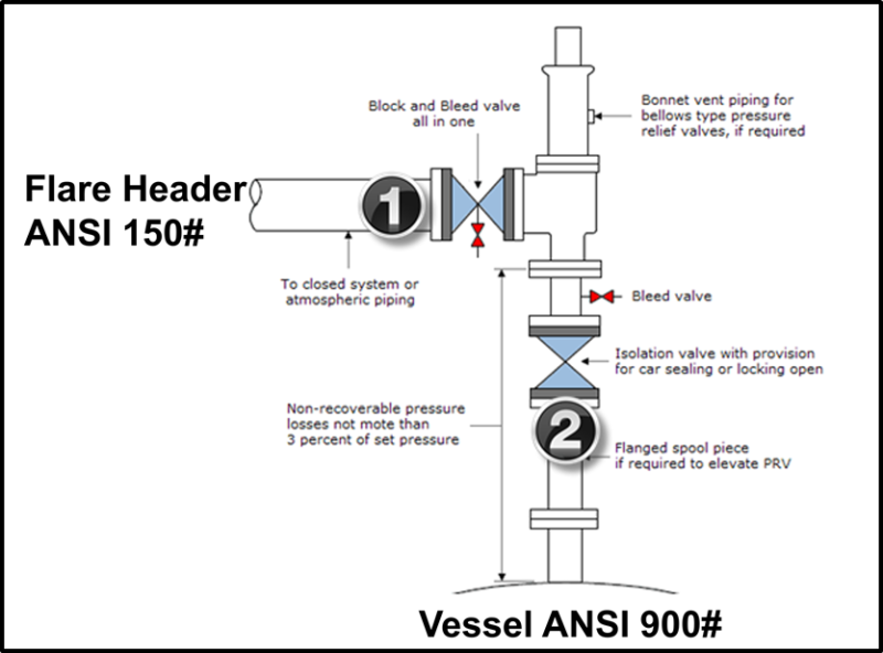
In order to ensure that the maximum allowable accumulation pressure of any system or apparatus protected by a safety valve is never exceeded, careful consideration of the safety valve’s position in the system has to be made. As there is such a wide range of applications, there is no absolute rule as to where the valve should be positioned and therefore, every application needs to be treated separately.
A common steam application for a safety valve is to protect process equipment supplied from a pressure reducing station. Two possible arrangements are shown in Figure 9.3.3.
The safety valve can be fitted within the pressure reducing station itself, that is, before the downstream stop valve, as in Figure 9.3.3 (a), or further downstream, nearer the apparatus as in Figure 9.3.3 (b). Fitting the safety valve before the downstream stop valve has the following advantages:
• The safety valve can be tested in-line by shutting down the downstream stop valve without the chance of downstream apparatus being over pressurised, should the safety valve fail under test.
• When setting the PRV under no-load conditions, the operation of the safety valve can be observed, as this condition is most likely to cause ‘simmer’. If this should occur, the PRV pressure can be adjusted to below the safety valve reseat pressure.
Indeed, a separate safety valve may have to be fitted on the inlet to each downstream piece of apparatus, when the PRV supplies several such pieces of apparatus.
• If supplying one piece of apparatus, which has a MAWP pressure less than the PRV supply pressure, the apparatus must be fitted with a safety valve, preferably close-coupled to its steam inlet connection.
• If a PRV is supplying more than one apparatus and the MAWP of any item is less than the PRV supply pressure, either the PRV station must be fitted with a safety valve set at the lowest possible MAWP of the connected apparatus, or each item of affected apparatus must be fitted with a safety valve.
• The safety valve must be located so that the pressure cannot accumulate in the apparatus viaanother route, for example, from a separate steam line or a bypass line.
It could be argued that every installation deserves special consideration when it comes to safety, but the following applications and situations are a little unusual and worth considering:
• Fire - Any pressure vessel should be protected from overpressure in the event of fire. Although a safety valve mounted for operational protection may also offer protection under fire conditions,such cases require special consideration, which is beyond the scope of this text.
• Exothermic applications - These must be fitted with a safety valve close-coupled to the apparatus steam inlet or the body direct. No alternative applies.
• Safety valves used as warning devices - Sometimes, safety valves are fitted to systems as warning devices. They are not required to relieve fault loads but to warn of pressures increasing above normal working pressures for operational reasons only. In these instances, safety valves are set at the warning pressure and only need to be of minimum size. If there is any danger of systems fitted with such a safety valve exceeding their maximum allowable working pressure, they must be protected by additional safety valves in the usual way.
In order to illustrate the importance of the positioning of a safety valve, consider an automatic pump trap (see Block 14) used to remove condensate from a heating vessel. The automatic pump trap (APT), incorporates a mechanical type pump, which uses the motive force of steam to pump the condensate through the return system. The position of the safety valve will depend on the MAWP of the APT and its required motive inlet pressure.
This arrangement is suitable if the pump-trap motive pressure is less than 1.6 bar g (safety valve set pressure of 2 bar g less 0.3 bar blowdown and a 0.1 bar shut-off margin). Since the MAWP of both the APT and the vessel are greater than the safety valve set pressure, a single safety valve would provide suitable protection for the system.
However, if the pump-trap motive pressure had to be greater than 1.6 bar g, the APT supply would have to be taken from the high pressure side of the PRV, and reduced to a more appropriate pressure, but still less than the 4.5 bar g MAWP of the APT. The arrangement shown in Figure 9.3.5 would be suitable in this situation.
Here, two separate PRV stations are used each with its own safety valve. If the APT internals failed and steam at 4 bar g passed through the APT and into the vessel, safety valve ‘A’ would relieve this pressure and protect the vessel. Safety valve ‘B’ would not lift as the pressure in the APT is still acceptable and below its set pressure.
It should be noted that safety valve ‘A’ is positioned on the downstream side of the temperature control valve; this is done for both safety and operational reasons:
Operation - There is less chance of safety valve ‘A’ simmering during operation in this position,as the pressure is typically lower after the control valve than before it.
Also, note that if the MAWP of the pump-trap were greater than the pressure upstream of PRV ‘A’, it would be permissible to omit safety valve ‘B’ from the system, but safety valve ‘A’ must be sized to take into account the total fault flow through PRV ‘B’ as well as through PRV ‘A’.
A pharmaceutical factory has twelve jacketed pans on the same production floor, all rated with the same MAWP. Where would the safety valve be positioned?
One solution would be to install a safety valve on the inlet to each pan (Figure 9.3.6). In this instance, each safety valve would have to be sized to pass the entire load, in case the PRV failed open whilst the other eleven pans were shut down.
If additional apparatus with a lower MAWP than the pans (for example, a shell and tube heat exchanger) were to be included in the system, it would be necessary to fit an additional safety valve. This safety valve would be set to an appropriate lower set pressure and sized to pass the fault flow through the temperature control valve (see Figure 9.3.8).

Butterfly Valves are available in Manual, Air Actuated, or Air Actuated with two Micro switches and a Solenoid Valve. Clamp or Weld ends are standard. Other connections are available upon request. Available seat materials include Silicone, Viton®, and EPDM. Size range from 1˝ through 6˝. All products contact surfaces are available in either T304 or T316 stainless steel.
Butterfly Valves are available in Manual, Air Actuated, or Air Actuated with proximity switches and 24V Solenoid Valve. Clamp or Weld ends are standard. Other connections are available upon request.
Available seat materials include Silicone, Viton®, and EPDM. Sizes range from 1¨ through 6¨. All product contact surfaces are available in either T304L or T316L stainless steel
Check Valves are widely used for both sanitary and industrial applications to prevent backflow of product. Ball Check Valves are designed to allow full product flow during processing. Once the product flow stops the ball rolls back to the seat at inlet preventing back flow. Ball Check Valves are commonly used with liquid products and installed horizontally. Sizes range 1 1/2¨ - 3¨.
Check Valves are widely used for both sanitary and industrial applications to prevent backflow of product. Spring Check Valves are designed to prevent fluid from flowing back and to create a positive shutoff. They are commonly used with liquid products and installed in the vertical position.
Check Valves are widely used for both sanitary and industrial applications to prevent backflow of product. Air Blow Check Valves are designed to evacuate lines of product or CIP solutions. Air Blow Check Valves are made of T316L Stainless Steel
Ball Valves are used in a wide variety of high pressure applications. Two factors make them popular. First, a full unrestricted flow that allows no product restrictions through the valve. Second, the three piece design and the removal of a minimal number of bolts allows service to be performed without removing the complete valve from the line.
Ball Valves are used in a wide variety of high pressure applications. A full unrestricted flow allows no product restrictions through the valve. Thus, allowing easy diversion.
Ball Valves are used in a wide variety of high pressure applications. A full unrestricted flow allows no product restrictions through the valve. Thus, allowing easy diversion. Ball Valves are available in Manual, Pneumatically Actuated, and Electrically Actuated versions. We also offer a full line of control options. Limit switches, Solenoids, and Positioners can be included with your automated valve assembly.
PVE Valves are available in three operating modules: Air Actuated; Air Actuated with an electronic control head; and manually operated. PVE valves popular applications are the following: Shut-off Valve, Divert Valve, Tank Outlet and Pressure Relief Valve. Connections consist of Clamp, Weld, Bevel Seat, and E-Line. EGMO’s PVE Valves are made of AISI 316L Stainless steel which meet all 3A requirements and are offered in 1˝ through 4˝ sizes. Unique patent pending sealing system.
The EGMO Sampling Valves are uniquely designed for process quality control, which often demands a stringent sampling process for the finished product and throughout the various production stages. Sampling plays a critical role in product verification. Sampling directly from the process can be risky for the operator as well as for the environment (contamination, pollution). Wherever product safety is a top priority, use ESVs to ensure stringent product quality control at every processing stage while elimination risks in the sampling procedure. With ESV, bacteriological samples can be taken directly from the pipeline.

Safety is of the utmost importance when dealing with pressure relief valves. The valve is designed to limit system pressure, and it is critical that they remain in working order to prevent an explosion. Explosions have caused far too much damage in companies over the years, and though pressurized tanks and vessels are equipped with pressure relief vales to enhance safety, they can fail and result in disaster.
That’s also why knowing the correct way to test the valves is important. Ongoing maintenance and periodic testing of pressurized tanks and vessels and their pressure relief valves keeps them in working order and keep employees and their work environments safe. Pressure relief valves must be in good condition in order to automatically lower tank and vessel pressure; working valves open slowly when the pressure gets high enough to exceed the pressure threshold and then closes slowly until the unit reaches the low, safe threshold. To ensure the pressure relief valve is in good working condition, employees must follow best practices for testing them including:
If you consider testing pressure relief valves a maintenance task, you’ll be more likely to carry out regular testing and ensure the safety of your organization and the longevity of your
It’s important to note, however, that the American Society of Mechanical Engineers (ASME) and National Board Inspection Code (NBIC), as well as state and local jurisdictions, may set requirements for testing frequency. Companies are responsible for checking with these organizations to become familiar with the testing requirements. Consider the following NBIC recommendations on the frequency for testing relief valves:
High-temperature hot water boilers (greater than 160 psi and/or 250 degrees Fahrenheit) – pressure test annually to verify nameplate set pressure. For safety reasons, removal and testing on a test bench is recommended
When testing the pressure relief valve, raise and lower the test lever several times. The lever will come away from the brass stem and allow hot water to come out of the end of the drainpipe. The water should flow through the pipe, and then you should turn down the pressure to stop the leak, replace the lever, and then increase the pressure.
One of the most common problems you can address with regular testing is the buildup of mineral salt, rust, and corrosion. When buildup occurs, the valve will become non-operational; the result can be an explosion. Regular testing helps you discover these issues sooner so you can combat them and keep your boiler and valve functioning properly. If no water flows through the pipe, or if there is a trickle instead of a rush of water, look for debris that is preventing the valve from seating properly. You may be able to operate the test lever a few times to correct the issue. You will need to replace the valve if this test fails.
When testing relief valves, keep in mind that they have two basic functions. First, they will pop off when the pressure exceeds its safety threshold. The valve will pop off and open to exhaust the excess pressure until the tank’s pressure decreases to reach the set minimum pressure. After this blowdown process occurs, the valve should reset and automatically close. One important testing safety measure is to use a pressure indicator with a full-scale range higher than the pop-off pressure.
Thus, you need to be aware of the pop-off pressure point of whatever tank or vessel you test. You always should remain within the pressure limits of the test stand and ensure the test stand is assembled properly and proof pressure tested. Then, take steps to ensure the escaping pressure from the valve is directed away from the operator and that everyone involved in the test uses safety shields and wears safety eye protection.
After discharge – Because pressure relief valves are designed to open automatically to relieve pressure in your system and then close, they may be able to open and close multiple times during normal operation and testing. However, when a valve opens, debris may get into the valve seat and prevent the valve from closing properly. After discharge, check the valve for leakage. If the leakage exceeds the original settings, you need to repair the valve.
According to local jurisdictional requirements – Regulations are in place for various locations and industries that stipulate how long valves may operate before needing to be repair or replaced. State inspectors may require valves to be disassembled, inspected, repaired, and tested every five years, for instance. If you have smaller valves and applications, you can test the valve by lifting the test lever. However, you should do this approximately once a year. It’s important to note that ASME UG136A Section 3 requires valves to have a minimum of 75% operating pressure versus the set pressure of the valve for hand lifting to be performed for these types of tests.
Depending on their service and application– The service and application of a valve affect its lifespan. Valves used for clean service like steam typically last at least 20 years if they are not operated too close to the set point and are part of a preventive maintenance program. Conversely, valves used for services such as acid service, those that are operated too close to the set point, and those exposed to dirt or debris need to be replaced more often.
Pressure relief valves serve a critical role in protecting organizations and employees from explosions. Knowing how and when to test and repair or replace them is essential.

With the STAUFF Valves product range, the companies of STAUFF Group provide access to a comprehensive range of manually operated valves for shutting off, regulating, throttling and fluid media in mobile hydraulics, industrial hydraulics and other areas of application.
The portfolio includes two-way ball valves and multi-way ball valves such as three-way ball valves and four-way ball valves of various designs and sizes made of steel or stainless steel for medium and high-pressure applications.
The product range in completed by flow control valves (such as throttle valves and check valves) for in-line assembly, manifold mounting and cartridge assembly, as well as single-station and multi-station gauge isolator valves.
For special applications, STAUFF is able to provide technically modified products that will, for example, cover extreme pressure ranges up to 800 bar /12000 PSI and temperatures up to +500°C / +930°F.
Please try again in a few minutes. If the issue persist, please contact the site owner for further assistance. Reference ID IP Address Date and Time 8bf2006c85a66667641f5dd58dcb3d35 63.210.148.230 01/30/2023 12:48 AM UTC


 8613371530291