
at what psi is the safety valve set to open in stock

As well, the compressor in the system is capable of pumping air pressure to 500 psi (3450kPa), which poses danger to both the driver and others around the vehicle.
The driver of a commercial vehicle must know that the safety valve makes the sound of a machine gun when it releases excess air pressure from the system.

In an air brake system, the first tank that receives compressed air has a safety valve that releases air if the pressure gets too high. It is usually set to open at 150 psi. If the valve must open, there is a fault in the system that should be repaired by a mechanic.
Finding a quality driving school in can be a difficult and time consuming task. driving-schools.com comprehensive database of driving schools helps you pick one that’s right for you.

In order to ensure that the maximum allowable accumulation pressure of any system or apparatus protected by a safety valve is never exceeded, careful consideration of the safety valve’s position in the system has to be made. As there is such a wide range of applications, there is no absolute rule as to where the valve should be positioned and therefore, every application needs to be treated separately.
A common steam application for a safety valve is to protect process equipment supplied from a pressure reducing station. Two possible arrangements are shown in Figure 9.3.3.
The safety valve can be fitted within the pressure reducing station itself, that is, before the downstream stop valve, as in Figure 9.3.3 (a), or further downstream, nearer the apparatus as in Figure 9.3.3 (b). Fitting the safety valve before the downstream stop valve has the following advantages:
• The safety valve can be tested in-line by shutting down the downstream stop valve without the chance of downstream apparatus being over pressurised, should the safety valve fail under test.
• When setting the PRV under no-load conditions, the operation of the safety valve can be observed, as this condition is most likely to cause ‘simmer’. If this should occur, the PRV pressure can be adjusted to below the safety valve reseat pressure.
• Any additional take-offs downstream are inherently protected. Only apparatus with a lower MAWP requires additional protection. This can have significant cost benefits.
Indeed, a separate safety valve may have to be fitted on the inlet to each downstream piece of apparatus, when the PRV supplies several such pieces of apparatus.
• If supplying one piece of apparatus, which has a MAWP pressure less than the PRV supply pressure, the apparatus must be fitted with a safety valve, preferably close-coupled to its steam inlet connection.
• If a PRV is supplying more than one apparatus and the MAWP of any item is less than the PRV supply pressure, either the PRV station must be fitted with a safety valve set at the lowest possible MAWP of the connected apparatus, or each item of affected apparatus must be fitted with a safety valve.
• The safety valve must be located so that the pressure cannot accumulate in the apparatus viaanother route, for example, from a separate steam line or a bypass line.
It could be argued that every installation deserves special consideration when it comes to safety, but the following applications and situations are a little unusual and worth considering:
• Fire - Any pressure vessel should be protected from overpressure in the event of fire. Although a safety valve mounted for operational protection may also offer protection under fire conditions,such cases require special consideration, which is beyond the scope of this text.
• Exothermic applications - These must be fitted with a safety valve close-coupled to the apparatus steam inlet or the body direct. No alternative applies.
• Safety valves used as warning devices - Sometimes, safety valves are fitted to systems as warning devices. They are not required to relieve fault loads but to warn of pressures increasing above normal working pressures for operational reasons only. In these instances, safety valves are set at the warning pressure and only need to be of minimum size. If there is any danger of systems fitted with such a safety valve exceeding their maximum allowable working pressure, they must be protected by additional safety valves in the usual way.
In order to illustrate the importance of the positioning of a safety valve, consider an automatic pump trap (see Block 14) used to remove condensate from a heating vessel. The automatic pump trap (APT), incorporates a mechanical type pump, which uses the motive force of steam to pump the condensate through the return system. The position of the safety valve will depend on the MAWP of the APT and its required motive inlet pressure.
This arrangement is suitable if the pump-trap motive pressure is less than 1.6 bar g (safety valve set pressure of 2 bar g less 0.3 bar blowdown and a 0.1 bar shut-off margin). Since the MAWP of both the APT and the vessel are greater than the safety valve set pressure, a single safety valve would provide suitable protection for the system.
However, if the pump-trap motive pressure had to be greater than 1.6 bar g, the APT supply would have to be taken from the high pressure side of the PRV, and reduced to a more appropriate pressure, but still less than the 4.5 bar g MAWP of the APT. The arrangement shown in Figure 9.3.5 would be suitable in this situation.
Here, two separate PRV stations are used each with its own safety valve. If the APT internals failed and steam at 4 bar g passed through the APT and into the vessel, safety valve ‘A’ would relieve this pressure and protect the vessel. Safety valve ‘B’ would not lift as the pressure in the APT is still acceptable and below its set pressure.
It should be noted that safety valve ‘A’ is positioned on the downstream side of the temperature control valve; this is done for both safety and operational reasons:
Operation - There is less chance of safety valve ‘A’ simmering during operation in this position,as the pressure is typically lower after the control valve than before it.
Also, note that if the MAWP of the pump-trap were greater than the pressure upstream of PRV ‘A’, it would be permissible to omit safety valve ‘B’ from the system, but safety valve ‘A’ must be sized to take into account the total fault flow through PRV ‘B’ as well as through PRV ‘A’.
A pharmaceutical factory has twelve jacketed pans on the same production floor, all rated with the same MAWP. Where would the safety valve be positioned?
One solution would be to install a safety valve on the inlet to each pan (Figure 9.3.6). In this instance, each safety valve would have to be sized to pass the entire load, in case the PRV failed open whilst the other eleven pans were shut down.
If additional apparatus with a lower MAWP than the pans (for example, a shell and tube heat exchanger) were to be included in the system, it would be necessary to fit an additional safety valve. This safety valve would be set to an appropriate lower set pressure and sized to pass the fault flow through the temperature control valve (see Figure 9.3.8).
%20Cross-Section.png)
www.controlglobal.com is using a security service for protection against online attacks. An action has triggered the service and blocked your request.
Please try again in a few minutes. If the issue persist, please contact the site owner for further assistance. Reference ID IP Address Date and Time 49aa4de84ffe7587c78dee4984bc4222 63.210.148.230 01/29/2023 05:16 PM UTC

The importance of installing the correct temperature and pressure relief valve on a water heater or hot-water storage tank cannot be overemphasized. This applies to new vessels as well as relief valve replacements. The importance of installing a valve with the correct pressure rating is common knowledge to many, but it also is crucial to install a valve with the appropriate relieving capacity rating. Many times the capacity factor is overlooked.
The code of construction of the vessel itself can play a key role in choosing the correct valve capacity. Unfortunately, the code of construction criteria is unknown to many and overlooked by others.
As the name indicates, T&P relief valves are designed to protect water heaters and hot-water storage vessels against excess temperature and excess pressure. Most valves are rated at 150 psi and 210° F, but their capacity ratings vary greatly. Sometimes, an additional T&P relief valve with a lower temperature and pressure rating (typically 180° and 100 psi) is installed in a plastic hot-water distribution system to protect the piping system itself. A T&P relief valve is, in essence, a dual device because it meets the code requirements of an individual temperature relief valve and an individual pressure relief valve.
The temperature function of the valve is controlled by an internal thermostatic element. At 210°, the internal expansion within the probe causes a piston to push against the valve’s disk. The spring is overpowered and compressed, and the water escapes between the disc and seat. The extremely hot water within the tank is forced out under pressure as cold water replenishes the discharge. The cold water rushing into the vessel lowers the water temperature, and when the temperature drops back below 210°, the valve is reseated.
The pressure function of the valve also is controlled by the spring, disc and seat. When the pressure exceeds the valve’s pressure rating, the water pressure overcomes the spring. The spring is compressed (just like a typical pressure-only relief valve) and the water escapes between the disc and seat.
It is important to note that when the valve is weeping or dripping, the cause is usually excessive pressure. Many times this is caused by thermal expansion. A T&P relief valve is not designed to nor should it be used to continuously control thermal expansion within a closed system. Thermal expansion of hot water within a closed system should be controlled with the installation of an approved expansion tank or by other means permitted by local code.
Dripping may continue because of debris within the valve, such as a build-up of calcium in the seat, and over time, large mineral deposits can make the valve ineffective. When a valve is discharging a large quantity of water, the cause is almost always excessive temperature.
The only way to determine the maximum allowable working pressure of a vessel is to read the nameplate that is attached to it. The pressure on the valve’s tag must be compared to the pressure on the vessel’s nameplate. The pressure rating of the relief valve must be equal to or less than the MAWP of the vessel. Most water heaters have an MAWP of 150 psi; however, some are rated higher, typically 160 psi. Some storage vessels have a lower pressure rating; they are commonly rated 125 psi.
Another factor in determining the pressure rating of the T&P relief valve is the code itself. Model codes require the T&P relief valve be set no higher than 150 psi. Therefore, a water heater with a MAWP of 160 psi still requires a T&P relief valve set at 150 psi, even though the vessel is designed and built to withstand a higher pressure.
The relieving capacity of the valve must be equal to or greater than the Btu/hr. of the vessel. The thermal capacity of the water heater can be found on its nameplate along with the MAWP. The confusion in choosing the correct T&P relief valve resides on the relief valve’s nametag itself. T&P relief valves display two relieving capacity ratings. One is the American Society of Mechanical Engineers/National Board of Boiler and Pressure Vessel Inspectors rating, and the other is the Canadian Standards Association/American National Standards Institute Z21.22 rating.
The relieving capacity of the valve’s ASME/NB rating is established by Section IV, Part HG of the “ASME Boiler and Pressure Vessel Code.” The code reads, “Capacity certification tests of safety relief valves for water heating and hot-water supply boilers shall be conducted at 110% of the pressure for which the valve is set to operate.” So the capacity of a T&P relief valve set at 150 psi is based on its vessel pressurized to 165 psi.
The ASME/NB relieving capacity rating is more lenient than the CSA rating. The CSA rating is based on 15 psi of steam pressure, so the CSA rating will always be lower and, therefore, more stringent than the ASME/NB rating. ASME HLW water heaters are built to a more stringent code of construction than ANSI Z21 water heaters. The use of a valve’s ASME/NB capacity rating to protect an ANSI-built vessel could present a potentially dangerous condition.
Chapter 5, Section 504.4 of the 2012 International Plumbing Code specifically requires relief valves to conform to the Z21.22 standard; the code is very concise. Some of the other model codes are not as clear as the IPC. Section 504 of the Uniform Plumbing Code only references an approved, listed device installed in accordance with the listing and the manufacturer’s installation instructions; however, the Z21.22 standard is included in Table 1401.1.
While the 2012 National Standard Plumbing Code makes no distinction between the use of the ASME/NB and CSA capacity ratings, the 2015 NSPC will limit the use of the ASME/NB relieving capacity ratings to ASME vessels only.
If permitted by the local adopted code, AMSE/NB relieving capacities should only be considered for ASME vessels. The more restrictive CSA relieving capacities are always the safer choice.

A question we commonly receive is why a valve appears to open, or actuate, earlier than expected. Often, we find that the valve is not, in fact, opening early. Rather, the perception that it is actuating early is due to a misunderstanding of set pressure.
The set pressure, also called the opening pressure, of a safety or relief valve is the inlet pressure at which the valve begins to open as required by code.
A valve should be set to open at the maximum allowable working pressure (MAWP) of the vessel the valve is intended to protect. There is some tolerance to actual set pressure, which means that a valve set at 100 psig may open slightly above or slightly below this level.
The first step is to determine if your valve really is opening early. Sometimes safety and safety relief valves appear to open before they reach the set pressure — there may be an audible or visible release of fluid between the seat and the disc. This is known as “simmer” or “warn,” and it is not the same as a full open.
Simmer, or warn, occurs when a valve opens slightly, discharging only a small percentage of its rated capacity. For example, direct spring-operated safety valves may simmer or warn at 90% of the nameplate set pressure. A valve that is simmering is not considered open.
The next step is to check your gauge to ensure that it is reporting the set pressure correctly. The gauge should be calibrated properly and located upstream of the valve, close to the valve inlet. Rapid increases in system pressure can make it appear that a valve is opening early because the gauge can’t accurately report the pressure.
If you still believe your valve is opening early, assess the operating factors that might be contributing to the situation. Valves are factory set using standard conditions, and factors like high temperature, vibration, and back pressure can cause them to open early. These conditions can be compensated for using cold set pressure, aka cold differential test pressure (CDTP). Learn more about CDTP from the National Board.

The Model 7000 is a pressure relief valve specifically designed to relieve excess pressure caused by pressure surges or temperature changes in all wet fire sprinkler systems. Model 7000 pressure relief valves comply with NFPA 13 requirements stipulating that a pressure relief valve must be installed on all wet systems and downstream of all pressure-reducing valves. Model 7000s feature a bronze body, stainless steel spring, and flushing handle to remove debris. The Model 7000 can be purchased individually or as part of the TESTanDRAIN Kit with all necessary drainage piping and connections for use with all AGF TESTanDRAIN valves. Pressure relief valves can be installed on a TESTanDRAIN valve without removing the valve from the line or draining the system completely. The 7000 features a 1/2" MIPT inlet and FIPT outlet and is UL Listed and FM Approved. It is rated for 175 PSI Systems. Other Ratings Available: 205, and 250. Please specify PSI when ordering.
UL and FM standards for sprinkler system pressure relief valves require relief valves to operate within a range of their ratings. FM requires a relief valve to OPEN at a pressure no less than 85% of their rating and UL requires OPENING at a pressure no greater than 105% of their rating. Both standards require the relief valves to CLOSE within a percentage below OPEN. Choose the relief valve comparing static pressure to 90% of the relief valve"s rating to determine the estimated minimum OPENING and 80% of the relief valve"s rating for the approximate maximum CLOSING. The relief valve should be installed where it is easily accessible for maintenance. Care should be taken that the relief valve CANNOT be isolated from the system when the system is operational. A relief valve should NEVER have a shutoff valve or a plug downstream of its outlet.

This website is using a security service to protect itself from online attacks. The action you just performed triggered the security solution. There are several actions that could trigger this block including submitting a certain word or phrase, a SQL command or malformed data.

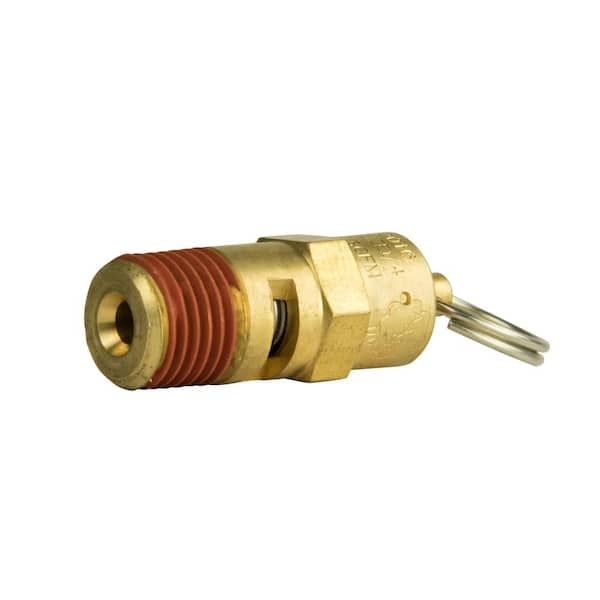
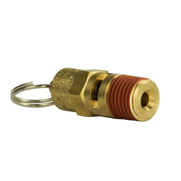
Brand new, certified 1/8" Male NPT Threaded 70 PSI air compressor / tank pressure safety relief valve. Also known as a "Pop Off" or "Blow Off" valve. This relief valve is manufactured in the United States and is stamped with "UV" & "NB" symbols. The relief pressure of this valve is set at 70 PSI and is accurate within + or - 3% of the set pressure.
A fire-tube boiler can be fitted with one or more safety valves on the top of its shell, with each set to open when the boiler reaches its design pressure. Noisolation valvesor restrictions should be integrated between the safety valve(s) and boiler. If the valves are not installed directly onto the boiler shell, the pipework connecting the valves to the boiler must be kept clear of blockagesand water, and this must be confirmed by periodic testing.
Once a safety valve opens, steam is discharged via the exhaust pipe. Exhaust pipes must be designed to encounter as few bends as possible, be as short as possible, to have no reduction in pipe section (no internal pipe diameter reduction), and should lead to asafe point of discharge(typically outside the boiler house).
Water must be drained from the safety valve or exhaust pipework via a drainpipe. Drainpipes may be connected to holes drilled into the lowest section of the exhaust pipework, or, directly to drain holes in the safety valve body; these drains are not to be confused with the blowdown ring locking bolt, if one is fitted.
Where two safety valves are fitted, it is common that one is set just belowthe boiler’s design pressure. It is vital that each safety valve permits the full flow of steam produced when the boiler is operating at maximum capacity i.e. when the boiler is producing the maximum amount of steam it can possibly produce. If safety valves are sized correctly, a boiler can be firing at full capacity without the steam pressure exceeding design limits (because the safety valve(s) relieves pressure at a faster rate than it is accumulated).
There are various types of safety valve, including high lift and improved high lift valves, which use the force of escaping steam to open a winged valve plug to achieve greater steam flow rates. In addition to this, some valves integrate a pistonat the bottom of the spring chamber. The piston has a larger surface area than the valve plug, which leads to the valve opening with a definitive ‘pop’ sound.
Some boiler safety valves include a blowdown ring. The blowdown ring can raise or lower the valve seat ring and is used to control the amount of blowdown through the valve. This ring is locked by a bolt that protrudes through the valve and into the adjusting ring segments.
Boiler safety valves should be fitted with an easing gear (looks like a handle), used, when necessary, to rapidly release boiler pressure. Easing gears can also be used for testing a safety valve, ensuring the spindle has freedom of movement and that the valve operating mechanism functions as intended. Easing gear testing is often not conducted due to operators having difficulty with the valves resealing, but this is generally only the case with valves that are not tested often enough. Actuating the easing gear several times is often all it takes to dislodge debris from the sealing area and allow the valve to seal again. For safe operation, the easing gear handle is usually connected via steel cables to an area neighbouring the boiler.
Like pressure gauges, all safety valves should be stripped, inspected, and calibrated, at least once a year; maintenance usually occurs during statutory inspections. Calibration of each valve should be conducted by a competent person, and any valve adjustment (including the blowdown ring) should be approved and sealed by the authorised inspector. After testing and calibration, all valves should be correctly marked, suitable certificates issued, and accurate records maintained.
An accumulation test can be conducted to ensure a safety valve can relieve over-pressure steam when the boiler burner is operating at maximum capacity. Accumulation testing of safety valves must be repeated after any alterations are made to the boiler e.g. replacement of a safety valve, fuel change, or changes to the control system. If, during an accumulation test, boiler pressure rises by more than 10% of its design pressure, the test must be aborted. Before the boiler is re-tested, amendments must be made to either the safety valve relieving capacity, thesafety valve exhaust pipework, or the boiler’s steaming capacity, to ensure the 10% limit is never exceeded.
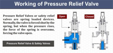
Reliefand safetyvalves prevent equipment damage by relieving over-pressurisation of fluid systems. The main difference between a relief valve and a safety valve is the extent of opening at the set-point pressure.
A relief valve gradually opens as the inlet pressure increases above the set-point. A relief valve opens only as necessary to relieve the over-pressure condition. Relief valves are typically used for liquid systems.
A safety valve rapidly‘pops’ fully openas soon as the pressure setting is reached and will stay fully open until the pressure drops below the reset pressure. The reset pressure is lower than the actuating set-point pressure. The difference between the actuating pressure set-point, and the pressure at which the safety valve resets, is called blowdown. Safety valves are typically used for gas or vapour systems.
A safety relief valve may open fully, or proportionally, once the pressure setting is reached. SRVs may be used for any fluid system (gas, liquid, or vapour).
This website is using a security service to protect itself from online attacks. The action you just performed triggered the security solution. There are several actions that could trigger this block including submitting a certain word or phrase, a SQL command or malformed data.


 8613371530291