
at what psi is the safety valve set to open free sample

In an air brake system, the first tank that receives compressed air has a safety valve that releases air if the pressure gets too high. It is usually set to open at 150 psi. If the valve must open, there is a fault in the system that should be repaired by a mechanic.

Finding a quality driving school in can be a difficult and time consuming task. driving-schools.com comprehensive database of driving schools helps you pick one that’s right for you.

As well, the compressor in the system is capable of pumping air pressure to 500 psi (3450kPa), which poses danger to both the driver and others around the vehicle.
The driver of a commercial vehicle must know that the safety valve makes the sound of a machine gun when it releases excess air pressure from the system.
A little product education can make you look super smart to customers, which usually means more orders for everything you sell. Here’s a few things to keep in mind about safety valves, so your customers will think you’re a genius.
A safety valve is required on anything that has pressure on it. It can be a boiler (high- or low-pressure), a compressor, heat exchanger, economizer, any pressure vessel, deaerator tank, sterilizer, after a reducing valve, etc.
There are four main types of safety valves: conventional, bellows, pilot-operated, and temperature and pressure. For this column, we will deal with conventional valves.
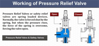
A safety valve is a simple but delicate device. It’s just two pieces of metal squeezed together by a spring. It is passive because it just sits there waiting for system pressure to rise. If everything else in the system works correctly, then the safety valve will never go off.
A safety valve is NOT 100% tight up to the set pressure. This is VERY important. A safety valve functions a little like a tea kettle. As the temperature rises in the kettle, it starts to hiss and spit when the water is almost at a boil. A safety valve functions the same way but with pressure not temperature. The set pressure must be at least 10% above the operating pressure or 5 psig, whichever is greater. So, if a system is operating at 25 psig, then the minimum set pressure of the safety valve would be 30 psig.
Most valve manufacturers prefer a 10 psig differential just so the customer has fewer problems. If a valve is positioned after a reducing valve, find out the max pressure that the equipment downstream can handle. If it can handle 40 psig, then set the valve at 40. If the customer is operating at 100 psig, then 110 would be the minimum. If the max pressure in this case is 150, then set it at 150. The equipment is still protected and they won’t have as many problems with the safety valve.
Here’s another reason the safety valve is set higher than the operating pressure: When it relieves, it needs room to shut off. This is called BLOWDOWN. In a steam and air valve there is at least one if not two adjusting rings to help control blowdown. They are adjusted to shut the valve off when the pressure subsides to 6% below the set pressure. There are variations to 6% but for our purposes it is good enough. So, if you operate a boiler at 100 psig and you set the safety valve at 105, it will probably leak. But if it didn’t, the blowdown would be set at 99, and the valve would never shut off because the operating pressure would be greater than the blowdown.
All safety valves that are on steam or air are required by code to have a test lever. It can be a plain open lever or a completely enclosed packed lever.
Safety valves are sized by flow rate not by pipe size. If a customer wants a 12″ safety valve, ask them the flow rate and the pressure setting. It will probably turn out that they need an 8×10 instead of a 12×16. Safety valves are not like gate valves. If you have a 12″ line, you put in a 12″ gate valve. If safety valves are sized too large, they will not function correctly. They will chatter and beat themselves to death.
Safety valves need to be selected for the worst possible scenario. If you are sizing a pressure reducing station that has 150 psig steam being reduced to 10 psig, you need a safety valve that is rated for 150 psig even though it is set at 15. You can’t put a 15 psig low-pressure boiler valve after the reducing valve because the body of the valve must to be able to handle the 150 psig of steam in case the reducing valve fails.
The seating surface in a safety valve is surprisingly small. In a 3×4 valve, the seating surface is 1/8″ wide and 5″ around. All it takes is one pop with a piece of debris going through and it can leak. Here’s an example: Folgers had a plant in downtown Kansas City that had a 6×8 DISCONTINUED Consolidated 1411Q set at 15 psig. The valve was probably 70 years old. We repaired it, but it leaked when plant maintenance put it back on. It was after a reducing valve, and I asked him if he played with the reducing valve and brought the pressure up to pop the safety valve. He said no, but I didn’t believe him. I told him the valve didn’t leak when it left our shop and to send it back.
When it came back, I laid it down on the outlet flange and looked up the inlet. There was a 12″ welding rod with the tip stuck between the seat and the disc. That rod was from the original construction and didn’t get blown out properly and just now it got set free. The maintenance guy didn’t believe me and came over and saw it for himself (this was before cell phones when you could take a picture).
If there is a problem with a safety valve, 99% of the time it is not the safety valve or the company that set it. There may be other reasons that the pressure is rising in the system before the safety valve. Some ethanol plants have a problem on starting up their boilers. The valves are set at 150 and they operate at 120 but at startup the pressure gets away from them and there is a spike, which creates enough pressure to cause a leak until things get under control.
If your customer is complaining that the valve is leaking, ask questions before a replacement is sent out. What is the operating pressure below the safety valve? If it is too close to the set pressure then they have to lower their operating pressure or raise the set pressure on the safety valve.
Is the valve installed in a vertical position? If it is on a 45-degree angle, horizontal, or upside down then it needs to be corrected. I have heard of two valves that were upside down in my 47 years. One was on a steam tractor and the other one was on a high-pressure compressor station in the New Mexico desert. He bought a 1/4″ valve set at 5,000 psig. On the outlet side, he left the end cap in the outlet and put a pin hole in it so he could hear if it was leaking or not. He hit the switch and when it got up to 3,500 psig the end cap came flying out like a missile past his nose. I told him to turn that sucker in the right direction and he shouldn’t have any problems. I never heard from him so I guess it worked.
If the set pressure is correct, and the valve is vertical, ask if the outlet piping is supported by something other than the safety valve. If they don’t have pipe hangers or a wall or something to keep the stress off the safety valve, it will leak.
There was a plant in Springfield, Mo. that couldn’t start up because a 2″ valve was leaking on a tank. It was set at 750 psig, and the factory replaced it 5 times. We are not going to replace any valves until certain questions are answered. I was called to solve the problem. The operating pressure was 450 so that wasn’t the problem. It was in a vertical position so we moved on to the piping. You could tell the guy was on his cell phone when I asked if there was any piping on the outlet. He said while looking at the installation that he had a 2″ line coming out into a 2×3 connection going up a story into a 3×4 connection and going up another story. I asked him if there was any support for this mess, and he hung up the phone. He didn’t say thank you, goodbye, or send me a Christmas present.
Pipe dope is another problem child. Make sure your contractors ease off on the pipe dope. That is enough for today, class. Thank you for your patience. And thank you for your business.

A question we commonly receive is why a valve appears to open, or actuate, earlier than expected. Often, we find that the valve is not, in fact, opening early. Rather, the perception that it is actuating early is due to a misunderstanding of set pressure.
The set pressure, also called the opening pressure, of a safety or relief valve is the inlet pressure at which the valve begins to open as required by code.
A valve should be set to open at the maximum allowable working pressure (MAWP) of the vessel the valve is intended to protect. There is some tolerance to actual set pressure, which means that a valve set at 100 psig may open slightly above or slightly below this level.
The first step is to determine if your valve really is opening early. Sometimes safety and safety relief valves appear to open before they reach the set pressure — there may be an audible or visible release of fluid between the seat and the disc. This is known as “simmer” or “warn,” and it is not the same as a full open.
Simmer, or warn, occurs when a valve opens slightly, discharging only a small percentage of its rated capacity. For example, direct spring-operated safety valves may simmer or warn at 90% of the nameplate set pressure. A valve that is simmering is not considered open.
The next step is to check your gauge to ensure that it is reporting the set pressure correctly. The gauge should be calibrated properly and located upstream of the valve, close to the valve inlet. Rapid increases in system pressure can make it appear that a valve is opening early because the gauge can’t accurately report the pressure.
If you still believe your valve is opening early, assess the operating factors that might be contributing to the situation. Valves are factory set using standard conditions, and factors like high temperature, vibration, and back pressure can cause them to open early. These conditions can be compensated for using cold set pressure, aka cold differential test pressure (CDTP). Learn more about CDTP from the National Board.

In order to ensure that the maximum allowable accumulation pressure of any system or apparatus protected by a safety valve is never exceeded, careful consideration of the safety valve’s position in the system has to be made. As there is such a wide range of applications, there is no absolute rule as to where the valve should be positioned and therefore, every application needs to be treated separately.
A common steam application for a safety valve is to protect process equipment supplied from a pressure reducing station. Two possible arrangements are shown in Figure 9.3.3.
The safety valve can be fitted within the pressure reducing station itself, that is, before the downstream stop valve, as in Figure 9.3.3 (a), or further downstream, nearer the apparatus as in Figure 9.3.3 (b). Fitting the safety valve before the downstream stop valve has the following advantages:
• The safety valve can be tested in-line by shutting down the downstream stop valve without the chance of downstream apparatus being over pressurised, should the safety valve fail under test.
• When setting the PRV under no-load conditions, the operation of the safety valve can be observed, as this condition is most likely to cause ‘simmer’. If this should occur, the PRV pressure can be adjusted to below the safety valve reseat pressure.
• Any additional take-offs downstream are inherently protected. Only apparatus with a lower MAWP requires additional protection. This can have significant cost benefits.
Indeed, a separate safety valve may have to be fitted on the inlet to each downstream piece of apparatus, when the PRV supplies several such pieces of apparatus.
• If supplying one piece of apparatus, which has a MAWP pressure less than the PRV supply pressure, the apparatus must be fitted with a safety valve, preferably close-coupled to its steam inlet connection.
• If a PRV is supplying more than one apparatus and the MAWP of any item is less than the PRV supply pressure, either the PRV station must be fitted with a safety valve set at the lowest possible MAWP of the connected apparatus, or each item of affected apparatus must be fitted with a safety valve.
• The safety valve must be located so that the pressure cannot accumulate in the apparatus viaanother route, for example, from a separate steam line or a bypass line.
It could be argued that every installation deserves special consideration when it comes to safety, but the following applications and situations are a little unusual and worth considering:
• Fire - Any pressure vessel should be protected from overpressure in the event of fire. Although a safety valve mounted for operational protection may also offer protection under fire conditions,such cases require special consideration, which is beyond the scope of this text.
• Exothermic applications - These must be fitted with a safety valve close-coupled to the apparatus steam inlet or the body direct. No alternative applies.
• Safety valves used as warning devices - Sometimes, safety valves are fitted to systems as warning devices. They are not required to relieve fault loads but to warn of pressures increasing above normal working pressures for operational reasons only. In these instances, safety valves are set at the warning pressure and only need to be of minimum size. If there is any danger of systems fitted with such a safety valve exceeding their maximum allowable working pressure, they must be protected by additional safety valves in the usual way.
In order to illustrate the importance of the positioning of a safety valve, consider an automatic pump trap (see Block 14) used to remove condensate from a heating vessel. The automatic pump trap (APT), incorporates a mechanical type pump, which uses the motive force of steam to pump the condensate through the return system. The position of the safety valve will depend on the MAWP of the APT and its required motive inlet pressure.
This arrangement is suitable if the pump-trap motive pressure is less than 1.6 bar g (safety valve set pressure of 2 bar g less 0.3 bar blowdown and a 0.1 bar shut-off margin). Since the MAWP of both the APT and the vessel are greater than the safety valve set pressure, a single safety valve would provide suitable protection for the system.
However, if the pump-trap motive pressure had to be greater than 1.6 bar g, the APT supply would have to be taken from the high pressure side of the PRV, and reduced to a more appropriate pressure, but still less than the 4.5 bar g MAWP of the APT. The arrangement shown in Figure 9.3.5 would be suitable in this situation.
Here, two separate PRV stations are used each with its own safety valve. If the APT internals failed and steam at 4 bar g passed through the APT and into the vessel, safety valve ‘A’ would relieve this pressure and protect the vessel. Safety valve ‘B’ would not lift as the pressure in the APT is still acceptable and below its set pressure.
It should be noted that safety valve ‘A’ is positioned on the downstream side of the temperature control valve; this is done for both safety and operational reasons:
Operation - There is less chance of safety valve ‘A’ simmering during operation in this position,as the pressure is typically lower after the control valve than before it.
Also, note that if the MAWP of the pump-trap were greater than the pressure upstream of PRV ‘A’, it would be permissible to omit safety valve ‘B’ from the system, but safety valve ‘A’ must be sized to take into account the total fault flow through PRV ‘B’ as well as through PRV ‘A’.
A pharmaceutical factory has twelve jacketed pans on the same production floor, all rated with the same MAWP. Where would the safety valve be positioned?
One solution would be to install a safety valve on the inlet to each pan (Figure 9.3.6). In this instance, each safety valve would have to be sized to pass the entire load, in case the PRV failed open whilst the other eleven pans were shut down.
If additional apparatus with a lower MAWP than the pans (for example, a shell and tube heat exchanger) were to be included in the system, it would be necessary to fit an additional safety valve. This safety valve would be set to an appropriate lower set pressure and sized to pass the fault flow through the temperature control valve (see Figure 9.3.8).
Boiler explosions have been responsible for widespread damage to companies throughout the years, and that’s why today’s boilers are equipped with safety valves and/or relief valves. Boiler safety valves are designed to prevent excess pressure, which is usually responsible for those devastating explosions. That said, to ensure that boiler safety valves are working properly and providing adequate protection, they must meet regulatory specifications and require ongoing maintenance and periodic testing. Without these precautions, malfunctioning safety valves may fail, resulting in potentially disastrous consequences.
Boiler safety valves are activated by upstream pressure. If the pressure exceeds a defined threshold, the valve activates and automatically releases pressure. Typically used for gas or vapor service, boiler safety valves pop fully open once a pressure threshold is reached and remain open until the boiler pressure reaches a pre-defined, safe lower pressure.
Boiler relief valves serve the same purpose – automatically lowering boiler pressure – but they function a bit differently than safety valves. A relief valve doesn’t open fully when pressure exceeds a defined threshold; instead, it opens gradually when the pressure threshold is exceeded and closes gradually until the lower, safe threshold is reached. Boiler relief valves are typically used for liquid service.
There are also devices known as “safety relief valves” which have the characteristics of both types discussed above. Safety relief valves can be used for either liquid or gas or vapor service.
Nameplates must be fastened securely and permanently to the safety valve and remain readable throughout the lifespan of the valve, so durability is key.
The National Board of Boiler and Pressure Vessel Inspectors offers guidance and recommendations on boiler and pressure vessel safety rules and regulations. However, most individual states set forth their own rules and regulations, and while they may be similar across states, it’s important to ensure that your boiler safety valves meet all state and local regulatory requirements.
The National Board published NB-131, Recommended Boiler and Pressure Vessel Safety Legislation, and NB-132, Recommended Administrative Boiler and Pressure Vessel Safety Rules and Regulationsin order to provide guidance and encourage the development of crucial safety laws in jurisdictions that currently have no laws in place for the “proper construction, installation, inspection, operation, maintenance, alterations, and repairs” necessary to protect workers and the public from dangerous boiler and pressure vessel explosions that may occur without these safeguards in place.
The documents are meant to be used as a guide for developing local laws and regulations and also may be used to update a jurisdiction’s existing requirements. As such, they’re intended to be modifiable to meet any jurisdiction’s local conditions.
The American Society of Mechanical Engineers (ASME) governs the code that establishes guidelines and requirements for safety valves. Note that it’s up to plant personnel to familiarize themselves with the requirements and understand which parts of the code apply to specific parts of the plant’s steam systems.
High steam capacity requirements, physical or economic constraints may make the use of a single safety valve impossible. In these cases, using multiple safety valves on the same system is considered an acceptable practice, provided that proper sizing and installation requirements are met – including an appropriately sized vent pipe that accounts for the total steam venting capacity of all valves when open at the same time.
The lowest rating (MAWP or maximum allowable working pressure) should always be used among all safety devices within a system, including boilers, pressure vessels, and equipment piping systems, to determine the safety valve set pressure.
General guidance on proper installation may seem like common sense to experienced installers and inspectors. A few of the most important guidelines and best practices include:
Avoid isolating safety valves from the system, such as by installing intervening shut-off valves located between the steam component or system and the inlet.
Contact the valve supplier immediately for any safety valve with a broken wire seal, as this indicates that the valve is unsafe for use. Safety valves are sealed and certified in order to prevent tampering that can prevent proper function.
Avoid attaching vent discharge piping directly to a safety valve, which may place unnecessary weight and additional stress on the valve, altering the set pressure.

(a) Qualifications of individual who adjusts. Safety relief valves shall be set and adjusted by a competent person who is thoroughly familiar with the construction and operation of the valve being set.
(b) Opening pressures. At least one safety relief valve shall be set to open at a pressure not exceeding the MAWP. Safety relief valves shall be set to open at pressures not exceeding 6 psi above the MAWP.
(c) Setting procedures. When setting safety relief valves, two steam gauges shall be used, one of which must be so located that it will be in full view of the persons engaged in setting such valves; and if the pressure indicated by the gauges varies more than 3 psi they shall be removed from the boiler, tested, and corrected before the safety relief valves are set. Gauges shall in all cases be tested immediately before the safety relief valves are set or any change made in the setting. When setting safety relief valves, the water level shall not be higher than
(d) Labeling of lowest set pressure. The set pressure of the lowest safety relief valve shall be indicated on a tag or label attached to the steam gauge so that it may be clearly read while observing the steam gauge.
(a) Each cargo tank must be equipped to relieve pressure and vacuum conditions in conformance with this section and the applicable individual specification. The pressure and vacuum relief system must be designed to operate and have sufficient capacity to prevent cargo tank rupture or collapse due to over-pressurization or vacuum resulting from loading, unloading, or from heating and cooling of lading. Pressure relief systems are not required to conform to the ASME Code.
(1) Each cargo tank must be provided with a primary pressure relief system consisting of one or more reclosing pressure relief valves. A secondary pressure relief system consisting of another pressure relief valve in parallel with the primary pressure relief system may be used to augment the total venting capacity of the cargo tank. Non-reclosing pressure relief devices are not authorized in any cargo tank except when in series with a reclosing pressure relief device. Gravity actuated reclosing valves are not authorized on any cargo tank.
(2) When provided by § 173.33(c)(1)(iii) of this subchapter, cargo tanks may be equipped with a normal vent. Such vents must be set to open at not less than 1 psig and must be designed to prevent loss of lading through the device in case of vehicle overturn.
(3) Each pressure relief system must be designed to withstand dynamic pressure surges in excess of the design set pressure as specified in paragraphs (b)(3) (i) and (ii) of this section. Set pressure is a function of MAWP as set forth in paragraph (d) of this section.
(i) Each pressure relief device must be able to withstand dynamic pressure surge reaching 30 psig above the design set pressure and sustained above the set pressure for at least 60 milliseconds with a total volume of liquid released not exceeding one gallon before the relief device recloses to a leak-tight condition. This requirement must be met regardless of vehicle orientation. This capability must be demonstrated by testing. An acceptable method is outlined in TTMA RP No. 81-97 “Performance of Spring Loaded Pressure Relief Valves on MC 306, MC 307, MC 312, DOT 406, DOT 407, and DOT 412 Tanks” (incorporated by reference; see § 171.7 of this subchapter).
(ii) After August 31, 1995, each pressure relief device must be able to withstand a dynamic pressure surge reaching 30 psig above the design set pressure and sustained above the design set pressure for at least 60 milliseconds with a total volume of liquid released not exceeding 1 L before the relief valve recloses to a leak-tight condition. This requirement must be met regardless of vehicle orientation. This capability must be demonstrated by testing. TTMA RP No. 81, cited in paragraph (b)(3)(i) of this section, is an acceptable test procedure.
(4) Each reclosing pressure relief valve must be constructed and installed in such a manner as to prevent unauthorized adjustment of the relief valve setting.
(6) The pressure relief system must be mounted, shielded and drainable so as to minimize the accumulation of material that could impair the operation or discharge capability of the system by freezing, corrosion or blockage.
(c) Location of relief devices. Each pressure relief device must communicate with the vapor space above the lading as near as practicable to the center of the vapor space. For example, on a cargo tank designed to operate in a level attitude, the device should be positioned at the horizontal and transverse center of the cargo tank; on cargo tanks sloped to the rear, the device should be located in the forward half of the cargo tank. The discharge from any device must be unrestricted. Protective devices which deflect the flow of vapor are permissible provided the required vent capacity is maintained.
(d) Settings of pressure relief system. The set pressure of the pressure relief system is the pressure at which it starts to open, allowing discharge.
(1) Primary pressure relief system. The set pressure of each primary relief valve must be no less than 120 percent of the MAWP, and no more than 132 percent of the MAWP. The valve must reclose at not less than 108 percent of the MAWP and remain closed at lower pressures.
(2) Secondary pressure relief system. The set pressure of each pressure relief valve used as a secondary relief device must be not less than 120 percent of the MAWP.
(e) Venting capacity of pressure relief systems. The pressure relief system (primary and secondary, including piping) must have sufficient venting capacity to limit the cargo tank internal pressure to not more than the cargo tank test pressure. The total venting capacity, rated at not more than the cargo tank test pressure, must be at least that specified in table I, except as provided in § 178.348-4.
(1) Primary pressure relief system. Unless otherwise specified in the applicable individual specification, the primary relief system must have a minimum venting capacity of 12,000 SCFH per 350 square feet of exposed cargo tank area, but in any case at least one fourth the required total venting capacity for the cargo tank.
(2) Secondary pressure relief system. If the primary pressure relief system does not provide the required total venting capacity, additional capacity must be provided by a secondary pressure relief system.
(f) Certification of pressure relief devices. The manufacturer of any pressure relief device, including valves, frangible (rupture) disks, vacuum vents and combination devices must certify that the device model was designed and tested in accordance with this section and the appropriate cargo tank specification. The certificate must contain sufficient information to describe the device and its performance. The certificate must be signed by a responsible official of the manufacturer who approved the flow capacity certification.
(g) Rated flow capacity certification test. Each pressure relief device model must be successfully flow capacity certification tested prior to first use. Devices having one design, size and set pressure are considered to be one model. The testing requirements are as follows:
(1) At least 3 devices of each specific model must be tested for flow capacity at a pressure not greater than the test pressure of the cargo tank. For a device model to be certified, the capacities of the devices tested must fall within a range of plus or minus 5 percent of the average for the devices tested.
[Amdt. 178-89, 54 FR 25025, June 12, 1989, as amended at 55 FR 21038, May 22, 1990; 55 FR 37062, Sept. 7, 1990; Amdt. 178-89, 56 FR 27877, June 17, 1991; Amdt. 178-105, 59 FR 55175, Nov. 3, 1994; Amdt. 178-118, 61 FR 51341, Oct. 1, 1996; 65 FR 58631, Sept. 29, 2000; 66 FR 45389, Aug. 28, 2001; 68 FR 19284, Apr. 18, 2003]
Industrial equipment often uses either safety or relief valves to prevent damaging pressure levels from building up. Though they perform similar functions, there are some critical differences between safety and relief valves. Understanding these two valves’ differences is essential for proper pressure system operation. So here we discuss the pressure safety valve vs pressure relief valve.
A pressure relief valve is a device that releases pressure from a system. The relief valve is generally immune to the effects of back pressure and must be periodically stripped down. Pressure relief valves are one the essential parts of a pressure system to prevent system failures. They are set to open at a predetermined pressure level. Each pressure system has a setpoint that is a predetermined limit. The setpoint determines when the valve will open and prevents overpressure.
Pressure relief valves are typically used in gas or liquid systems where there is a need to prevent excessive pressure from building up. When the pressure in the system reaches a certain level, the valve will open and release the pressure. Pressure relief valves are an essential safety feature in many designs and can help to prevent damage to the system or components.
PRVs are generally considered to be safe and reliable devices. However, before installing a PRV in a system, some potential disadvantages should be considered. Here are five pros and cons of pressure relief valves:
Pros: Pressure relief valves are anessential safety feature in many systems. They protect against over-pressurization by relieving excess pressure from the system. This can help to prevent severe damage or even explosions.
Pressure relief valves can help to improve the efficiency of a system. The system can operate at lower overall pressure by relieving excess pressure and saving energy.
Pressure relief valves can be used as a safety device in systems that are susceptible to overpressurization. By relieving pressure before it builds up to a dangerous level, they can help to prevent accidents and injuries.
Cons: Pressure relief valves can be a potential source of leaks. If not properly maintained, the valve may not seat properly and can allow fluids or gasses to escape.
Pressure relief valves can sometimes cause problems if they do not open or close properly. This can lead to process disruptions and may cause safety issues.
A pressure safety valve is a device used to release pressure from a system that has exceeded its design limit. This safety valve is a fail-safe device. This type of valve is typically used in systems that contain fluids or gasses under high pressure. Pressure safety valves are designed to open and release pressure when the system has exceeded its maximum pressure limit. This helps to prevent the system from rupturing or exploding.
Pressure safety valves are an essential part of many different types of systems and can help keep both people and property safe. If anyone is ever in a situation where they need to release pressure from a system, it is essential to know how to use a pressure safety valve correctly.
A pressure safety valve (PSV) is a type used to relieve a system’s pressure. PSVs are commonly used in chemical and process industries, as well as in some kinds of pressure vessels. There are both advantages and disadvantages to using a PSV. Some of the pros of using a PSV include: PSVs can help to prevent overpressurization, which can be dangerous.
A safety valve is a pressure relief device used to prevent the over-pressurization of a system. On the other hand, a relief valve is a device used to relieve pressure from a system that is already overpressurized. Function Of Pressure Relief Valve Vs Safety Valve
The function of a pressure relief valve is to protect a system or component from excess pressure. A safety valve, on the other hand, is designed to protect from overpressurization. Both types of valves are used in various industries, but each has unique benefits and drawbacks.
Pressure relief valves are typically used in systems where a small amount of overpressure can cause damage. On the other hand, safety valves are designed for systems where overpressurization could be catastrophic. Both valves have advantages and disadvantages, so choosing the right type of valve for the specific application is essential.
Relief valves are usually set to open at a specific pressure and will close once the pressure has been relieved. Safety valves are similar in that they are also used to protect equipment from excessive pressure. However, safety valves are designed to stay open until they are manually closed. This is because safety valves are typically used in applications where it is not safe to have a closed valve, such as in a gas line. Operation Of Safety Relief Valve Vs Pressure Relief Valve
Two types of valves are commonly used in industrial settings: relief valves and safety valves. Both of these valves serve essential functions, but they operate in different ways.
Relief valves are designed to relieve pressure build-up in a system. They open when the system pressure reaches a certain point, which allows excess pressure to be released. On the other hand, safety valves are designed to prevent accidents by preventing system pressure from getting too high. They open when the system pressure reaches a certain point, which allows excess pressure to be released before an accident can occur.
So, which valve is better? That depends on the situation. A relief valve is the better option to protect the system from pressure build-up. If anyone need to protect the system from accidents, then a safety valve is the better option Setpoint Of Pressure Relief Valve Vs Safety Relief Valve
The relief valve is made to open when it reaches a specific pressure, commonly described as a “setpoint”. Setpoints shouldn’t be misinterpreted as the pressure set. A setpoint on a relief valve is set to the lowest possible pressure rating, which means it is set to the lowest system pressure before an overpressure situation is observed. The valve will open as the pressure increases to a point higher than the setpoint. The setting point is determined as pounds per square inch (PSIG) and should be within the maximum allowed operating pressure (MAWP) limits. In safety valves, the setpoint is typically placed at about 3 percent over the working pressure level, whereas relief valves are determined at 10 percent.
No, the safety valve and relief valve can not be used interchangeably. Though both valves are seal butterfly valve and used for safety purposes, they serve different functions. A safety valve relieves excess pressure that builds up in a system, while a relief valve regulates the pressure in a system.
Knowing the difference between these two types of valves is essential, as using the wrong valve for the intended purpose can potentially be dangerous. If unsure which type of valve to use, it is always best to consult with a professional.
A few key points help us understand the safety valve vs pressure relief valve. Safety valves are designed to relieve pressure in a system when it gets too high, while relief valves are designed to relieve pressure when it gets too low. Safety valves are usually set to open at a specific pressure, while relief valves are generally open at a particular vacuum. Safety valves are typically intended for one-time use, while relief valves can be used multiple times. Choose the trusted valve manufactureraccording to the specific business needs.
This website is using a security service to protect itself from online attacks. The action you just performed triggered the security solution. There are several actions that could trigger this block including submitting a certain word or phrase, a SQL command or malformed data.

(1) �Every container used in the storage or transporting of anhydrous ammonia shall be provided with one or more safety relief valves of the spring-loaded type. The discharge from safety relief valves shall be vented away from the container, upward and unobstructed into the atmosphere. All safety relief valve discharge openings shall have raincaps that will allow free discharge of the vapor and prevent the entrance of water. Provision shall be made for draining condensation which may accumulate. The rate of discharge shall be in accordance with Table A.
(3) �Safety relief devices shall be constructed to discharge at not less than the rates required in ARM 4.12.710(1) �before the pressure is in excess of 120 percent (not including the 10% tolerance referred to in ARA 4.12.710(2) �of the maximum permitted start-to-discharge pressure setting of the device.
(4) �Safety relief valves shall be arranged so the possibility of tampering will be minimized. If the pressure setting adjustment is external, the relief valve adjustment shall be sealed.
(5) �Shutoff valves shall not be installed between the safety relief valves and the containers, except a shutoff valve may be used where the arrangement of this valve always affords required capacity flow through the relief valves. Examples:
(a) �A three-way valve installed under two safety relief valves, each of which has the required rate of discharge and is so installed as to allow either of the safety valves to be closed, but does not allow both safety valves to be closed at the same time.
(b) �Two separate relief valves are installed with individual shutoff valves. In this case, the two shutoff valve stems shall be mechanically interconnected in a manner which will allow full required flow of one safety relief valve at all times.
(c) �A safety relief valve manifold which allows one valve of two, three, four, or more to be closed and the remaining valve(s) �will provide not less than the rate of discharge to allow the proper cubic feet per minute of air in relation to tank capacity as shown in Table A.
(9) �The manufacturer or supplier of a safety relief valve manifold shall furnish complete data showing the flow rating through the combined assembly of the manifold with safety relief valves installed.
(10) �A hydrostatic relief valve, venting to atmosphere at a safe location, shall be installed between each pair of shutoff valves in an ammonia line where the liquid may be trapped, except when the hose or line is protected by an internal equalizing valve with a differential pressure so designed as to not exceed 50 psig. The start-to-discharge pressure of hydrostatic relief valves shall be not less than 350 psig and not in excess of 400 psig.
If you ended up on this page doing normal allowed operations, please contact our support at support@mdpi.com. Please include what you were doing when this page came up and the Ray ID & Your IP found at the


 8613371530291