
blow off pressure safety valve supplier

Distributor of hydraulic press safety, quick opening safety, rotary and safety valves. Amerigear®, Boston Gear®, Carlisle®, DeMag®, Desch® and IMI Norgren®, pneumatic, double action, quick release and flow control valves also provided. Repair and preventative maintenance services are offered. Value added services such as custom barcoding, CAD capabilities, OEM assembly, plant surveys and third party logistics are also available. Serves the metal processing, metal service center, paper mill and paper converting, canning, grinding, commercial laundry, marine, oil and gas and material handling industries. Vendor managed inventory (VMI) programs available. Kanban delivery.

Distributor and manufacturer"s representative of technical products, specializing in solutions for filtration, instrumentation, valves, safety, and other piping related products. Industries served include industrial, oil & gas, petrochemical, power, refining, automotive, commercial, municipal, and semiconductor. Products include pulsation absorbers, bladder accumulators, actuators, loading arms, filters & filter accessories, gas boosters, breathers, coalescers, power controls, gas detectors, rupture discs, dryers, mist eliminators, filter vessels, flow meters & nozzles, heat exchangers, heaters, liquid level indicators, sight flow indicators, orifice plates, chemical injection pumps, loading racks, pressure regulators, rotameters & meter runs. Additional products include air, gas, steam & filter separators, strainers, pressure switches, thermometers, transducers, steam traps, turbine oil conditioners, valves, air & explosion vents & washdown equipment.

Designed to reduce contaminants in high-purity applications using hydrogen and methane gas, these valves have a stainless steel and brass body with a smooth finish to reduce dust collection and internal components designed to protect the seal and diaphragm from contamination.
WITT is a manufacturer of Pressure relief valvesor Safety relief valves for technical gases. They are designed to protect against overpressure by discharging pressurized gases and vapors from pipelines, pressure vessels and plant components. Safety relief valves (SRV) are often the last line of defense against explosion – and such an explosion could be fatal. Other common names for safety relief valves are pressure relief valve (PRV), safety valve, pressure safety valve, overpressure valve, relief valve or blow-off valve.
WITT safety valves are very precise. They are individually preset to open at a predetermined pressure within the range 0.07 to 652 Psi. Their small size and orientation-independent installation allow a wide range of connection options. WITT relief valves also stand out due to their high blow-off flow rates of up to 970m³/h. They can be used within a temperature range of -76° F to +518°F and even with very low pressures.
For maximum safety, WITT undertakes 100 % testing of each safety relief valve before it is delivered. In addition, WITT offers individual testing of eachsafety valveby the TÜV, with their certificate as proof of the correct set pressure.
WITTsafety relief valvesare direct-acting, spring-loaded valves. When the preset opening pressure is reached, a spring-loaded element in the valve gives way and opens, and the pressure is relieved. Once the pressures are equalized, the valve closes automatically and can be reactivated any time the pressure rises again. Depending on the application and the nature of the gas, the safety relief valvescan either discharge to atmosphere, or via a connected blow-off line. The opening pressure of the safety valves is preset by WITT at the factory according to the customer’s requirements.
Safety relief valvesare used in numerous industries and industrial applications where, for example, gases pass through pipelines or where special process vessels have to be filled with gas at a certain pressure.
For most industrial applications using technical gases, brass is usually the standard material of construction of thesafety relief valvebody/housing. For the use of pressure relief valves with aggressive and corrosive gases, the housings are made of high-quality stainless steel (1.4541/AISI 321, 1.4404/AISI 316L, 1.4305/AISI 303 or 1.4571/AISI 316Ti). The use of aluminium as a housing material is also possible.
Depending on the type of gas used and individual customer requirements, various sealing materials and elastomers are available to ensure the safety of your systems under even the most difficult conditions.
WITT pressure relief valves are available with different connections. In addition to the standard versions with the usual internal or external threads, special versions with KF or CF flanges, VCR or UNF threads can also be ordered. Special adapters for connecting the safety relief valve to a blow-off line are also available.

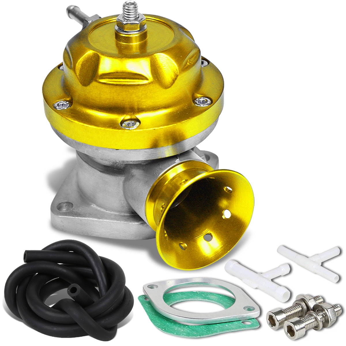
Yep it works as intended so how could I give it anything but 5 stars.I purchased this overpressure safety valve to upgrade my 150 psi system to a 200 psi system because my pump and tank can easily handle it.Allong with a 200 psi pressure shut off switch and hornblasters pressure regulator for the ***** horns. I get much more volume in my 5 gallon tank for my onboard air system making airing up the tires after 4x4ing much quicker.

[{"id":8645059313754,"title":"Default Title","option1":"Default Title","option2":null,"option3":null,"sku":"SV-150A","requires_shipping":true,"taxable":true,"featured_image":null,"available":true,"name":"150 PSI Safety Blow-off Valve (for 90-120 PSI Systems)","public_title":null,"options":["Default Title"],"price":999,"weight":45,"compare_at_price":null,"inventory_quantity":-347,"inventory_management":null,"inventory_policy":"deny","barcode":"817562022780","requires_selling_plan":false,"selling_plan_allocations":[]}]

1/4" MNPT ASME safety valves are manufactured to ASME standards and certified by the national board of boiler and pressure vessel inspectors. Valves are interchangeable with all other ASME valves of same size and pressure. Valve resets after pressure drops by 50%.

1/4" MNPT ASME safety valves are manufactured to ASME standards and certified by the national board of boiler and pressure vessel inspectors. Valves are interchangeable with all other ASME valves of same size and pressure. Valve resets after pressure drops by 50%. Valve has a pop off pressure of 125 PSI.
The liquefaction process must be designed efficiently so that the LNG can be offered economically. The necessary cryogenic media temperatures of -161 to -164 °C represent a challenge for the technical design of the individual components in the plant. This also applies in particular to the safety valves, which must function reliably as the final protection in the event of overpressure, even at the cryogenic process and Russian ambient temperatures.
LESER valves meet all requirements for use in natural gas liquefaction plants and offer a complete product range. The valves are designed in the low-maintenance “Durable Design” and can be adapted to the plants by various options.
The tightness of the safety valves has been proven under real conditions at media temperatures below -146 °C on LESER’s own cryogenic test bench. The precise helium leak test is based on the DIN EN 13648-1 standard.
The plant efficiency was supported by the use of pilot-operated safety valves (POSV) in the relevant areas. In contrast to spring-loaded safety valves, they are tight until they respond and thus meet the requirement of a higher operating pressure in relation to the response pressure of the plant. Six POSVs now support the efficiency of LIMUM® technology the liquefaction plant.
For the LNG low temperature range, LESER has further developed the design modularly so that it can be adapted to the respective project requirements. In the plant in Russia, for example, an evaporator was used and the pilot was thermally decoupled from the main valve to ensure a gaseous media state in the pilot. A temperature-resistant PTFE compound for piston sealing in the main valve enables the spring-loaded lip seal to be used at operating temperatures as low as -162 °C. The main valve is equipped with a PTFE compound for the sealing of the piston. The special seat bushing design does not require a soft seal in the wetted inlet area. The controlling pilot valve is available with a low-temperature resistant soft seal in Pop Action and Modulate Action versions for various requirements.
LESER’s project department supported Linde from the first FEED phase to the commissioning of the project. The production segment “Project Assembly” is specially designed for the requirements of projects and offers optimal conditions for customer acceptance.
An overpressure event refers to any condition which would cause pressure in a vessel or system to increase beyond the specified design pressure or maximum allowable working pressure (MAWP).
Many electronic, pneumatic and hydraulic systems exist today to control fluid system variables, such as pressure, temperature and flow. Each of these systems requires a power source of some type, such as electricity or compressed air in order to operate. A pressure Relief Valve must be capable of operating at all times, especially during a period of power failure when system controls are nonfunctional. The sole source of power for the pressure Relief Valve, therefore, is the process fluid.
Once a condition occurs that causes the pressure in a system or vessel to increase to a dangerous level, the pressure Relief Valve may be the only device remaining to prevent a catastrophic failure. Since reliability is directly related to the complexity of the device, it is important that the design of the pressure Relief Valve be as simple as possible.
The pressure Relief Valve must open at a predetermined set pressure, flow a rated capacity at a specified overpressure, and close when the system pressure has returned to a safe level. Pressure Relief Valves must be designed with materials compatible with many process fluids from simple air and water to the most corrosive media. They must also be designed to operate in a consistently smooth and stable manner on a variety of fluids and fluid phases.
The basic spring loaded pressure Relief Valve has been developed to meet the need for a simple, reliable, system actuated device to provide overpressure protection.
The Valve consists of a Valve inlet or nozzle mounted on the pressurized system, a disc held against the nozzle to prevent flow under normal system operating conditions, a spring to hold the disc closed, and a body/Bonnet to contain the operating elements. The spring load is adjustable to vary the pressure at which the Valve will open.
When a pressure Relief Valve begins to lift, the spring force increases. Thus system pressure must increase if lift is to continue. For this reason pressure Relief Valves are allowed an overpressure allowance to reach full lift. This allowable overpressure is generally 10% for Valves on unfired systems. This margin is relatively small and some means must be provided to assist in the lift effort.
Most pressure Relief Valves, therefore, have a secondary control chamber or huddling chamber to enhance lift. As the disc begins to lift, fluid enters the control chamber exposing a larger area of the disc to system pressure.
This causes an incremental change in force which overcompensates for the increase in spring force and causes the Valve to open at a rapid rate. At the same time, the direction of the fluid flow is reversed and the momentum effect resulting from the change in flow direction further enhances lift. These effects combine to allow the Valve to achieve maximum lift and maximum flow within the allowable overpressure limits. Because of the larger disc area exposed to system pressure after the Valve achieves lift, the Valve will not close until system pressure has been reduced to some level below the set pressure. The design of the control chamber determines where the closing point will occur.
When superimposed back pressure is variable, a balanced bellows or balanced piston design is recommended. A typical balanced bellow is shown on the right. The bellows or piston is designed with an effective pressure area equal to the seat area of the disc. The Bonnet is vented to ensure that the pressure area of the bellows or piston will always be exposed to atmospheric pressure and to provide a telltale sign should the bellows or piston begin to leak. Variations in back pressure, therefore, will have no effect on set pressure. Back pressure may, however, affect flow.
A safety Valve is a pressure Relief Valve actuated by inlet static pressure and characterized by rapid opening or pop action. (It is normally used for steam and air services.)
A low-lift safety Valve is a safety Valve in which the disc lifts automatically such that the actual discharge area is determined by the position of the disc.
A full-lift safety Valve is a safety Valve in which the disc lifts automatically such that the actual discharge area is not determined by the position of the disc.
A Relief Valve is a pressure relief device actuated by inlet static pressure having a gradual lift generally proportional to the increase in pressure over opening pressure. It may be provided with an enclosed spring housing suitable for closed discharge system application and is primarily used for liquid service.
A safety Relief Valve is a pressure Relief Valve characterized by rapid opening or pop action, or by opening in proportion to the increase in pressure over the opening pressure, depending on the application and may be used either for liquid or compressible fluid.
A conventional safety Relief Valve is a pressure Relief Valve which has its spring housing vented to the discharge side of the Valve. The operational characteristics (opening pressure, closing pressure, and relieving capacity) are directly affected by changes of the back pressure on the Valve.
A balanced safety Relief Valve is a pressure Relief Valve which incorporates means of minimizing the effect of back pressure on the operational characteristics (opening pressure, closing pressure, and relieving capacity).
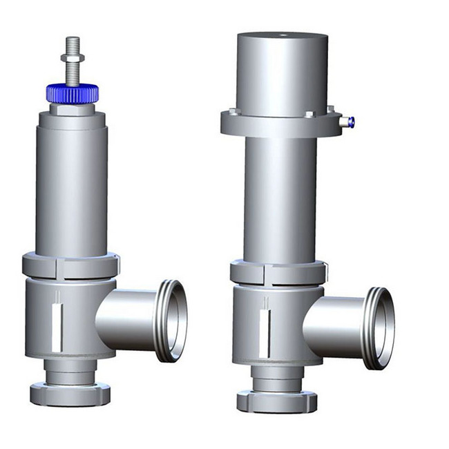
A pilotoperated pressure Relief Valve is a pressure Relief Valve in which the major relieving device is combined with and is controlled by a self-actuated auxiliary pressure Relief Valve.
A poweractuated pressure Relief Valve is a pressure Relief Valve in which the major relieving device is combined with and controlled by a device requiring an external source of energy.
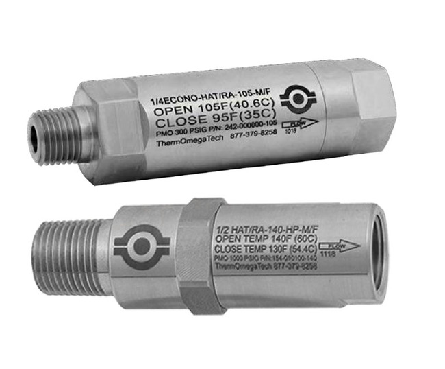
A temperature-actuated pressure Relief Valve is a pressure Relief Valve which may be actuated by external or internal temperature or by pressure on the inlet side.
A vacuum Relief Valve is a pressure relief device designed to admit fluid to prevent an excessive internal vacuum; it is designed to reclose and prevent further flow of fluid after normal conditions have been restored.
Many Codes and Standards are published throughout the world which address the design and application of pressure Relief Valves. The most widely used and recognized of these is the ASME Boiler and Pressure Vessel Code, commonly called the ASME Code.
The ASME Code provides rules for the design and construction of pressure vessels. Various sections of the Code cover fired vessels, nuclear vessels, unfired vessels and additional subjects, such as welding and nondestructive examination. Vessels manufactured in accordance with the ASME Code are required to have overpressure protection. The type and design of allowable overpressure protection devices is spelled out in detail in the Code.
is the gauge pressure at which the lift is sufficient to discharge the predetermined flowing capacity. It is equal to the set pressure plus opening pressure difference.
is the calculated mass flow from an orifice having a cross sectional area equal to the flow area of the safety Valve without regard to flow losses of the Valve.
the pressure at which a Valve is set on a test rig using a test fluid at ambient temperature. This test pressure includes corrections for service conditions e.g. backpressure or high temperatures.
is that portion of the measured relieving capacity permitted by the applicable code or regulation to be used as a basis for the application of a pressure relieving device.
is the value of increasing static inlet pressure of a pressure Relief Valve at which there is a measurable lift, or at which the discharge becomes continuous as determined by seeing, feeling or hearing.
is the maximum allowable working pressure plus the accumulation as established by reference to the applicable codes for operating or fire contingencies.
Because cleanliness is essential to the satisfactory operation and tightness of a safety Valve, precautions should be taken during storage to keep out all foreign materials. Inlet and outlet protectors should remain in place until the Valve is ready to be installed in the system. Take care to keep the Valve inlet absolutely clean. It is recommended that the Valve be stored indoors in the original shipping container away from dirt and other forms of contamination.
Safety Valves must be handled carefully and never subjected to shocks. Rough handling may alter the pressure setting, deform Valve parts and adversely affect seat tightness and Valve performance.
When it is necessary to use a hoist, the chain or sling should be placed around the Valve body and Bonnet in a manner that will insure that the Valve is in a vertical position to facilitate installation.
Many Valves are damaged when first placed in service because of failure to clean the connection properly when installed. Before installation, flange faces or threaded connections on both the Valve inlet and the vessel and/or line on which the Valve is mounted must be thoroughly cleaned of all dirt and foreign material.
Because foreign materials that pass into and through safety Valves can damage the Valve, the systems on which the Valves are tested and finally installed must also be inspected and cleaned. New systems in particular are prone to contain foreign objects that inadvertently get trapped during construction and will destroy the seating surface when the Valve opens. The system should be thoroughly cleaned before the safety Valve is installed.
The gaskets used must be dimensionally correct for the specific flanges. The inside diameters must fully clear the safety Valve inlet and outlet openings so that the gasket does not restrict flow.
For flanged Valves, draw down all connection studs or bolts evenly to avoid possible distortion of the Valve body. For threaded Valves, do not apply a wrench to the Valve body. Use the hex flats provided on the inlet bushing.
Safety Valves are intended to open and close within a narrow pressure range. Valve installations require accurate design both as to inlet and discharge piping. Refer to International, National and Industry Standards for guidelines.
The Valve should be mounted vertically in an upright position either directly on a nozzle from the pressure vessel or on a short connection fitting that provides a direct, unobstructed flow between the vessel and the Valve. Installing a safety Valve in other than this recommended position will adversely affect its operation.
Discharge piping should be simple and direct. A "broken" connection near the Valve outlet is preferred wherever possible. All discharge piping should be run as direct as is practicable to the point of final release for disposal. The Valve must discharge to a safe disposal area. Discharge piping must be drained properly to prevent the accumulation of liquids on the downstream side of the safety Valve.
The weight of the discharge piping should be carried by a separate support and be properly braced to withstand reactive thrust forces when the Valve relieves. The Valve should also be supported to withstand any swaying or system vibrations.
If the Valve is discharging into a pressurized system be sure the Valve is a "balanced" design. Pressure on the discharge of an "unbalanced" design will adversely affect the Valve performance and set pressure.
The Bonnets of balanced bellows safety Valves must always be vented to ensure proper functioning of the Valve and to provide a telltale in the event of a bellows failure. Do not plug these open vents. When the fluid is flammable, toxic or corrosive, the Bonnet vent should be piped to a safe location.
It is important to remember that a pressure Relief Valve is a safety device employed to protect pressure vessels or systems from catastrophic failure. With this in mind, the application of pressure Relief Valves should be assigned only to fully trained personnel and be in strict compliance with rules provided by the governing codes and standards.

Pressure relief valves (safety relief valves) are designed to open at a preset pressure and discharge fluid until pressure drops to acceptable levels. The development of the safety relief valve has an interesting history.
Denis Papin is credited by many sources as the originator of the first pressure relief valve (circa 1679) to prevent overpressure of his steam powered “digester”. His pressure relief design consisted of a weight suspended on a lever arm. When the force of the steam pressure acting on the valve exceeded the force of the weight acting through the lever arm the valve opened. Designs requiring a higher relief pressure setting required a longer lever arm and/or larger weights. This simple system worked however more space was needed and it coud be easily tampered with leading to a possible overpressure and explosion. Another disadvantage was premature opening of the valve if the device was subjected to bouncing movement.
Direct-acting deadweight pressure relief valves: Later to avoid the disadvantages of the lever arrangement, direct-acting deadweight pressure relief valves were installed on early steam locomotives. In this design, weights were applied directly to the top of the valve mechanism. To keep the size of the weights in a reasonable range, the valve size was often undersized resulting in a smaller vent opening than required. Often an explosion would occur as the steam pressure rose faster than the vent could release excess pressure. Bouncing movements also prematurely released pressure.
Direct acting spring valves: Timothy Hackworth is believed to be the first to use direct acting spring valves (circa 1828) on his locomotive engine called the Royal George. Timothy utilized an accordion arrangement of leaf springs, which would later be replaced with coil springs, to apply force to the valve. The spring force could be fine tuned by adjusting the nuts retaining the leaf springs.
Refinements to the direct acting spring relief valve design continued in subsequent years in response to the widespread use of steam boilers to provide heat and to power locomotives, river boats, and pumps. Steam boilers are less common today but the safety relief valve continues to be a critical component, in systems with pressure vessels, to protect against damage or catastrophic failure.
Each application has its own unique requirements but before we get into the selection process, let’s have a look at the operating principles of a typical direct acting pressure relief valve.
In operation, the pressure relief valve remains normally closed until pressures upstream reaches the desired set pressure. The valve will crack open when the set pressure is reached, and continue to open further, allowing more flow as over pressure increases. When upstream pressure falls a few psi below the set pressure, the valve will close again.
Most commonly, pressure relief valves employ a spring loaded “poppet” valve as a valve element. The poppet includes an elastomeric seal or, in some high pressure designs a thermoplastic seal, which is configured to make a seal on a valve seat. In operation, the spring and upstream pressure apply opposing forces on the valve. When the force of the upstream pressure exerts a greater force than the spring force, then the poppet moves away from the valve seat which allows fluid to pass through the outlet port. As the upstream pressure drops below the set point the valve then closes.
Piston style designs are often used when higher relief pressures are required, when ruggedness is a concern or when the relief pressure does not have to be held to a tight tolerance. Piston designs tend to be more sluggish, compared to diaphragm designs due to friction from the piston seal. In low pressure applications, or when high accuracy is required, the diaphragm style is preferred. Diaphragm relief valves employ a thin disc shaped element which is used to sense pressure changes. They are usually made of an elastomer, however, thin convoluted metal is used in special applications. Diaphragms essentially eliminate the friction inherent with piston style designs. Additionally, for a particular relief valve size, it is often possible to provide a greater sensing area with a diaphragm design than would be feasible with a piston style design.
The reference force element is usually a mechanical spring. This spring exerts a force on the sensing element and acts to close the valve. Many pressure relief valves are designed with an adjustment which allows the user to adjust the relief pressure set-point by changing the force exerted by the reference spring.
The chemical properties of the fluid should be considered before determining the best materials for your application. Each fluid will have its own unique characteristics so care must be taken to select the appropriate body and seal materials that will come in contact with the fluid. The parts of the pressure relief valve in contact with the fluid are known as the “wetted” components. If the fluid is flammable or hazardous in nature the pressure relief valve must be capable of discharging it safely.
In many high technology applications space is limited and weight is a factor. Some manufactures specialize in miniature components and should be consulted. Material selection, particularly the relief valve body components, will impact weight. Also carefully consider the port (thread) sizes, adjustment styles, and mounting options as these will influence size and weight.
In many high technology applications space is limited and weight is a factor. Some manufactures specialize in miniature components and should be consulted. Material selection, particularly the relief valve body components, will impact weight. Also carefully consider the port (thread) sizes, adjustment styles, and mounting options as these will influence size and weight.
A wide range of materials are available to handle various fluids and operating environments. Common pressure relief valve component materials include brass, plastic, and aluminum. Various grades of stainless steel (such as 303, 304, and 316) are available too. Springs used inside the relief valve are typically made of music wire (carbon steel) or stainless steel.
Equally important is the compatibility of the seal material with the fluid and with the operating temperature range. Buna-N is a typical seal material. Optional seals are offered by some manufacturers and these include: Fluorocarbon, EPDM, Silicone, and Perfluoroelastomer.
The materials selected for the pressure relief valve not only need to be compatible with the fluid but also must be able to function properly at the expected operating temperature. The primary concern is whether or not the elastomer chosen will function properly throughout the expected temperature range. Additionally, the operating temperature may affect flow capacity and/or the spring rate in extreme applications.
Beswick Engineering manufactures four styles of pressure relief valves to best suit your application. The RVD and RVD8 are diaphragm based pressure relief valves which are suited to lower relief pressures. The RV2 and BPR valves are piston based designs.

... -start valve with Series MX2 air treatment units without the need for additional connection interfaces. The soft-start valve is positioned upstream of the safety valves, ...
Two hands safety valve, which allows a safety use of two hands pneumatic controls (for example two push-button 3/2 N.C. to a certain distance) excluding false signals in case of push-button ...
The SI2 safety valve prevents the allowed operating pressure from being exceeded by more than 10%. If, after opening, the adjusted response pressure falls ...
... stainless steel full-lift clean service safety valve designed to AD Merkblatt A2 and TRD 421 standards and suitable for pure steam, vapour and inert gases.
Insert style flow control valves are comprised of a precision orifice in parallel with a check valve, combined into a single component. Each is designed for easy installation into metal housings using ...
Press-in style flow control valves are comprised of a precision flow orifice in parallel with a check valve, combined into a single component. Each part is designed for easy installation into plastic ...
If you have been searching for a safety release valve that you can use to reduce short-term pressure surges successfully and diminish the effects of gas leaks, this is the product for you. With a pe of ...
... have been type tested as well. These pressure regulators have safety valves which will slam shut in the event of emergencies, such as the gas reaching too high a pressure level. The valve ...
This product has hydraulically actuated class A gas safety valves to EN 161 used for automatic shut-off. It shuts off when unstimulated for gas and air, or even biologically produced methane. It has AISi ...
The S 104 Safety Shut Off valve is mainly used to avoid any damage to components as well as to avoid too high or too low pressure in the gas train. This could cause high financial losses and/or injured ...
The S50 Safety Shut Off valve is mainly used to avoid any damage to components as well as to avoid too high or too low pressure in the gas train. This could cause high financial losses and/or injured ...
The S100 Safety Shut Off valve is mainly used to avoid any damage to components as well as to avoid too high or too low pressure in the gas train. This could cause high financial losses and/or injured ...
... Pressure Safety Valve + Rupture Disk is protected and may be utilized autonomously as essential security gadgets or in conjunction. There are 3 possible combinations. The first combinations ...
Excavator pipe-rupture valves prevent uncontrolled cylinder movement in the event that a pipe or hose bursts. The ESV valve fulfills all of the requirements of the ISO 8643 and EN 474-5 standards for ...
Material: Body- CF8M; Valve Seat- CF8M Métal Seat, PTFE Soft Seat available Orifice Size: fc"(15mm), 3/4M(20mm), l"(25mm), l1/4,’(32mm)I ltë”(40mm), ...
The Safety valves from ATOS are designed to guarantee protection for application on various devices, especially those that monitor spool position. They are also recommended for hydraulic ...

Alibaba.com offers 60 high pressure blow off valve products. About 41% % of these are valves, 16%% are other engine parts, and 15%% are intake & exhaust valves & valve tappets.
Level and Flow Control Engineers manufacturing and EXPORTING Pressure Relief Valve, Pressure Safety Valve under the brand name of BEEKAY.Pressure Relief Valve can control the overpressure in the tanks, vessels, pipelines, pumps and other capital equipments. All our pressure relief valves are spring loaded - right angled type
Level and Flow Control Engineers manufacturing, supplying, exporting Pressure Relief Valve, Relief Valve, safety valves under the brand name of BEEKAY - Made in INDIA.Beekay is well know in the industry for Quality, timely delivery. Reflief Valves are used with high Quality Springs to maintain set pressure and Re-Set Pressures.
Beekay brand Safety Relief Valve, Pressure Relief Valve, Relief Valve are manufactured by Level and Flow Control Engineers in INDIA.Valves are more accuracy - Valve Open and Valve Close are perfect related to 10% Over pressure as a Set pressure and 10% Less pressure as a Re-Set Pressure. We are expecting enquiry and orders from all over the world mainly from UAE, Middle East, Thailand, Indonesia, Philipines, Srilanka, Pakistant, Maldivies, Malaysia, Singapore.
LFCE manufacturing and Exporting Pressure Relief Valves.Our brand name isBEEKAY. Relief Valves are used to release the Excess Pressure in the Tanks, Vessels, Pipelines, Water Heads. PRV - Set Pressure and Re-Set Pressures are very accurate having accumulation and blow down having Range between 2% to 10%
LFCE Manufacturing, Supplying, Exporting Big Size Safety Valves, Safety Relief Valves, Pressure Relief Valves for Low and Medium Pressures. Mainly it will be used in the Deareators, Low Pressure big pipelines, Hydrocarbon Projects, Feedwaters, CondensatesPressure Range 0 to 25 barour Brand Beekay is well establised in the global marketExpecting enquiry and orders from all over the globe.
Beekay brand Pressure Safety Valves are manufactured by Level and Flow Control Engineers at INDIA. We also manufacturing Safety Valve, Safety Relief Valve, Ball Float Valves, Needle Valves, Foot Valves. For timely delivery and fine quality any one can place order on us. We have very good infrastructure to export the products all over the world including Australlia, Europe, UAE, Middle East, South Asian Countries.
LFCE manufacturing and Exporting WATER PRESSURE RELIEF VALVESunder the brand name ofBEEKAY.It is high quality and low price having materials of Bronze, Brass, CS, SS Grades. Water Pressure Relief Valves can control the pressure in the pipelines and capital equipments.We are expecting good enquiry and orders from all over the world


 8613371530291