
blowdown pressure of safety valve in stock

Blowdown Valves keep boilers clean. Blowdown valves are used to vent the impurities, sediment, and other solids that are present in boiler water. They are opened periodically to prevent buildup. They are also used to regulate the conductivity of the water in a boiler, because higher electrical conductivity causes scale to build up faster.
Blowdown valves come in two varieties, fast-open and slow-open. Fast-open valves act as the quick cutoff, while slow-open valves allow modulation of the water flow.
During a blowdown, the fast-open valve is opened first. This feeds the slow-open valve, which can then be opened gradually for operator safety and to prevent thermal shock to the drain pipes.
There are four locations where blowdown valves are typically installed:The bottom of the sight glassto keep water readings accurateThe bottom of the boilerto remove heavier solids, sediment, and impuritiesLevel with the surface of the water inside the boilerto allow floating impurities to be blown outThe low water cutoff, to confirm that it is operating properly
Without the blowdown valve in place, sediment and other impurities would gradually build up along the inside surface of the boiler. This would not only reduce the boiler’s operating efficiency, it could also become a safety hazard by creating uneven heating and metal stress.
Blowdown valves also regulate electrical conductivity in the boiler water by regulating the amount of suspended solids. Higher electrical conductivity creates faster scale buildup, which reduces a boiler’s operating efficiency. Higher conductivity also decreases the life of the boiler by accelerating the corrosive effects of the oxygen inside.
Things to Consider about Blowdown Valves:When the blowdown valve is opened, the water is extremely hot, and has a lot of steam pressure behind it. Always use extreme caution and be aware of your environment when operating a blowdown valve.Always wear proper protective equipment when operating a blowdown valve.Open the valve slowly. This is not only for operator safety, it also reduces thermal shock to the venting pipes.After completing a blowdown, momentarily crack the slow-open valve to release the pressure between the valves.

Blowdown isthe % difference between Closing Pressure (Reseating Pressure) and Set Pressure. In general, Blowdown is set to 7% for ASME Section VIII and 4-6% for ASME Section I. If the blowdown is too much, PRV Will close slowly and cause a lot of Process Fluid loss. If the Blowdown is too low, PRV will cause a lot of Simmer, which causes Disc and Seat ‘s Valve can damage.
For Pressure Relief Valve (PRV) is designed in accordance with ASME Section I Power Boiler has to be Overpressure or % of the pressure that exceeds the Set Pressure of the PRV openno more than 6%and will be 6%as well
In addition, forBlowdown (%difference betweenReseating Pressureand Set Pressure), there must be at least 2% Minimum Blowdown of Set Pressure or 15 kPa in the case of Set Pressure below 750 kPa to prevent chattering between Seat and Discof the PRV and the maximum blowdown must not exceed the values in the table divided by the set pressure of the PRV .

As soon as mankind was able to boil water to create steam, the necessity of the safety device became evident. As long as 2000 years ago, the Chinese were using cauldrons with hinged lids to allow (relatively) safer production of steam. At the beginning of the 14th century, chemists used conical plugs and later, compressed springs to act as safety devices on pressurised vessels.
Early in the 19th century, boiler explosions on ships and locomotives frequently resulted from faulty safety devices, which led to the development of the first safety relief valves.
In 1848, Charles Retchie invented the accumulation chamber, which increases the compression surface within the safety valve allowing it to open rapidly within a narrow overpressure margin.
Today, most steam users are compelled by local health and safety regulations to ensure that their plant and processes incorporate safety devices and precautions, which ensure that dangerous conditions are prevented.
The principle type of device used to prevent overpressure in plant is the safety or safety relief valve. The safety valve operates by releasing a volume of fluid from within the plant when a predetermined maximum pressure is reached, thereby reducing the excess pressure in a safe manner. As the safety valve may be the only remaining device to prevent catastrophic failure under overpressure conditions, it is important that any such device is capable of operating at all times and under all possible conditions.
Safety valves should be installed wherever the maximum allowable working pressure (MAWP) of a system or pressure-containing vessel is likely to be exceeded. In steam systems, safety valves are typically used for boiler overpressure protection and other applications such as downstream of pressure reducing controls. Although their primary role is for safety, safety valves are also used in process operations to prevent product damage due to excess pressure. Pressure excess can be generated in a number of different situations, including:
The terms ‘safety valve’ and ‘safety relief valve’ are generic terms to describe many varieties of pressure relief devices that are designed to prevent excessive internal fluid pressure build-up. A wide range of different valves is available for many different applications and performance criteria.
In most national standards, specific definitions are given for the terms associated with safety and safety relief valves. There are several notable differences between the terminology used in the USA and Europe. One of the most important differences is that a valve referred to as a ‘safety valve’ in Europe is referred to as a ‘safety relief valve’ or ‘pressure relief valve’ in the USA. In addition, the term ‘safety valve’ in the USA generally refers specifically to the full-lift type of safety valve used in Europe.
Pressure relief valve- A spring-loaded pressure relief valve which is designed to open to relieve excess pressure and to reclose and prevent the further flow of fluid after normal conditions have been restored. It is characterised by a rapid-opening ‘pop’ action or by opening in a manner generally proportional to the increase in pressure over the opening pressure. It may be used for either compressible or incompressible fluids, depending on design, adjustment, or application.
Safety valves are primarily used with compressible gases and in particular for steam and air services. However, they can also be used for process type applications where they may be needed to protect the plant or to prevent spoilage of the product being processed.
Relief valve - A pressure relief device actuated by inlet static pressure having a gradual lift generally proportional to the increase in pressure over opening pressure.
Relief valves are commonly used in liquid systems, especially for lower capacities and thermal expansion duty. They can also be used on pumped systems as pressure overspill devices.
Safety relief valve - A pressure relief valve characterised by rapid opening or pop action, or by opening in proportion to the increase in pressure over the opening pressure, depending on the application, and which may be used either for liquid or compressible fluid.
In general, the safety relief valve will perform as a safety valve when used in a compressible gas system, but it will open in proportion to the overpressure when used in liquid systems, as would a relief valve.
Safety valve- A valve which automatically, without the assistance of any energy other than that of the fluid concerned, discharges a quantity of the fluid so as to prevent a predetermined safe pressure being exceeded, and which is designed to re-close and prevent further flow of fluid after normal pressure conditions of service have been restored.

In order to ensure that the maximum allowable accumulation pressure of any system or apparatus protected by a safety valve is never exceeded, careful consideration of the safety valve’s position in the system has to be made. As there is such a wide range of applications, there is no absolute rule as to where the valve should be positioned and therefore, every application needs to be treated separately.
A common steam application for a safety valve is to protect process equipment supplied from a pressure reducing station. Two possible arrangements are shown in Figure 9.3.3.
The safety valve can be fitted within the pressure reducing station itself, that is, before the downstream stop valve, as in Figure 9.3.3 (a), or further downstream, nearer the apparatus as in Figure 9.3.3 (b). Fitting the safety valve before the downstream stop valve has the following advantages:
• The safety valve can be tested in-line by shutting down the downstream stop valve without the chance of downstream apparatus being over pressurised, should the safety valve fail under test.
• When setting the PRV under no-load conditions, the operation of the safety valve can be observed, as this condition is most likely to cause ‘simmer’. If this should occur, the PRV pressure can be adjusted to below the safety valve reseat pressure.
• Any additional take-offs downstream are inherently protected. Only apparatus with a lower MAWP requires additional protection. This can have significant cost benefits.
Indeed, a separate safety valve may have to be fitted on the inlet to each downstream piece of apparatus, when the PRV supplies several such pieces of apparatus.
• If supplying one piece of apparatus, which has a MAWP pressure less than the PRV supply pressure, the apparatus must be fitted with a safety valve, preferably close-coupled to its steam inlet connection.
• If a PRV is supplying more than one apparatus and the MAWP of any item is less than the PRV supply pressure, either the PRV station must be fitted with a safety valve set at the lowest possible MAWP of the connected apparatus, or each item of affected apparatus must be fitted with a safety valve.
• The safety valve must be located so that the pressure cannot accumulate in the apparatus viaanother route, for example, from a separate steam line or a bypass line.
It could be argued that every installation deserves special consideration when it comes to safety, but the following applications and situations are a little unusual and worth considering:
• Fire - Any pressure vessel should be protected from overpressure in the event of fire. Although a safety valve mounted for operational protection may also offer protection under fire conditions,such cases require special consideration, which is beyond the scope of this text.
• Exothermic applications - These must be fitted with a safety valve close-coupled to the apparatus steam inlet or the body direct. No alternative applies.
• Safety valves used as warning devices - Sometimes, safety valves are fitted to systems as warning devices. They are not required to relieve fault loads but to warn of pressures increasing above normal working pressures for operational reasons only. In these instances, safety valves are set at the warning pressure and only need to be of minimum size. If there is any danger of systems fitted with such a safety valve exceeding their maximum allowable working pressure, they must be protected by additional safety valves in the usual way.
In order to illustrate the importance of the positioning of a safety valve, consider an automatic pump trap (see Block 14) used to remove condensate from a heating vessel. The automatic pump trap (APT), incorporates a mechanical type pump, which uses the motive force of steam to pump the condensate through the return system. The position of the safety valve will depend on the MAWP of the APT and its required motive inlet pressure.
This arrangement is suitable if the pump-trap motive pressure is less than 1.6 bar g (safety valve set pressure of 2 bar g less 0.3 bar blowdown and a 0.1 bar shut-off margin). Since the MAWP of both the APT and the vessel are greater than the safety valve set pressure, a single safety valve would provide suitable protection for the system.
However, if the pump-trap motive pressure had to be greater than 1.6 bar g, the APT supply would have to be taken from the high pressure side of the PRV, and reduced to a more appropriate pressure, but still less than the 4.5 bar g MAWP of the APT. The arrangement shown in Figure 9.3.5 would be suitable in this situation.
Here, two separate PRV stations are used each with its own safety valve. If the APT internals failed and steam at 4 bar g passed through the APT and into the vessel, safety valve ‘A’ would relieve this pressure and protect the vessel. Safety valve ‘B’ would not lift as the pressure in the APT is still acceptable and below its set pressure.
It should be noted that safety valve ‘A’ is positioned on the downstream side of the temperature control valve; this is done for both safety and operational reasons:
Operation - There is less chance of safety valve ‘A’ simmering during operation in this position,as the pressure is typically lower after the control valve than before it.
Also, note that if the MAWP of the pump-trap were greater than the pressure upstream of PRV ‘A’, it would be permissible to omit safety valve ‘B’ from the system, but safety valve ‘A’ must be sized to take into account the total fault flow through PRV ‘B’ as well as through PRV ‘A’.
A pharmaceutical factory has twelve jacketed pans on the same production floor, all rated with the same MAWP. Where would the safety valve be positioned?
One solution would be to install a safety valve on the inlet to each pan (Figure 9.3.6). In this instance, each safety valve would have to be sized to pass the entire load, in case the PRV failed open whilst the other eleven pans were shut down.
If additional apparatus with a lower MAWP than the pans (for example, a shell and tube heat exchanger) were to be included in the system, it would be necessary to fit an additional safety valve. This safety valve would be set to an appropriate lower set pressure and sized to pass the fault flow through the temperature control valve (see Figure 9.3.8).

Providing you the best range of stainless steel water pressure relief valves, safety and pressure relief valves, flanged safety relief valve, industrial safety relief valves, pressure safety relief valves and cast steel safety relief valves with effective & timely delivery.

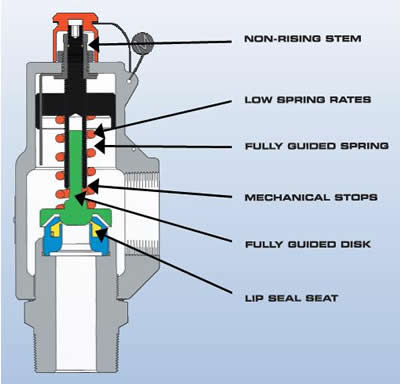
The Consolidated 19000 Series valve provides quality performance in seat tightness, capacity, and blowdown on most media. It surpasses ASME code requirements and is CE compliant to European PED specifications in functional performance and overpressure protection.
The Type 19000 safety relief valve is suitable for overpressure protection in chemical, petrochemical, refinery, power generation (nuclear and commercial), and other commercial applications.

(a) Safety relief valves shall be so constructed that no shocks detrimental to the valve or pressure vessel are produced when lifting or closing. Safety relief valves shall be designed to open sharply and reach full lift and capacity at the maximum accumulation. Valve closure after popping shall be clean and sharp. Safety relief valves shall operate satisfactorily without wiredrawing and chattering at any stage of operation.
(b) Safety relief valves having adjustable blow-down construction shall be adjusted to close after blowing down not more than 5 percent of the set pressure. Valves shall be adjusted to pop within a tolerance of plus or minus 3 percent of the set pressure, except that for pressures of 70 p.s.i. and below, the tolerance in popping pressure shall not vary more than plus or minus 2 p.s.i.
%20Cross-Section.png)
When you’re in the market for a pressure relief valve, a sales rep has probably asked you “what set pressure do you need?” This piece of information isrequiredto purchase a new pressure relief valve. You might have been able to retrieve this info from an old valve nameplate or look it up in your computer system, but what does the value mean?
Set pressure is the point at which a pressure relief valve is set to open under service conditions.It’s measured in pounds per square inch gauge (PSIG).
Set pressure sounds simple, right? Not always — there are rules and recommendations you should keep in mind when you’re determining the set pressure for pressure relief valves.
Identifying the process media, or service, of a valve is important to set pressure. If a valve has the correct set pressure but is used on the wrong application, there’s a chance the valve wouldn’t open when needed. This could cause the system or vessel to overpressure.
When the pressure in a system or vessel increases to a dangerous level, the pressure relief valve is there as the last line of defense. The valve opens when the inlet pressure exceeds the set pressure. When vessel pressure slightly exceeds the set pressure, fluid moves past the seating surface into the huddling chamber. The controlled pressure built up inside the huddling chamber will then overcome the spring force, causing the disc to lift and the valve to pop open.
After the valve opens, it will only close once the pressure has dropped a certain percentage below the set pressure. This percentage is referred to as blowdown, and will typically range anywhere from 4% to 10% depending on the applicable code.
Determining set pressure is just one thing you need to determine when you’re specifying a pressure relief or safety valve. If you need assistance finding the right-fit valve, contact us at (314) 665-1741.
The pressure below the valve must increase above the set pressure before the safety valve reaches a noticeable lift. As a result of the restriction of flow between the disc and the adjusting ring, pressure builds up in the huddling chamber. The pressure now acts on an enlarged disc area. This increases the force Fp so that the additional spring force required to further compress the spring is overcome. The valve will open rapidly with a "pop", in most cases to its full lift.
Overpressure is the pressure increase above the set pressure necessary for the pressure relief valve to achieve full lift and capacity. The overpressure is usually expressed as a percentage of the set pressure. Codes and standards provide limits for the maximum overpressure. A typical value is 10%, ranging between 3% and 21% depending on the code and application.
In most applications a properly sized pressure relief valve will decrease the pressure in the vessel when discharging. The pressure in the vessel will decrease at any subsequent point, but not later than the end of the upset situation. A decreasing pressure in the vessel will lower the force Fp. At set pressure however the flow is still acting on the enlarged disc area, which will keep the valve open. A further reduction in pressure is required until the spring force Fs is again greater than Fp and the pressure relief valve begins to reclose. At the reseating pressure the disc will touch the nozzle again and the pressure relief valve recloses.
Blowdown is the difference between set pressure and reseating pressure of a pressure relief valve expressed as a percentage of set pressure. Typical blowdown values as defined in codes and standards are -7% and -10%, ranging from -4% to -20% depending on the code and service (steam, gas or liquid).
Safety Relief ValvePioneers in the industry, we offer safety relief valve, pressure safety valve, thermal relief valve, sanitary safety valve, flange end safety relief valve and high pressure relief valve from India.


 8613371530291