
blowdown pressure of safety valve free sample

In order to ensure that the maximum allowable accumulation pressure of any system or apparatus protected by a safety valve is never exceeded, careful consideration of the safety valve’s position in the system has to be made. As there is such a wide range of applications, there is no absolute rule as to where the valve should be positioned and therefore, every application needs to be treated separately.
A common steam application for a safety valve is to protect process equipment supplied from a pressure reducing station. Two possible arrangements are shown in Figure 9.3.3.
The safety valve can be fitted within the pressure reducing station itself, that is, before the downstream stop valve, as in Figure 9.3.3 (a), or further downstream, nearer the apparatus as in Figure 9.3.3 (b). Fitting the safety valve before the downstream stop valve has the following advantages:
• The safety valve can be tested in-line by shutting down the downstream stop valve without the chance of downstream apparatus being over pressurised, should the safety valve fail under test.
• When setting the PRV under no-load conditions, the operation of the safety valve can be observed, as this condition is most likely to cause ‘simmer’. If this should occur, the PRV pressure can be adjusted to below the safety valve reseat pressure.
• Any additional take-offs downstream are inherently protected. Only apparatus with a lower MAWP requires additional protection. This can have significant cost benefits.
Indeed, a separate safety valve may have to be fitted on the inlet to each downstream piece of apparatus, when the PRV supplies several such pieces of apparatus.
• If supplying one piece of apparatus, which has a MAWP pressure less than the PRV supply pressure, the apparatus must be fitted with a safety valve, preferably close-coupled to its steam inlet connection.
• If a PRV is supplying more than one apparatus and the MAWP of any item is less than the PRV supply pressure, either the PRV station must be fitted with a safety valve set at the lowest possible MAWP of the connected apparatus, or each item of affected apparatus must be fitted with a safety valve.
• The safety valve must be located so that the pressure cannot accumulate in the apparatus viaanother route, for example, from a separate steam line or a bypass line.
It could be argued that every installation deserves special consideration when it comes to safety, but the following applications and situations are a little unusual and worth considering:
• Fire - Any pressure vessel should be protected from overpressure in the event of fire. Although a safety valve mounted for operational protection may also offer protection under fire conditions,such cases require special consideration, which is beyond the scope of this text.
• Exothermic applications - These must be fitted with a safety valve close-coupled to the apparatus steam inlet or the body direct. No alternative applies.
• Safety valves used as warning devices - Sometimes, safety valves are fitted to systems as warning devices. They are not required to relieve fault loads but to warn of pressures increasing above normal working pressures for operational reasons only. In these instances, safety valves are set at the warning pressure and only need to be of minimum size. If there is any danger of systems fitted with such a safety valve exceeding their maximum allowable working pressure, they must be protected by additional safety valves in the usual way.
In order to illustrate the importance of the positioning of a safety valve, consider an automatic pump trap (see Block 14) used to remove condensate from a heating vessel. The automatic pump trap (APT), incorporates a mechanical type pump, which uses the motive force of steam to pump the condensate through the return system. The position of the safety valve will depend on the MAWP of the APT and its required motive inlet pressure.
This arrangement is suitable if the pump-trap motive pressure is less than 1.6 bar g (safety valve set pressure of 2 bar g less 0.3 bar blowdown and a 0.1 bar shut-off margin). Since the MAWP of both the APT and the vessel are greater than the safety valve set pressure, a single safety valve would provide suitable protection for the system.
However, if the pump-trap motive pressure had to be greater than 1.6 bar g, the APT supply would have to be taken from the high pressure side of the PRV, and reduced to a more appropriate pressure, but still less than the 4.5 bar g MAWP of the APT. The arrangement shown in Figure 9.3.5 would be suitable in this situation.
Here, two separate PRV stations are used each with its own safety valve. If the APT internals failed and steam at 4 bar g passed through the APT and into the vessel, safety valve ‘A’ would relieve this pressure and protect the vessel. Safety valve ‘B’ would not lift as the pressure in the APT is still acceptable and below its set pressure.
It should be noted that safety valve ‘A’ is positioned on the downstream side of the temperature control valve; this is done for both safety and operational reasons:
Operation - There is less chance of safety valve ‘A’ simmering during operation in this position,as the pressure is typically lower after the control valve than before it.
Also, note that if the MAWP of the pump-trap were greater than the pressure upstream of PRV ‘A’, it would be permissible to omit safety valve ‘B’ from the system, but safety valve ‘A’ must be sized to take into account the total fault flow through PRV ‘B’ as well as through PRV ‘A’.
A pharmaceutical factory has twelve jacketed pans on the same production floor, all rated with the same MAWP. Where would the safety valve be positioned?
One solution would be to install a safety valve on the inlet to each pan (Figure 9.3.6). In this instance, each safety valve would have to be sized to pass the entire load, in case the PRV failed open whilst the other eleven pans were shut down.
If additional apparatus with a lower MAWP than the pans (for example, a shell and tube heat exchanger) were to be included in the system, it would be necessary to fit an additional safety valve. This safety valve would be set to an appropriate lower set pressure and sized to pass the fault flow through the temperature control valve (see Figure 9.3.8).
(a) The inlet opening shall have an inside diameter approximately equal to, or greater than, the seat diameter. In no case shall the maximum opening through any part of the valve be less than ¼ in. (6 mm) in diameter or its equivalent area.
(c) O-rings or other packing devices when used on the stems of safety relief valves shall be so arranged as not to affect their operation or capacity.
(d) The design shall incorporate guiding arrangements necessary to insure consistent operation and tightness. Excessive lengths of guiding surfaces should be avoided. Bottom guided designs are not permitted on safety relief valves.
(f) Safety valves shall be spring loaded. The spring shall be designed so that the full lift spring compression shall be no greater than 80% of the nominal solid deflection. The permanent set of the spring (defined as the difference between the free height and height measured 10 min after the spring has been compressed solid three additional times after presetting at room temperature) shall not exceed 0.5% of the free height.
(g) There shall be a lifting device and a mechanical connection between the lifting device and the disk capable of lifting the disk from the seat a distance of at least 1/16 in. (1.5 mm) with no pressure on the boiler.
(h) A body drain below seat level shall be provided by the Manufacturer for all safety valves and safety relief valves, except that the body drain may be omitted when the valve seat is above the bottom of the inside diameter of the discharge piping. For valves exceeding NPS 2½ (DN 65) the drain hole or holes shall be tapped not less than NPS 3/8 (DN 10). For valves NPS 2½ (DN 65) or smaller, the drain hole shall not be less than ¼ in. (6 mm) in diameter. Body drain connections shall not be plugged during or after field installation. In safety relief valves of the diaphragm type, the space above the diaphragm shall be vented to prevent a buildup of pressure above the diaphragm. Safety relief valves of the diaphragm type shall be so designed that failure or deterioration of the diaphragm material will not impair the ability of the valve to relieve at the rated capacity.
(k) The set pressure tolerances, plus or minus, of safety valves shall not exceed 2 psi (15 kPa), and for safety relief valves shall not exceed 3 psi (20 kPa) for pressures up to and including 60 psig (400 kPa) and 5% for pressures above 60 psig (400 kPa).
(l) Safety valves shall be arranged so that they cannot be reset to relieve at a higher pressure than the maximum allowable working pressure of the boiler.
(e) Material for valve bodies and bonnets or their corresponding metallic pressure containing parts shall be listed in Section II,except that in cases where a manufacturer desires to make use of materials other than those listed in Section II, he shall establish and maintain specifications requiring equivalent control of chemical and physical properties and quality.
(g) No materials liable to fail due to deterioration or vulcanization when subjected to saturated steam temperature corresponding to capacity test pressure shall be used.
(a) A Manufacturer shall demonstrate to the satisfaction of an ASME designee that his manufacturing, production, and testing facilities and quality control procedures will insure close agreement between the performance of random production samples and the performance of those valves submitted for capacity certification.
(c) A Manufacturer may be granted permission to apply, the HV Code Symbol to production pressure relief valves capacity certified in accordance with HG-402.3 provided the following tests are successfully completed. This permission shall expire on the sixth anniversary of the date it is initially granted. The permission may be extended for 6 year periods if the following tests are successfully repeated within the 6 month period before expiration.
(1) Two sample production pressure relief valves of a size and capacity within the capability of an ASME accepted laboratory shall be selected by an ASME designee.
(2) Operational and capacity tests shall be conducted in the presence of an ASME designee at an ASME accepted laboratory. The valve Manufacturer shall be notified of the time of the test and may have representatives present to witness the test.
(3) Should any valve fail to relieve at or above its certified capacity or should it fail to meet performance requirements of this Section, the test shall be repeated at the rate of two replacement valves, selected in accordance with HG-401.3(c)(1), for each valve that failed.
(4) Failure of any of the replacement valves to meet the capacity or the performance requirements of this Section shall be cause for revocation within 60 days of the authorization to use the Code Symbol on that particular type of valve. During this period, the Manufacturer shall demonstrate the cause of such deficiency and the action taken to guard against future occurrence, and the requirements of HG-401.3(c) above shall apply.
(d) Safety valves shall be sealed in a manner to prevent the valve from being taken apart without breaking the seal. Safety relief valves shall be set and sealed so that they cannot be reset without breaking the seal.
(a) Every safety valve shall be tested to demonstrate its popping point, blowdown, and tightness. Every safety relief valve shall be tested to demonstrate its opening point and tightness. Safety valves shall be tested on steam or air and safety relief valves on water, steam, or air. When the blowdown is nonadjustable, the blowdown test may be performed on a sampling basis.
(c) Testing time on safety valves shall be sufficient, depending on size and design, to insure that test results are repeatable and representative of field performance.
HG-401.5 Design Requirements. At the time of the submission of valves for capacity certification, or testing in accordance with this Section, the ASME Designee has the authority to review the design for conformity with the requirements of this Section, and to reject or require modification of designs that do not conform, prior to capacity testing.
HG-402.1 Valve Markings. Each safety or safety-relief valve shall be plainly marked with the required data by the Manufacturer in such a way that the markings will not be obliterated in service. The markings shall be stamped, etched, impressed, or cast on the valve or on a nameplate, which shall be securely fastened to the valve.
(6) year built or, alternatively, a coding may be marked on the valves such that the valve Manufacturer can identify the year the valve was assembled and tested, and
HG-402.2 Authorization to Use ASME Stamp.Each safety valve to which the Code Symbol (Fig. HG-402) is to be applied shall be produced by a Manufacturer and/or Assembler who is in possession of a valid Certificate of Authorization. (See HG-540.) For all valves to be stamped with the HV Symbol, a Certified Individual (CI) shall provide oversight to ensure that the use of the “HV" Code symbol on a safety valve or safety relief valve is in accordance with this Section and that the use of the “HV" Code symbol is documented on a Certificate of Conformance Form, HV-1.
(3) have a record, maintained and certified by the Manufacturer, containing objective evidence of the qualifications of the CI and the training program provided
(1) verify that each item to which the Code Symbol is applied meets all applicable requirements of this Section and has a current capacity certification for the “HV" symbol
(1) The Certificate of Conformance shall be filled out by the Manufacturer and signed by the Certified Individual. Multiple duplicate pressure relief devices may be recorded on a single entry provided the devices are identical and produced in the same lot.
(2) The Manufacturer"s written quality control program shall include requirements for completion of Certificates of Conformance forms and retention by the Manufacturer for a minimum of 5 years.
HG-402.3 Determination of Capacity to Be Stamped on Valves. The Manufacturer of the valves that are to be stamped with the Code symbol shall submit valves for testing to a place where adequate equipment and personnel are available to conduct pressure and relieving-capacity tests which shall be made in the presence of and certified by an authorized observer. The place, personnel, and authorized observer shall be approved by the Boiler and Pressure Vessel Committee. The valves shall be tested in one of the following three methods.
(a) Coefficient Method. Tests shall be made to determine the lift, popping, and blowdown pressures, and the capacity of at least three valves each of three representative sizes (a total of nine valves). Each valve of a given size shall be set at a different pressure. However, safety valves for steam boilers shall have all nine valves set at 15 psig (100 kPa). A coefficient shall be established for each test as follows:
The average of the coefficients KDof the nine tests required shall be multiplied by 0.90, and this product shall be taken as the coefficient K of that design. The stamped capacity for all sizes and pressures shall not exceed the value determined from the following formulas:

A little product education can make you look super smart to customers, which usually means more orders for everything you sell. Here’s a few things to keep in mind about safety valves, so your customers will think you’re a genius.
A safety valve is required on anything that has pressure on it. It can be a boiler (high- or low-pressure), a compressor, heat exchanger, economizer, any pressure vessel, deaerator tank, sterilizer, after a reducing valve, etc.
There are four main types of safety valves: conventional, bellows, pilot-operated, and temperature and pressure. For this column, we will deal with conventional valves.
A safety valve is a simple but delicate device. It’s just two pieces of metal squeezed together by a spring. It is passive because it just sits there waiting for system pressure to rise. If everything else in the system works correctly, then the safety valve will never go off.
A safety valve is NOT 100% tight up to the set pressure. This is VERY important. A safety valve functions a little like a tea kettle. As the temperature rises in the kettle, it starts to hiss and spit when the water is almost at a boil. A safety valve functions the same way but with pressure not temperature. The set pressure must be at least 10% above the operating pressure or 5 psig, whichever is greater. So, if a system is operating at 25 psig, then the minimum set pressure of the safety valve would be 30 psig.
Most valve manufacturers prefer a 10 psig differential just so the customer has fewer problems. If a valve is positioned after a reducing valve, find out the max pressure that the equipment downstream can handle. If it can handle 40 psig, then set the valve at 40. If the customer is operating at 100 psig, then 110 would be the minimum. If the max pressure in this case is 150, then set it at 150. The equipment is still protected and they won’t have as many problems with the safety valve.
Here’s another reason the safety valve is set higher than the operating pressure: When it relieves, it needs room to shut off. This is called BLOWDOWN. In a steam and air valve there is at least one if not two adjusting rings to help control blowdown. They are adjusted to shut the valve off when the pressure subsides to 6% below the set pressure. There are variations to 6% but for our purposes it is good enough. So, if you operate a boiler at 100 psig and you set the safety valve at 105, it will probably leak. But if it didn’t, the blowdown would be set at 99, and the valve would never shut off because the operating pressure would be greater than the blowdown.
All safety valves that are on steam or air are required by code to have a test lever. It can be a plain open lever or a completely enclosed packed lever.
Safety valves are sized by flow rate not by pipe size. If a customer wants a 12″ safety valve, ask them the flow rate and the pressure setting. It will probably turn out that they need an 8×10 instead of a 12×16. Safety valves are not like gate valves. If you have a 12″ line, you put in a 12″ gate valve. If safety valves are sized too large, they will not function correctly. They will chatter and beat themselves to death.
Safety valves need to be selected for the worst possible scenario. If you are sizing a pressure reducing station that has 150 psig steam being reduced to 10 psig, you need a safety valve that is rated for 150 psig even though it is set at 15. You can’t put a 15 psig low-pressure boiler valve after the reducing valve because the body of the valve must to be able to handle the 150 psig of steam in case the reducing valve fails.
The seating surface in a safety valve is surprisingly small. In a 3×4 valve, the seating surface is 1/8″ wide and 5″ around. All it takes is one pop with a piece of debris going through and it can leak. Here’s an example: Folgers had a plant in downtown Kansas City that had a 6×8 DISCONTINUED Consolidated 1411Q set at 15 psig. The valve was probably 70 years old. We repaired it, but it leaked when plant maintenance put it back on. It was after a reducing valve, and I asked him if he played with the reducing valve and brought the pressure up to pop the safety valve. He said no, but I didn’t believe him. I told him the valve didn’t leak when it left our shop and to send it back.
If there is a problem with a safety valve, 99% of the time it is not the safety valve or the company that set it. There may be other reasons that the pressure is rising in the system before the safety valve. Some ethanol plants have a problem on starting up their boilers. The valves are set at 150 and they operate at 120 but at startup the pressure gets away from them and there is a spike, which creates enough pressure to cause a leak until things get under control.
If your customer is complaining that the valve is leaking, ask questions before a replacement is sent out. What is the operating pressure below the safety valve? If it is too close to the set pressure then they have to lower their operating pressure or raise the set pressure on the safety valve.
Is the valve installed in a vertical position? If it is on a 45-degree angle, horizontal, or upside down then it needs to be corrected. I have heard of two valves that were upside down in my 47 years. One was on a steam tractor and the other one was on a high-pressure compressor station in the New Mexico desert. He bought a 1/4″ valve set at 5,000 psig. On the outlet side, he left the end cap in the outlet and put a pin hole in it so he could hear if it was leaking or not. He hit the switch and when it got up to 3,500 psig the end cap came flying out like a missile past his nose. I told him to turn that sucker in the right direction and he shouldn’t have any problems. I never heard from him so I guess it worked.
If the set pressure is correct, and the valve is vertical, ask if the outlet piping is supported by something other than the safety valve. If they don’t have pipe hangers or a wall or something to keep the stress off the safety valve, it will leak.
There was a plant in Springfield, Mo. that couldn’t start up because a 2″ valve was leaking on a tank. It was set at 750 psig, and the factory replaced it 5 times. We are not going to replace any valves until certain questions are answered. I was called to solve the problem. The operating pressure was 450 so that wasn’t the problem. It was in a vertical position so we moved on to the piping. You could tell the guy was on his cell phone when I asked if there was any piping on the outlet. He said while looking at the installation that he had a 2″ line coming out into a 2×3 connection going up a story into a 3×4 connection and going up another story. I asked him if there was any support for this mess, and he hung up the phone. He didn’t say thank you, goodbye, or send me a Christmas present.
Pipe dope is another problem child. Make sure your contractors ease off on the pipe dope. That is enough for today, class. Thank you for your patience. And thank you for your business.

In the process industry, both terms refer to safety devices, which generally come in the form of valves, cylinders, and other cylinders that protect people, property, and the environment. Safety valves and relief valves are integral components of process safety. However, they are used for almost identical purposes. Their main difference lies in their operating mechanisms.
In the event of an overpressure, a safety valve or pressure relief valve (PRV) protects pressure-sensitive equipment. It is recommended to strip down relief valves regularly and prevent serious damage due to backpressure. Pressure relief valves are a crucial part of any pressurized system. In order to prevent system failures, you can set the pressure to open at predetermined levels. A setpoint, also known as a predetermined design limit, is set for all pressure systems. When the setpoint is exceeded, an overpressure valve opens.
A relief valve, illustrated in Below Figure, gradually opens as the inlet pressure increases above the setpoint. A relief valve opens only as necessary to relieve the over-pressure condition.
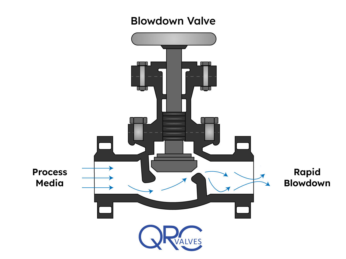
A safety valve, illustrated in Below Figure, rapidly pops fully open as soon as the pressure setting is reached. A safety valve will stay fully open until the pressure drops below a reset pressure.
The reset pressure is lower than the actuating pressure setpoint. The difference between the actuating pressure setpoint and the pressure at which the safety valve resets is called blowdown.
Relief valves are typically used for incompressible fluids such as water or oil. Safety valves are typically used for compressible fluids such as steam or other gases.
There are various types of safety valves used in several types of industries, including power plants, petrochemical plants, boilers, oil and gas, pharmaceuticals, and more. Using safety valves helps to prevent accidents and injuries that can harm people, property, and processes. Pressure builds up in vessels and systems automatically when the device is activated above a preset level. Safety valves must be configured so that their prescribed pressure is exceeded in order for them to function (i.e., relieve pressure). Ideally, excess pressure should be released either to the atmosphere or back into the pneumatic system to prevent damage to the vessel. In addition, excess pressure should be released to keep pressure within a certain range. As soon as a slight increase in pressure above the desired limit has lifted the safety valve, it opens.
As indicated in Below Figure, system pressure provides a force that is attempting to push the disk of the safety valve off its seat. Spring pressure on the stem is forcing the disk onto the seat.
At the pressure determined by spring compression, system pressure overcomes spring pressure and the relief valve opens. As system pressure is relieved, the valve closes when spring pressure again overcomes system pressure.
Most relief and safety valves open against the force of a compression spring. The pressure setpoint is adjusted by turning the adjusting nuts on top of the yoke to increase or decrease the spring compression.
Valve relief removes excessive pressure from a system by limiting its pressure level to a safe level. Often referred to as pressure relief valves (PRVs) or safety relief valves, these valves provide relief from pressure. The purpose of a relief valve is, for example, to adjust the pressure within a vessel or a system so that a specific level is maintained. The goal of a relief valve, unlike a safety valve, is not to prevent damage to the vessel; rather, it is to control the pressure limit of a system dynamically depending on the requirements. Conversely, safety valves have a maximum allowable pressure set at a certain level, which allows escaping liquid or gas whenever the pressure exceeds it, eliminating damage to the system. It is imperative that safety valves are installed in a control system to prevent the development of pressure fluctuations that can cause property damage, life loss, and environmental pollution.
The hydraulic system relies on a pressure relief system in order to regulate the running pressure. By allowing excess pressure to escape from the pressurized zone, pressure relief valves and safety valves prevent overpressure when the pressure in the system reaches a predefined limit. By venting excess pressure through a relief port, or returning it through a return line, a pneumatic system can enable the excess pressure to escape into the atmosphere. Pump-driven pressure generators and control media that cannot be vented into the atmosphere are typical examples of this type of application.
Excess pressure may be relieved from the system using relief valves and safety valves. The valve opening increases proportionally as the vessel pressure increases with the relief valve. Gradually opening the valve rather than abruptly releasing only a prescribed amount of fluid. As pressure is reduced, the release proceeds at this rate until the pressure drops. By contrast, an emergency safety valve operates automatically when a predetermined pressure is reached in the system, preventing a catastrophic system failure. When the system is under excessive stress, the safety valve regulates the pressure within the system and prevents overpressure.
Defining a “setpoint” is the process of defining a pressure level that triggers the device to vent excess pressure. Setpoint is different from pressure. Overpressure is prevented by setting these devices lower than the highest pressure the system can handle before overpressure occurs. Setting the device below this pressure prevents overpressure. The valve opens when pressure rises above the setpoint. A setpoint also known as the maximum allowable working pressure (MAWP) cannot be exceeded when deciding the pressure in pounds per square inch (PSIG). The adjustment points for safety valves are generally 3 percent above working pressures, while adjustment points for relief valves are 10% above working pressures.
Pressure in an auxiliary passage can be controlled by a safety valve as well as a relief valve by releasing excess pressure. Safety valves of this type are pressure-sensitive and reliable. Safety valves can be categorized according to their capacity and setpoint, although both terms often refer to safety valves. Self-opening devices open automatically when maximum allowable pressure has been reached rather than being manually activated to prevent over-pressurizing. Contrary to relief valves, safety valves are typically used for venting steam or vapor into the atmosphere. Relief valves regulate fluid flow and compressed air pressure and gases, whereas safety valves typically regulate steam and vapor venting. Put simply, relief valves are used for more gradual pressure control requiring accurate, dynamic systems, whereas safety valves are used for one set to prevent damage to a system.
Pilot-operated relief valves are designed to maintain pressure through the use of a small passage to the top of a piston that is connected to the stem such that system pressure closes the main relief valve.

Safety is of the utmost importance when dealing with pressure relief valves. The valve is designed to limit system pressure, and it is critical that they remain in working order to prevent an explosion. Explosions have caused far too much damage in companies over the years, and though pressurized tanks and vessels are equipped with pressure relief vales to enhance safety, they can fail and result in disaster.
That’s also why knowing the correct way to test the valves is important. Ongoing maintenance and periodic testing of pressurized tanks and vessels and their pressure relief valves keeps them in working order and keep employees and their work environments safe. Pressure relief valves must be in good condition in order to automatically lower tank and vessel pressure; working valves open slowly when the pressure gets high enough to exceed the pressure threshold and then closes slowly until the unit reaches the low, safe threshold. To ensure the pressure relief valve is in good working condition, employees must follow best practices for testing them including:
If you consider testing pressure relief valves a maintenance task, you’ll be more likely to carry out regular testing and ensure the safety of your organization and the longevity of your
It’s important to note, however, that the American Society of Mechanical Engineers (ASME) and National Board Inspection Code (NBIC), as well as state and local jurisdictions, may set requirements for testing frequency. Companies are responsible for checking with these organizations to become familiar with the testing requirements. Consider the following NBIC recommendations on the frequency for testing relief valves:
High-pressure steam boilers greater than 15 psi and less than 400 psi – perform manual check every six months and pressure test annually to verify nameplate set pressure
High-pressure steam boilers 400 psi and greater – pressure test to verify nameplate set pressure every three years or as determined by operating experience as verified by testing history
High-temperature hot water boilers (greater than 160 psi and/or 250 degrees Fahrenheit) – pressure test annually to verify nameplate set pressure. For safety reasons, removal and testing on a test bench is recommended
When testing the pressure relief valve, raise and lower the test lever several times. The lever will come away from the brass stem and allow hot water to come out of the end of the drainpipe. The water should flow through the pipe, and then you should turn down the pressure to stop the leak, replace the lever, and then increase the pressure.
One of the most common problems you can address with regular testing is the buildup of mineral salt, rust, and corrosion. When buildup occurs, the valve will become non-operational; the result can be an explosion. Regular testing helps you discover these issues sooner so you can combat them and keep your boiler and valve functioning properly. If no water flows through the pipe, or if there is a trickle instead of a rush of water, look for debris that is preventing the valve from seating properly. You may be able to operate the test lever a few times to correct the issue. You will need to replace the valve if this test fails.
When testing relief valves, keep in mind that they have two basic functions. First, they will pop off when the pressure exceeds its safety threshold. The valve will pop off and open to exhaust the excess pressure until the tank’s pressure decreases to reach the set minimum pressure. After this blowdown process occurs, the valve should reset and automatically close. One important testing safety measure is to use a pressure indicator with a full-scale range higher than the pop-off pressure.
Thus, you need to be aware of the pop-off pressure point of whatever tank or vessel you test. You always should remain within the pressure limits of the test stand and ensure the test stand is assembled properly and proof pressure tested. Then, take steps to ensure the escaping pressure from the valve is directed away from the operator and that everyone involved in the test uses safety shields and wears safety eye protection.
After discharge – Because pressure relief valves are designed to open automatically to relieve pressure in your system and then close, they may be able to open and close multiple times during normal operation and testing. However, when a valve opens, debris may get into the valve seat and prevent the valve from closing properly. After discharge, check the valve for leakage. If the leakage exceeds the original settings, you need to repair the valve.
According to local jurisdictional requirements – Regulations are in place for various locations and industries that stipulate how long valves may operate before needing to be repair or replaced. State inspectors may require valves to be disassembled, inspected, repaired, and tested every five years, for instance. If you have smaller valves and applications, you can test the valve by lifting the test lever. However, you should do this approximately once a year. It’s important to note that ASME UG136A Section 3 requires valves to have a minimum of 75% operating pressure versus the set pressure of the valve for hand lifting to be performed for these types of tests.
Depending on their service and application– The service and application of a valve affect its lifespan. Valves used for clean service like steam typically last at least 20 years if they are not operated too close to the set point and are part of a preventive maintenance program. Conversely, valves used for services such as acid service, those that are operated too close to the set point, and those exposed to dirt or debris need to be replaced more often.
Pressure relief valves serve a critical role in protecting organizations and employees from explosions. Knowing how and when to test and repair or replace them is essential.

In any complex piping system, one of the most serious scenarios considered during a safety or HAZOP study is over-pressurization. If the pressure in the system reaches a high enough pressure, rupture can occur, leading to expensive repairs, significant system downtime, and even loss of life. In most cases, proper use of relief valves can mitigate or avoid pressure-induced rupture. Fortunately, AFT software can be used to easily and accurately model relief valves in a variety of scenarios, assisting engineers in designing safe and reliable systems.
All three major AFT products – AFT Fathom, AFT Arrow, and AFT Impulse – are capable of modeling relief valves for the conditions each are designed for. AFT Fathom and AFT Arrow can help show if the steady state scenario will ever reach the relief valve set point, and how that system will operate after the relief valve is opened. AFT Impulse can help understand how the valve will behave during both steady state and transient operation, and how the system as a whole will respond to various transient events.
To model relief valves, AFT Impulse provides four valve profile templates plus a general profile option that allows the user to specify a unique valve design, and are outlined in red in Figure 1 below. These four profiles include: Passive: the valve opens and closes based on pressure forces. Typical passive valves are constructed using a spring to keep the valve closed below the set point and to close it as the pressure is lowered.
Pilot Operated: the valve opens and closes based on pressure forces. Typical Pilot Operated Relief Valves (PORVs) use a hydraulic fluid on the back side of the valve to hold the valve closed. This fluid can either be a separate system or connected to a remote location in the network.
Rupture Disk: the valve opens at a set pressure and does not close. Rupture disks are often used when quick response is needed to avert an infrequent but serious over-pressurization scenario.
Surge Anticipator: the valve opens and closes based on pressure forces. Typical surge anticipating valves are operated similarly to a remote sensing pilot operated valve, with the system working to dampen pressure waves traveling through a system.
The General Profile option allows the user to create their own valve, allowing it to open and close instantaneously, along a defined time-Cv path, or based on pressure forces. With this General Profile option, when the user selects "Time" for the opening or closing profile, they are then able to go to the Transient tab, where they can enter information to define that transient profile.
Below the Profiles section, the Valve Setpoints section allows the user to define operating points of the valve. The Set Pressure defines the pressure at which the valve begins to open, the Overpressure defines when the valve is fully open, and the Blowdown Pressure defines when the valve closes.
Furthermore, all types of relief valves modeled in AFT Impulse can be modeled as either hydraulically balanced (with constant backpressure) or not. When the valve is balanced, the valve mechanism is independent of downstream pressure, and the set points can be defined based on the actual upstream pressure. When the valve is not balanced, the backpressure on the valve is not constant, and the set points are based on pressure differential with the downstream conditions.
The rest of the input for relief valves in AFT Impulse is similar to any other valve junction in the software. Users can input loss modeling information for their valve, allowing AFT Impulse to accurately determine flow through the relief valve while it is open. They can also add in Design Alerts, notifying the engineer if any set of events happens to the valve including it opening or reaching a specific pressure or flow rate.
With these options, virtually any relief valve design can be modeled during transient events, allowing their effects on the rest of the system to be accurately determined. Let"s take a look at how different relief valves affect a system in AFT Impulse.
The system we"ll look at, depicted in Figure 2 above, has pump J2 trip with inertia 5 seconds into the simulation, while valve J4 closes linearly over the first 2 seconds of the simulation. Notice that pipe P2 is 10,000 feet long, meaning the pressure wave generated in the system takes some time to travel back and forth, allowing us to see pressure surges relatively spaced out.
First, let"s look at how the system operates with and without a relief valve. Figure 3a below shows the inputs used for the relief valve in the system, while Figure 3b plots the static pressure just upstream from valve J4 over a 30 second period. As the graph shows, not including a relief valve in the system could subject the valve to serious forces, while a relief valve and surge tank system is able to keep the pressure close to the normal operating conditions.
Next, let"s look at how different types of relief valves affect the system. Figure 4 below, compares two different relief valves: a rupture disk set to 300 psia and the same passive relief valve shown in Figure 3a. As the graph shows, both systems rapidly pressurize and open after only a few seconds. However, because the system with a rupture disk releases most of the system pressure when the system first passes 300 psia, the pressure quickly drops towards the system pressure and experiences substantially reduced pressure variations at later times.
As evidenced by these two examples, modeling relief valves in AFT Impulse gives engineers the ability to analyze and understand which types and designs are best for their system. It allows them to understand how a relief valve will perform in the context of potential over-pressure events, during system design, and before those events happen during operation.
This discussion of relief valve design gives a good starting point for effectively and accurately creating models in all AFT software products. As with any aspect of system modeling, this topic has far more nuance and complexity than discussed here. For further help with relief valves – or any other topic – reach out to AFT"s support group at This email address is being protected from spambots. You need JavaScript enabled to view it..

An overpressure event refers to any condition which would cause pressure in a vessel or system to increase beyond the specified design pressure or maximum allowable working pressure (MAWP).
Many electronic, pneumatic and hydraulic systems exist today to control fluid system variables, such as pressure, temperature and flow. Each of these systems requires a power source of some type, such as electricity or compressed air in order to operate. A pressure Relief Valve must be capable of operating at all times, especially during a period of power failure when system controls are nonfunctional. The sole source of power for the pressure Relief Valve, therefore, is the process fluid.
Once a condition occurs that causes the pressure in a system or vessel to increase to a dangerous level, the pressure Relief Valve may be the only device remaining to prevent a catastrophic failure. Since reliability is directly related to the complexity of the device, it is important that the design of the pressure Relief Valve be as simple as possible.
The pressure Relief Valve must open at a predetermined set pressure, flow a rated capacity at a specified overpressure, and close when the system pressure has returned to a safe level. Pressure Relief Valves must be designed with materials compatible with many process fluids from simple air and water to the most corrosive media. They must also be designed to operate in a consistently smooth and stable manner on a variety of fluids and fluid phases.
The basic spring loaded pressure Relief Valve has been developed to meet the need for a simple, reliable, system actuated device to provide overpressure protection.
The Valve consists of a Valve inlet or nozzle mounted on the pressurized system, a disc held against the nozzle to prevent flow under normal system operating conditions, a spring to hold the disc closed, and a body/Bonnet to contain the operating elements. The spring load is adjustable to vary the pressure at which the Valve will open.
When a pressure Relief Valve begins to lift, the spring force increases. Thus system pressure must increase if lift is to continue. For this reason pressure Relief Valves are allowed an overpressure allowance to reach full lift. This allowable overpressure is generally 10% for Valves on unfired systems. This margin is relatively small and some means must be provided to assist in the lift effort.
Most pressure Relief Valves, therefore, have a secondary control chamber or huddling chamber to enhance lift. As the disc begins to lift, fluid enters the control chamber exposing a larger area of the disc to system pressure.
This causes an incremental change in force which overcompensates for the increase in spring force and causes the Valve to open at a rapid rate. At the same time, the direction of the fluid flow is reversed and the momentum effect resulting from the change in flow direction further enhances lift. These effects combine to allow the Valve to achieve maximum lift and maximum flow within the allowable overpressure limits. Because of the larger disc area exposed to system pressure after the Valve achieves lift, the Valve will not close until system pressure has been reduced to some level below the set pressure. The design of the control chamber determines where the closing point will occur.
When superimposed back pressure is variable, a balanced bellows or balanced piston design is recommended. A typical balanced bellow is shown on the right. The bellows or piston is designed with an effective pressure area equal to the seat area of the disc. The Bonnet is vented to ensure that the pressure area of the bellows or piston will always be exposed to atmospheric pressure and to provide a telltale sign should the bellows or piston begin to leak. Variations in back pressure, therefore, will have no effect on set pressure. Back pressure may, however, affect flow.
A safety Valve is a pressure Relief Valve actuated by inlet static pressure and characterized by rapid opening or pop action. (It is normally used for steam and air services.)
A low-lift safety Valve is a safety Valve in which the disc lifts automatically such that the actual discharge area is determined by the position of the disc.
A full-lift safety Valve is a safety Valve in which the disc lifts automatically such that the actual discharge area is not determined by the position of the disc.
A Relief Valve is a pressure relief device actuated by inlet static pressure having a gradual lift generally proportional to the increase in pressure over opening pressure. It may be provided with an enclosed spring housing suitable for closed discharge system application and is primarily used for liquid service.
A safety Relief Valve is a pressure Relief Valve characterized by rapid opening or pop action, or by opening in proportion to the increase in pressure over the opening pressure, depending on the application and may be used either for liquid or compressible fluid.
A conventional safety Relief Valve is a pressure Relief Valve which has its spring housing vented to the discharge side of the Valve. The operational characteristics (opening pressure, closing pressure, and relieving capacity) are directly affected by changes of the back pressure on the Valve.
A balanced safety Relief Valve is a pressure Relief Valve which incorporates means of minimizing the effect of back pressure on the operational characteristics (opening pressure, closing pressure, and relieving capacity).
A pilotoperated pressure Relief Valve is a pressure Relief Valve in which the major relieving device is combined with and is controlled by a self-actuated auxiliary pressure Relief Valve.
A poweractuated pressure Relief Valve is a pressure Relief Valve in which the major relieving device is combined with and controlled by a device requiring an external source of energy.
A temperature-actuated pressure Relief Valve is a pressure Relief Valve which may be actuated by external or internal temperature or by pressure on the inlet side.
A vacuum Relief Valve is a pressure relief device designed to admit fluid to prevent an excessive internal vacuum; it is designed to reclose and prevent further flow of fluid after normal conditions have been restored.
Many Codes and Standards are published throughout the world which address the design and application of pressure Relief Valves. The most widely used and recognized of these is the ASME Boiler and Pressure Vessel Code, commonly called the ASME Code.
Most Codes and Standards are voluntary, which means that they are available for use by manufacturers and users and may be written into purchasing and construction specifications. The ASME Code is unique in the United States and Canada, having been adopted by the majority of state and provincial legislatures and mandated by law.
The ASME Code provides rules for the design and construction of pressure vessels. Various sections of the Code cover fired vessels, nuclear vessels, unfired vessels and additional subjects, such as welding and nondestructive examination. Vessels manufactured in accordance with the ASME Code are required to have overpressure protection. The type and design of allowable overpressure protection devices is spelled out in detail in the Code.
The following definitions are taken from DIN 3320 but it should be noted that many of the terms and associated definitions used are universal and appear in many other standards. Where commonly used terms are not defined in DIN 3320 then ASME PTC25.3 has been used as the source of reference. This list is not exhaustive and is intended as a guide only; it should not be used in place of the relevant current issue standard..
is the gauge pressure at which the lift is sufficient to discharge the predetermined flowing capacity. It is equal to the set pressure plus opening pressure difference.
is the cross sectional area upstream or downstream of the body seat calculated from the minimum diameter which is used to calculate the flow capacity without any deduction for obstructions.
is the calculated mass flow from an orifice having a cross sectional area equal to the flow area of the safety Valve without regard to flow losses of the Valve.
the pressure at which a Valve is set on a test rig using a test fluid at ambient temperature. This test pressure includes corrections for service conditions e.g. backpressure or high temperatures.
is that portion of the measured relieving capacity permitted by the applicable code or regulation to be used as a basis for the application of a pressure relieving device.
is the value of increasing static inlet pressure of a pressure Relief Valve at which there is a measurable lift, or at which the discharge becomes continuous as determined by seeing, feeling or hearing.
is the maximum allowable working pressure plus the accumulation as established by reference to the applicable codes for operating or fire contingencies.
Because cleanliness is essential to the satisfactory operation and tightness of a safety Valve, precautions should be taken during storage to keep out all foreign materials. Inlet and outlet protectors should remain in place until the Valve is ready to be installed in the system. Take care to keep the Valve inlet absolutely clean. It is recommended that the Valve be stored indoors in the original shipping container away from dirt and other forms of contamination.
Safety Valves must be handled carefully and never subjected to shocks. Rough handling may alter the pressure setting, deform Valve parts and adversely affect seat tightness and Valve performance.
When it is necessary to use a hoist, the chain or sling should be placed around the Valve body and Bonnet in a manner that will insure that the Valve is in a vertical position to facilitate installation.
Many Valves are damaged when first placed in service because of failure to clean the connection properly when installed. Before installation, flange faces or threaded connections on both the Valve inlet and the vessel and/or line on which the Valve is mounted must be thoroughly cleaned of all dirt and foreign material.
Because foreign materials that pass into and through safety Valves can damage the Valve, the systems on which the Valves are tested and finally installed must also be inspected and cleaned. New systems in particular are prone to contain foreign objects that inadvertently get trapped during construction and will destroy the seating surface when the Valve opens. The system should be thoroughly cleaned before the safety Valve is installed.
The gaskets used must be dimensionally correct for the specific flanges. The inside diameters must fully clear the safety Valve inlet and outlet openings so that the gasket does not restrict flow.
For flanged Valves, draw down all connection studs or bolts evenly to avoid possible distortion of the Valve body. For threaded Valves, do not apply a wrench to the Valve body. Use the hex flats provided on the inlet bushing.
Safety Valves are intended to open and close within a narrow pressure range. Valve installations require accurate design both as to inlet and discharge piping. Refer to International, National and Industry Standards for guidelines.
The Valve should be mounted vertically in an upright position either directly on a nozzle from the pressure vessel or on a short connection fitting that provides a direct, unobstructed flow between the vessel and the Valve. Installing a safety Valve in other than this recommended position will adversely affect its operation.
Discharge piping should be simple and direct. A "broken" connection near the Valve outlet is preferred wherever possible. All discharge piping should be run as direct as is practicable to the point of final release for disposal. The Valve must discharge to a safe disposal area. Discharge piping must be drained properly to prevent the accumulation of liquids on the downstream side of the safety Valve.
The weight of the discharge piping should be carried by a separate support and be properly braced to withstand reactive thrust forces when the Valve relieves. The Valve should also be supported to withstand any swaying or system vibrations.
If the Valve is discharging into a pressurized system be sure the Valve is a "balanced" design. Pressure on the discharge of an "unbalanced" design will adversely affect the Valve performance and set pressure.
The Bonnets of balanced bellows safety Valves must always be vented to ensure proper functioning of the Valve and to provide a telltale in the event of a bellows failure. Do not plug these open vents. When the fluid is flammable, toxic or corrosive, the Bonnet vent should be piped to a safe location.
It is important to remember that a pressure Relief Valve is a safety device employed to protect pressure vessels or systems from catastrophic failure. With this in mind, the application of pressure Relief Valves should be assigned only to fully trained personnel and be in strict compliance with rules provided by the governing codes and standards.

(a) Safety valves and pressure relief valves. (1) The use of weighted-lever safety valves, or safety valves having either the seat or disk of cast iron, is prohibited. (2) Each boiler shall have at least one safety valve and, if it has more than 500 square feet (47 square meters) of bare tube water heating surface or has electric power input more than 1,100 kilowatts, it shall have two or more safety valves. These valves shall be "V" stamped per ASME Code. (3) Safety valves or pressure relief valves shall be connected so as to stand in the upright position, with spindle vertical. The opening or connection between the boiler and the safety valve or pressure relief valve shall have at least the area of the valve inlet. (4) The valve or valves shall be connected to the boiler, independent of any other steam connection, and attached as close as practicable to the boiler without unnecessary intervening pipe or fittings. (5) Except for changeover valves as defined in §65.2(14), other valve(s) shall not be placed: (A) between the required safety valve or pressure relief valve or valves and the boiler; or (B) in the discharge pipe between the safety valve or pressure relief valve or valves and the atmosphere. (6) When a discharge pipe is used, it shall be: (A) at least full size of the safety valve discharge; and (B) fitted with an open drain to prevent water lodging in the upper part of the safety valve or discharge pipe. (7) When an elbow is placed on a safety valve discharge pipe: (A) it shall be located close to the safety valve outlet; and (B) the discharge pipe shall be securely anchored and supported. (8) In the event multiple safety valves discharge into a common pipe, the discharge pipe shall be sized in accordance with ASME Code, Section I, PG-71. (9) All safety valve or pressure relief valve discharges shall be located or piped to a safe point of discharge, clear from walkways or platforms. (10) If a muffler is used on a pressure relief valve, it shall have sufficient area to prevent back pressure from interfering with the proper operation and discharge capacity of the valve. Mufflers shall not be used on High-Temperature Water Boilers. (11) The safety valve capacity of each boiler must allow the safety valve or valves to discharge all the steam that can be generated by the boiler without allowing the pressure to rise more than 6.0% above the highest pressure to which any valve is set, and to no more than 6.0% above the MAWP. For forced-flow steam generators with no fixed steam and waterline, power-actuated relieving valves may be used in accordance with ASME Code, Section I, PG-67. (12) One or more safety valves on every drum type boiler shall be set at or below the MAWP. The remaining valve(s) may be set within a range of 3.0% above the MAWP, but the range of setting of all the drum mounted pressure relief valves on a boiler shall not exceed 10% of the highest pressure to which any valve is set. (13) When two or more boilers, operating at different pressures and safety valve settings, are interconnected, the lower pressure boilers or interconnected piping shall be equipped with safety valves of sufficient capacity to prevent overpressure, considering the maximum generating capacity of all boilers. (14) In those cases where the boiler is supplied with feedwater directly from water mains without the use of feeding apparatus (not to include return traps), no safety valve shall be set at a pressure higher than 94% of the lowest pressure obtained in the supply main feeding the boilers. (b) Feedwater supply. (1) Each boiler shall have a feedwater supply, which will permit it to be fed at any time while under pressure, except for automatically fired miniature boilers that meet all of the following criteria: (A) the boiler is "M" stamped per ASME Code, Section I; (B) the boiler is designed to be fed manually; (C) the boiler is provided with a means to prevent cold water from entering into a hot boiler; and (D) the boiler is equipped with a warning sign visible to the operator not to introduce cold feedwater into a hot boiler. (2) A boiler having more than 500 square feet (47 square meters) of water heating surface, shall have at least two means of feeding, one of which should be a pump, injector, or inspirator. A source of feed directly from water mains at a pressure of at least 6.0% greater than the set pressure of the safety valve with the highest setting may be considered as one of the means of feeding. Boilers fired by gaseous, liquid, or solid fuel in suspension may be equipped with a single means of feeding water, provided means are furnished for the immediate shutoff of heat input if the feedwater is interrupted. (3) Feedwater shall not be discharged close to riveted joints of shell or furnace sheets or directly against surfaces exposed to products of combustion or to direct radiation from the fire. (4) Feedwater piping to the boiler shall be provided with a check valve near the boiler and a stop valve or cock between the check valve and the boiler. When two or more boilers are fed from a common source, there shall also be a stop valve on the branch to each boiler between the check valve and the source of supply. Whenever a globe valve is used on the feedwater piping, the inlet shall be under the disk of the valve. (5) In all cases where returns are fed back to the boiler by gravity, there shall be a check valve and stop valve in each return line, the stop valve to be placed between boiler and the check valve, and both shall be located as close to the boiler as is practicable. Best practice is that no stop valve be placed in the supply and return pipe connections of a single boiler installation. (6) Where deaerating heaters are not used, best practice is that the temperature of the feedwater be not less than 120 degrees Fahrenheit (49 degrees Celsius), to avoid the possibility of setting up localized stress. Where deaerating heaters are used, best practice is for the minimum feedwater temperature be not less than 215 degrees Fahrenheit (102 degrees Celsius), so that dissolved gases may be thoroughly released. (c) Water level indicators. (1) Each boiler, except forced-flow steam generators with no fixed steam and waterline, and high-temperature water boilers of the forced circulation type that have no steam and waterline shall have at least one water gage glass. (2) Except for electric boilers of the electrode type, boilers with a MAWP over 400 psig (three (3) megapascals) shall be provided with two water gage glasses, which may be connected to a single water column or connected directly to the drum. (3) Two independent remote level indicators may be provided instead of one of the two required gage glasses for boiler drum water level indication, when the MAWP is above 400 psig (three (3) megapascals). When both remote level indicators are in reliable operation, the remaining gage glass may be shut off, but shall be maintained in serviceable condition. (4) In all installations where direct visual observations of the water gage glass(es) cannot be made, two remote level indicators shall be provided at operational level. (5) The gage glass cock connections shall not be less than 1/2 inch nominal pipe size (15 mm). (6) No outlet connections, except for damper regulator, feedwater regulator, drains, steam gages, or apparatus of such form as does not permit the escape of an appreciable amount of steam or water there from, shall be placed in the pipes connecting a water column or gage glass to a boiler. (7) The water column shall be fitted with a drain cock or drain valve of at least 3/4 inch nominal pipe size (20 mm). The water column blowdown pipe shall not be less than 3/4 inch nominal pipe size (20 mm), and shall be piped to a safe point of discharge. (8) Connections from the boiler to remote level indicators shall be at least 3/4 inch nominal


 8613371530291