
boiler safety valve diagram brands

There is a wide range of safety valves available to meet the many different applications and performance criteria demanded by different industries. Furthermore, national standards define many varying types of safety valve.
The ASME standard I and ASME standard VIII for boiler and pressure vessel applications and the ASME/ANSI PTC 25.3 standard for safety valves and relief valves provide the following definition. These standards set performance characteristics as well as defining the different types of safety valves that are used:
ASME I valve - A safety relief valve conforming to the requirements of Section I of the ASME pressure vessel code for boiler applications which will open within 3% overpressure and close within 4%. It will usually feature two blowdown rings, and is identified by a National Board ‘V’ stamp.
ASME VIII valve- A safety relief valve conforming to the requirements of Section VIII of the ASME pressure vessel code for pressure vessel applications which will open within 10% overpressure and close within 7%. Identified by a National Board ‘UV’ stamp.
Full bore safety valve - A safety valve having no protrusions in the bore, and wherein the valve lifts to an extent sufficient for the minimum area at any section, at or below the seat, to become the controlling orifice.
Conventional safety relief valve -The spring housing is vented to the discharge side, hence operational characteristics are directly affected by changes in the backpressure to the valve.
Balanced safety relief valve -A balanced valve incorporates a means of minimising the effect of backpressure on the operational characteristics of the valve.
Pilot operated pressure relief valve -The major relieving device is combined with, and is controlled by, a self-actuated auxiliary pressure relief device.
Power-actuated safety relief valve - A pressure relief valve in which the major pressure relieving device is combined with, and controlled by, a device requiring an external source of energy.
Standard safety valve - A valve which, following opening, reaches the degree of lift necessary for the mass flowrate to be discharged within a pressure rise of not more than 10%. (The valve is characterised by a pop type action and is sometimes known as high lift).
Full lift (Vollhub) safety valve -A safety valve which, after commencement of lift, opens rapidly within a 5% pressure rise up to the full lift as limited by the design. The amount of lift up to the rapid opening (proportional range) shall not be more than 20%.
Direct loaded safety valve -A safety valve in which the opening force underneath the valve disc is opposed by a closing force such as a spring or a weight.
Proportional safety valve - A safety valve which opens more or less steadily in relation to the increase in pressure. Sudden opening within a 10% lift range will not occur without pressure increase. Following opening within a pressure of not more than 10%, these safety valves achieve the lift necessary for the mass flow to be discharged.
Diaphragm safety valve -A direct loaded safety valve wherein linear moving and rotating elements and springs are protected against the effects of the fluid by a diaphragm
Bellows safety valve - A direct loaded safety valve wherein sliding and (partially or fully) rotating elements and springs are protected against the effects of the fluids by a bellows. The bellows may be of such a design that it compensates for influences of backpressure.
Controlled safety valve - Consists of a main valve and a control device. It also includes direct acting safety valves with supplementary loading in which, until the set pressure is reached, an additional force increases the closing force.
Safety valve - A safety valve which automatically, without the assistance of any energy other than that of the fluid concerned, discharges a quantity of the fluid so as to prevent a predetermined safe pressure being exceeded, and which is designed to re-close and prevent further flow of fluid after normal pressure conditions of service have been restored. Note; the valve can be characterised either by pop action (rapid opening) or by opening in proportion (not necessarily linear) to the increase in pressure over the set pressure.
Direct loaded safety valve -A safety valve in which the loading due to the fluid pressure underneath the valve disc is opposed only by a direct mechanical loading device such as a weight, lever and weight, or a spring.
Assisted safety valve -A safety valve which by means of a powered assistance mechanism, may additionally be lifted at a pressure lower than the set pressure and will, even in the event of a failure of the assistance mechanism, comply with all the requirements for safety valves given in the standard.
Supplementary loaded safety valve - A safety valve that has, until the pressure at the inlet to the safety valve reaches the set pressure, an additional force, which increases the sealing force.
Note; this additional force (supplementary load), which may be provided by means of an extraneous power source, is reliably released when the pressure at the inlet of the safety valve reaches the set pressure. The amount of supplementary loading is so arranged that if such supplementary loading is not released, the safety valve will attain its certified discharge capacity at a pressure not greater than 1.1 times the maximum allowable pressure of the equipment to be protected.
Pilot operated safety valve -A safety valve, the operation of which is initiated and controlled by the fluid discharged from a pilot valve, which is itself, a direct loaded safety valve subject to the requirement of the standard.
The common characteristic shared between the definitions of conventional safety valves in the different standards, is that their operational characteristics are affected by any backpressure in the discharge system. It is important to note that the total backpressure is generated from two components; superimposed backpressure and the built-up backpressure:
Subsequently, in a conventional safety valve, only the superimposed backpressure will affect the opening characteristic and set value, but the combined backpressure will alter the blowdown characteristic and re-seat value.
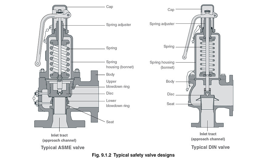
The ASME/ANSI standard makes the further classification that conventional valves have a spring housing that is vented to the discharge side of the valve. If the spring housing is vented to the atmosphere, any superimposed backpressure will still affect the operational characteristics. Thiscan be seen from Figure 9.2.1, which shows schematic diagrams of valves whose spring housings are vented to the discharge side of the valve and to the atmosphere.
By considering the forces acting on the disc (with area AD), it can be seen that the required opening force (equivalent to the product of inlet pressure (PV) and the nozzle area (AN)) is the sum of the spring force (FS) and the force due to the backpressure (PB) acting on the top and bottom of the disc. In the case of a spring housing vented to the discharge side of the valve (an ASME conventional safety relief valve, see Figure 9.2.1 (a)), the required opening force is:
In both cases, if a significant superimposed backpressure exists, its effects on the set pressure need to be considered when designing a safety valve system.
Once the valve starts to open, the effects of built-up backpressure also have to be taken into account. For a conventional safety valve with the spring housing vented to the discharge side of the valve, see Figure 9.2.1 (a), the effect of built-up backpressure can be determined by considering Equation 9.2.1 and by noting that once the valve starts to open, the inlet pressure is the sum of the set pressure, PS, and the overpressure, PO.
Balanced safety valves are those that incorporate a means of eliminating the effects of backpressure. There are two basic designs that can be used to achieve this:
Although there are several variations of the piston valve, they generally consist of a piston type disc whose movement is constrained by a vented guide. The area of the top face of the piston, AP, and the nozzle seat area, AN, are designed to be equal. This means that the effective area of both the top and bottom surfaces of the disc exposed to the backpressure are equal, and therefore any additional forces are balanced. In addition, the spring bonnet is vented such that the top face of the piston is subjected to atmospheric pressure, as shown in Figure 9.2.2.
The bellows arrangement prevents backpressure acting on the upper side of the disc within the area of the bellows. The disc area extending beyond the bellows and the opposing disc area are equal, and so the forces acting on the disc are balanced, and the backpressure has little effect on the valve opening pressure.
Bellows failure is an important concern when using a bellows balanced safety valve, as this may affect the set pressure and capacity of the valve. It is important, therefore, that there is some mechanism for detecting any uncharacteristic fluid flow through the bellows vents. In addition, some bellows balanced safety valves include an auxiliary piston that is used to overcome the effects of backpressure in the case of bellows failure. This type of safety valve is usually only used on critical applications in the oil and petrochemical industries.
Since balanced pressure relief valves are typically more expensive than their unbalanced counterparts, they are commonly only used where high pressure manifolds are unavoidable, or in critical applications where a very precise set pressure or blowdown is required.
This type of safety valve uses the flowing medium itself, through a pilot valve, to apply the closing force on the safety valve disc. The pilot valve is itself a small safety valve.
The diaphragm type is typically only available for low pressure applications and it produces a proportional type action, characteristic of relief valves used in liquid systems. They are therefore of little use in steam systems, consequently, they will not be considered in this text.
The piston type valve consists of a main valve, which uses a piston shaped closing device (or obturator), and an external pilot valve. Figure 9.2.4 shows a diagram of a typical piston type, pilot operated safety valve.
The piston and seating arrangement incorporated in the main valve is designed so that the bottom area of the piston, exposed to the inlet fluid, is less than the area of the top of the piston. As both ends of the piston are exposed to the fluid at the same pressure, this means that under normal system operating conditions, the closing force, resulting from the larger top area, is greater than the inlet force. The resultant downward force therefore holds the piston firmly on its seat.
If the inlet pressure were to rise, the net closing force on the piston also increases, ensuring that a tight shut-off is continually maintained. However, when the inlet pressure reaches the set pressure, the pilot valve will pop open to release the fluid pressure above the piston. With much less fluid pressure acting on the upper surface of the piston, the inlet pressure generates a net upwards force and the piston will leave its seat. This causes the main valve to pop open, allowing the process fluid to be discharged.
When the inlet pressure has been sufficiently reduced, the pilot valve will reclose, preventing the further release of fluid from the top of the piston, thereby re-establishing the net downward force, and causing the piston to reseat.
Pilot operated safety valves offer good overpressure and blowdown performance (a blowdown of 2% is attainable). For this reason, they are used where a narrow margin is required between the set pressure and the system operating pressure. Pilot operated valves are also available in much larger sizes, making them the preferred type of safety valve for larger capacities.
One of the main concerns with pilot operated safety valves is that the small bore, pilot connecting pipes are susceptible to blockage by foreign matter, or due to the collection of condensate in these pipes. This can lead to the failure of the valve, either in the open or closed position, depending on where the blockage occurs.
The terms full lift, high lift and low lift refer to the amount of travel the disc undergoes as it moves from its closed position to the position required to produce the certified discharge capacity, and how this affects the discharge capacity of the valve.
A full lift safety valve is one in which the disc lifts sufficiently, so that the curtain area no longer influences the discharge area. The discharge area, and therefore the capacity of the valve are subsequently determined by the bore area. This occurs when the disc lifts a distance of at least a quarter of the bore diameter. A full lift conventional safety valve is often the best choice for general steam applications.
The disc of a high lift safety valve lifts a distance of at least 1/12th of the bore diameter. This means that the curtain area, and ultimately the position of the disc, determines the discharge area. The discharge capacities of high lift valves tend to be significantly lower than those of full lift valves, and for a given discharge capacity, it is usually possible to select a full lift valve that has a nominal size several times smaller than a corresponding high lift valve, which usually incurs cost advantages.Furthermore, high lift valves tend to be used on compressible fluids where their action is more proportional.
In low lift valves, the disc only lifts a distance of 1/24th of the bore diameter. The discharge area is determined entirely by the position of the disc, and since the disc only lifts a small amount, the capacities tend to be much lower than those of full or high lift valves.
Except when safety valves are discharging, the only parts that are wetted by the process fluid are the inlet tract (nozzle) and the disc. Since safety valves operate infrequently under normal conditions, all other components can be manufactured from standard materials for most applications. There are however several exceptions, in which case, special materials have to be used, these include:
Cast steel -Commonly used on higher pressure valves (up to 40 bar g). Process type valves are usually made from a cast steel body with an austenitic full nozzle type construction.
For all safety valves, it is important that moving parts, particularly the spindle and guides are made from materials that will not easily degrade or corrode. As seats and discs are constantly in contact with the process fluid, they must be able to resist the effects of erosion and corrosion.
The spring is a critical element of the safety valve and must provide reliable performance within the required parameters. Standard safety valves will typically use carbon steel for moderate temperatures. Tungsten steel is used for higher temperature, non-corrosive applications, and stainless steel is used for corrosive or clean steam duty. For sour gas and high temperature applications, often special materials such as monel, hastelloy and ‘inconel’ are used.
Standard safety valves are generally fitted with an easing lever, which enables the valve to be lifted manually in order to ensure that it is operational at pressures in excess of 75% of set pressure. This is usually done as part of routine safety checks, or during maintenance to prevent seizing. The fitting of a lever is usually a requirement of national standards and insurance companies for steam and hot water applications. For example, the ASME Boiler and Pressure Vessel Code states that pressure relief valves must be fitted with a lever if they are to be used on air, water over 60°C, and steam.
A test gag (Figure 9.2.7) may be used to prevent the valve from opening at the set pressure during hydraulic testing when commissioning a system. Once tested, the gag screw is removed and replaced with a short blanking plug before the valve is placed in service.
The amount of fluid depends on the particular design of safety valve. If emission of this fluid into the atmosphere is acceptable, the spring housing may be vented to the atmosphere – an open bonnet. This is usually advantageous when the safety valve is used on high temperature fluids or for boiler applications as, otherwise, high temperatures can relax the spring, altering the set pressure of the valve. However, using an open bonnet exposes the valve spring and internals to environmental conditions, which can lead to damage and corrosion of the spring.
When the fluid must be completely contained by the safety valve (and the discharge system), it is necessary to use a closed bonnet, which is not vented to the atmosphere. This type of spring enclosure is almost universally used for small screwed valves and, it is becoming increasingly common on many valve ranges since, particularly on steam, discharge of the fluid could be hazardous to personnel.
Some safety valves, most commonly those used for water applications, incorporate a flexible diaphragm or bellows to isolate the safety valve spring and upper chamber from the process fluid, (see Figure 9.2.9).

The S100 Safety Shut Off valve is mainly used to avoid any damage to components as well as to avoid too high or too low pressure in the gas train. This could cause high financial losses and/or injured ...
130 Series Safety valves are also available as Relief valves. Relief valves, identified by the letter R after the type number, are devices with an operational function, ...
Parker"s cartridge safety relief valves (CSRV) are designed to offer the highest level of protection while maintaining easy serviceability. The CSRV was designed from the existing Parker ...
Boiler explosions have been responsible for widespread damage to companies throughout the years, and that’s why today’s boilers are equipped with safety valves and/or relief valves. Boiler safety valves are designed to prevent excess pressure, which is usually responsible for those devastating explosions. That said, to ensure that boiler safety valves are working properly and providing adequate protection, they must meet regulatory specifications and require ongoing maintenance and periodic testing. Without these precautions, malfunctioning safety valves may fail, resulting in potentially disastrous consequences.
Boiler safety valves are activated by upstream pressure. If the pressure exceeds a defined threshold, the valve activates and automatically releases pressure. Typically used for gas or vapor service, boiler safety valves pop fully open once a pressure threshold is reached and remain open until the boiler pressure reaches a pre-defined, safe lower pressure.
Boiler relief valves serve the same purpose – automatically lowering boiler pressure – but they function a bit differently than safety valves. A relief valve doesn’t open fully when pressure exceeds a defined threshold; instead, it opens gradually when the pressure threshold is exceeded and closes gradually until the lower, safe threshold is reached. Boiler relief valves are typically used for liquid service.
There are also devices known as “safety relief valves” which have the characteristics of both types discussed above. Safety relief valves can be used for either liquid or gas or vapor service.
Nameplates must be fastened securely and permanently to the safety valve and remain readable throughout the lifespan of the valve, so durability is key.
The National Board of Boiler and Pressure Vessel Inspectors offers guidance and recommendations on boiler and pressure vessel safety rules and regulations. However, most individual states set forth their own rules and regulations, and while they may be similar across states, it’s important to ensure that your boiler safety valves meet all state and local regulatory requirements.
The National Board published NB-131, Recommended Boiler and Pressure Vessel Safety Legislation, and NB-132, Recommended Administrative Boiler and Pressure Vessel Safety Rules and Regulationsin order to provide guidance and encourage the development of crucial safety laws in jurisdictions that currently have no laws in place for the “proper construction, installation, inspection, operation, maintenance, alterations, and repairs” necessary to protect workers and the public from dangerous boiler and pressure vessel explosions that may occur without these safeguards in place.
The American Society of Mechanical Engineers (ASME) governs the code that establishes guidelines and requirements for safety valves. Note that it’s up to plant personnel to familiarize themselves with the requirements and understand which parts of the code apply to specific parts of the plant’s steam systems.
High steam capacity requirements, physical or economic constraints may make the use of a single safety valve impossible. In these cases, using multiple safety valves on the same system is considered an acceptable practice, provided that proper sizing and installation requirements are met – including an appropriately sized vent pipe that accounts for the total steam venting capacity of all valves when open at the same time.
The lowest rating (MAWP or maximum allowable working pressure) should always be used among all safety devices within a system, including boilers, pressure vessels, and equipment piping systems, to determine the safety valve set pressure.
Avoid isolating safety valves from the system, such as by installing intervening shut-off valves located between the steam component or system and the inlet.
Contact the valve supplier immediately for any safety valve with a broken wire seal, as this indicates that the valve is unsafe for use. Safety valves are sealed and certified in order to prevent tampering that can prevent proper function.
Avoid attaching vent discharge piping directly to a safety valve, which may place unnecessary weight and additional stress on the valve, altering the set pressure.

Years ago, it was not uncommon to read news about tragic boiler explosions, sometimes resulting in mass destruction. Today, boilers are equipped with important safety devises to help protect against these types of catastrophes. Let’s take a look at the most critical of these devices: the safety valve.
The safety valve is one of the most important safety devices in a steam system. Safety valves provide a measure of security for plant operators and equipment from over pressure conditions. The main function of a safety valve is to relieve pressure. It is located on the boiler steam drum, and will automatically open when the pressure of the inlet side of the valve increases past the preset pressure. All boilers are required by ASME code to have at least one safety valve, dependent upon the maximum flow capacity (MFC) of the boiler. The total capacity of the safety valve at the set point must exceed the steam control valve’s MFC if the steam valve were to fail to open. In most cases, two safety valves per boiler are required, and a third may be needed if they do not exceed the MFC.
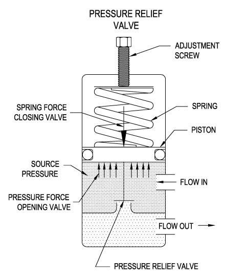
There are three main parts to the safety valve: nozzle, disc, and spring. Pressurized steam enters the valve through the nozzle and is then threaded to the boiler. The disc is the lid to the nozzle, which opens or closes depending on the pressure coming from the boiler. The spring is the pressure controller.
As a boiler starts to over pressure, the nozzle will start to receive a higher pressure coming from the inlet side of the valve, and will start to sound like it is simmering. When the pressure becomes higher than the predetermined pressure of the spring, the disc will start to lift and release the steam, creating a “pop” sound. After it has released and the steam and pressure drops below the set pressure of the valve, the spring will close the disc. Once the safety valve has popped, it is important to check the valve to make sure it is not damaged and is working properly.
A safety valve is usually referred to as the last line of safety defense. Without safety valves, the boiler can exceed it’s maximum allowable working pressure (MAWP) and not only damage equipment, but also injure or kill plant operators that are close by. Many variables can cause a safety valve on a boiler to lift, such as a compressed air or electrical power failure to control instrumentation, or an imbalance of feedwater rate caused by an inadvertently shut or open isolation valve.
Once a safety valve has lifted, it is important to do a complete boiler inspection and confirm that there are no other boiler servicing issues. A safety valve should only do its job once; safety valves should not lift continuously. Lastly, it is important to have the safety valves fully repaired, cleaned and recertified with a National Board valve repair (VR) stamp as required by local code or jurisdiction. Safety valves are a critical component in a steam system, and must be maintained.
All of Nationwide Boiler’s rental boilers include on to two safety valves depending on the size; one set at design pressure and the other set slightly higher than design. By request, we can reset the safeties to a lower pressure if the application requires it. In addition, the valves are thoroughly checked after every rental and before going out to a new customer, and they are replaced and re-certified as needed.

Pressure relief valves (safety relief valves) are designed to open at a preset pressure and discharge fluid until pressure drops to acceptable levels. The development of the safety relief valve has an interesting history.
Denis Papin is credited by many sources as the originator of the first pressure relief valve (circa 1679) to prevent overpressure of his steam powered “digester”. His pressure relief design consisted of a weight suspended on a lever arm. When the force of the steam pressure acting on the valve exceeded the force of the weight acting through the lever arm the valve opened. Designs requiring a higher relief pressure setting required a longer lever arm and/or larger weights. This simple system worked however more space was needed and it coud be easily tampered with leading to a possible overpressure and explosion. Another disadvantage was premature opening of the valve if the device was subjected to bouncing movement.
Direct-acting deadweight pressure relief valves: Later to avoid the disadvantages of the lever arrangement, direct-acting deadweight pressure relief valves were installed on early steam locomotives. In this design, weights were applied directly to the top of the valve mechanism. To keep the size of the weights in a reasonable range, the valve size was often undersized resulting in a smaller vent opening than required. Often an explosion would occur as the steam pressure rose faster than the vent could release excess pressure. Bouncing movements also prematurely released pressure.
Direct acting spring valves: Timothy Hackworth is believed to be the first to use direct acting spring valves (circa 1828) on his locomotive engine called the Royal George. Timothy utilized an accordion arrangement of leaf springs, which would later be replaced with coil springs, to apply force to the valve. The spring force could be fine tuned by adjusting the nuts retaining the leaf springs.
Refinements to the direct acting spring relief valve design continued in subsequent years in response to the widespread use of steam boilers to provide heat and to power locomotives, river boats, and pumps. Steam boilers are less common today but the safety relief valve continues to be a critical component, in systems with pressure vessels, to protect against damage or catastrophic failure.
Each application has its own unique requirements but before we get into the selection process, let’s have a look at the operating principles of a typical direct acting pressure relief valve.
In operation, the pressure relief valve remains normally closed until pressures upstream reaches the desired set pressure. The valve will crack open when the set pressure is reached, and continue to open further, allowing more flow as over pressure increases. When upstream pressure falls a few psi below the set pressure, the valve will close again.
Most commonly, pressure relief valves employ a spring loaded “poppet” valve as a valve element. The poppet includes an elastomeric seal or, in some high pressure designs a thermoplastic seal, which is configured to make a seal on a valve seat. In operation, the spring and upstream pressure apply opposing forces on the valve. When the force of the upstream pressure exerts a greater force than the spring force, then the poppet moves away from the valve seat which allows fluid to pass through the outlet port. As the upstream pressure drops below the set point the valve then closes.
Piston style designs are often used when higher relief pressures are required, when ruggedness is a concern or when the relief pressure does not have to be held to a tight tolerance. Piston designs tend to be more sluggish, compared to diaphragm designs due to friction from the piston seal. In low pressure applications, or when high accuracy is required, the diaphragm style is preferred. Diaphragm relief valves employ a thin disc shaped element which is used to sense pressure changes. They are usually made of an elastomer, however, thin convoluted metal is used in special applications. Diaphragms essentially eliminate the friction inherent with piston style designs. Additionally, for a particular relief valve size, it is often possible to provide a greater sensing area with a diaphragm design than would be feasible with a piston style design.
The reference force element is usually a mechanical spring. This spring exerts a force on the sensing element and acts to close the valve. Many pressure relief valves are designed with an adjustment which allows the user to adjust the relief pressure set-point by changing the force exerted by the reference spring.
The chemical properties of the fluid should be considered before determining the best materials for your application. Each fluid will have its own unique characteristics so care must be taken to select the appropriate body and seal materials that will come in contact with the fluid. The parts of the pressure relief valve in contact with the fluid are known as the “wetted” components. If the fluid is flammable or hazardous in nature the pressure relief valve must be capable of discharging it safely.
In many high technology applications space is limited and weight is a factor. Some manufactures specialize in miniature components and should be consulted. Material selection, particularly the relief valve body components, will impact weight. Also carefully consider the port (thread) sizes, adjustment styles, and mounting options as these will influence size and weight.
In many high technology applications space is limited and weight is a factor. Some manufactures specialize in miniature components and should be consulted. Material selection, particularly the relief valve body components, will impact weight. Also carefully consider the port (thread) sizes, adjustment styles, and mounting options as these will influence size and weight.
A wide range of materials are available to handle various fluids and operating environments. Common pressure relief valve component materials include brass, plastic, and aluminum. Various grades of stainless steel (such as 303, 304, and 316) are available too. Springs used inside the relief valve are typically made of music wire (carbon steel) or stainless steel.
The materials selected for the pressure relief valve not only need to be compatible with the fluid but also must be able to function properly at the expected operating temperature. The primary concern is whether or not the elastomer chosen will function properly throughout the expected temperature range. Additionally, the operating temperature may affect flow capacity and/or the spring rate in extreme applications.
Beswick Engineering manufactures four styles of pressure relief valves to best suit your application. The RVD and RVD8 are diaphragm based pressure relief valves which are suited to lower relief pressures. The RV2 and BPR valves are piston based designs.
Thermoglide design improves the gliding characteristics of internal parts thus enabling the valve to achieve its full lift and re-seat point within the fastest possible time
Safety valves or pressure relief valves are pressure regulating devices that are responsible for expelling excess pressure from the system when the maximum pressure levels for which they have been designed are exceeded, usually due to a
Safety valves perform their function when the pressure of the system where the fluid is contained, becomes higher than the maximum set pressure of the valve previously adjusted. When the system pressure is higher than the valve’s set
pressure, this opens, releasing the excess pressure to the atmosphere or to containment tanks, depending on the toxicity of the fluid. After releasing the excess, the valve closes again and the system pressure returns to normal.
To ensure total safety of personnel and installation, make sure that the valves have passed all safety tests and meet the requirements of the system where they are to be installed. All our valves are supplied with certificates of materials, cas-
What is the difference between the instantaneous full opening safety valve AIT (PSV) and the normal opening relief valve AN or progressive opening relief valve AP (PRV)?
The Pressure Safety Valve (PSV) opens instantaneously and fully upon reaching the set pressure for which it is designed, expelling the excess pressure from the system immediately. They are optimised for use with steam or gases.
In contrast, the normally or progressively opening Pressure Relief Valve (PRV) opens gradually as the system pressure rises above the set pressure of the valve above its setting. They are optimised to work with liquids.
At VYC Industrial we are specialists in the design and manufacture of all types of safety valves. We have a wide range of safety valves to cover all the needs of the sector.
The Mod. 496 EN safety valve works as an automatic pressure releasing regulator activated by the static pressure existing at the entrance to the valve and is characterized by its ability to open instantly and totally.
The Mod. 495 EN pressure relief valve works as an automatic pressure releasing regulator activated by the static pressure existing at the entrance to the valve and is characterized by its ability to open instantly and totally.
The relief valve works as an automatic pressure releasing regulator activated by the static pressure existing at the entrance to the valve and is characterized by its ability to open instantly and totally.
The valve works as an automatic pressure releasing regulator activated by the static pressure existing at the entrance to the valve and is characterized by its ability to open instantly and totally.
The valve works as an automatic pressure releasing regulator activated by the static pressure existing at the entrance to the valve and is characterized by its ability to open instantly and totally.
The valve works as an automatic pressure releasing regulator activated by the static pressure existing at the entrance to the valve and is characterized by its ability to open instantly and totally.
The valve works as an automatic pressure releasing regulator activated by the static pressure existing at the entrance to the valve and is characterized by its ability to open instantly and totally.
The valve works as an automatic pressure releasing regulator activated by the static pressure existing at the entrance to the valve and is characterized by its ability to open instantly and totally.
The valve works as an automatic pressure releasing regulator activated by the static pressure existing at the entrance to the valve and is characterized by its ability to open, at the fi rst proportional to the pressure increase, and after instantly and totally.
The valve works as an automatic pressure releasing regulator activated by the static pressure existing at the entrance to the valve and is characterized by its ability to open, at the fi rst proportional to the pressure increase, and after instantly and totally.
The valve works as an automatic pressure releasing regulator activated by the static pressure existing at the entrance to the valve and is characterized by its ability to open, at the fi rst proportional to the pressure increase, and after instantly and totally.
The valve works as an automatic pressure releasing regulator activated by the static pressure existing at the entrance to the valve and is characterized by its ability to open proportional to the pressure increase.
The valve works as an automatic pressure releasing regulator activated by the static pressure existing at the entrance to the valve and is characterized by its ability to open proportional to the pressure increase.
The valve works as an automatic pressure releasing regulator activated by the static pressure existing at the entrance to the valve and is characterized by its ability to open instantly and totally.
The valve works as an automatic pressure releasing regulator activated by the static pressure existing at the entrance to the valve and is characterized by its ability to open instantly and totally.
The valve works as an automatic pressure releasing regulator activated by the static pressure existing at the entrance to the valve and is characterized by its ability to open instantly and totally.
The valve works as an automatic pressure releasing regulator activated by the static pressure existing at the entrance to the valve and is characterized by its ability to open instantly and totally.
The valve works as an automatic pressure releasing regulator activated by the static pressure existing at the entrance to the valve and is characterized by its ability to open instantly and totally.
They are used in places such as power, chemical and petrochemical plants to discharge safety valves, control valves, etc. in pressure lines and equipment that convey compressible substances such as steam, air, carbon dioxide, helium, methane, nitrogen, oxygen and other gases.
Test bench for regular inspections and setting and resetting safety valves. Ideal for distributors, maintenance companies or with in-house maintenance. It allows safety valves to be adjusted, tested and/or checked to the test pressure (setting) Pe wile cold (simulating service conditions), matching the opening pressure Ps and the closing pressure Pc, in accordance with the standard regulations.
Controlled safety pressure relief system CSPRS valves are mainly used where conventional direct-loaded spring action valves cannot guarantee the opening and closing margins that certain specifi c conditions of service demand.
The objective is to help the closure by means of pressure so that the valve remains completely watertight until reaching the set pressure and/or to activate the opening with pressure.
Increase the operating pressure of the system up to 99.9% of the set pressure.The control safety pressure relief system CSPRS device can be used with any safety valve available in the market and in particular, with models VYC Mod. 485, 486, 494, 495 and 496.
Relief valves are designed to open at a preset pressure (or temperature) level and relieve the system when it has exceeded the desired level. The valve"s relief of elevated liquid, gas, or steam pressures prevents damage to the system. We offer a wide selection of relief valves for any application.

Series 174A Boiler Pressure Relief Valves are used in hot water heating and domestic supply boiler applications to protect against excessive pressures on all types of hot water heating supply boiler equipment. They have a bronze body construction with NPT threaded female inlet and NPT threaded female outlet (drain) connections, non-metallic disc-to-metal seating, stainless steel spring, and test lever. Series 174A resists corrosive water conditions, sticking, and freezing, and it prevents water and sediment from being trapped in the seat. It is designed for emergency safety relief and shall not be used as an operating control. Standard Pressure Setting: 30psi (206.9 kPa). Pressure Range: In 5psi (34.5 kPa) increments from 30 to 150psi (2 to 10 bar) with corresponding high ratings from 650,000 to 14,370,000 BTU/hr.

The pressure below the valve must increase above the set pressurebefore the safety valve reaches a noticeable lift. As a result of the restriction of flow between the disc and the adjusting ring, pressure builds up in the huddling chamber. The pressure now acts on an enlarged disc area. This increases the force Fp so that the additional spring force required to further compress the spring is overcome. The valve will open rapidly with a "pop", in most cases to its full lift.
Overpressure is the pressure increase above the set pressurenecessary for the safety valve to achieve full lift and capacity. The overpressure is usually expressed as a percentage of the set pressure. Codes and standards provide limits for the maximum overpressure. A typical value is 10%, ranging between 3% and 21% depending on the code and application.


 8613371530291