
boiler safety valve drawing supplier

Choose these valves for small steam-heating boilers requiring pressure relief between 5 psi and 12 psi. They spring fully open at the set pressure and remain open until the system pressure is restored below the set pressure. All have a bronze body for durability and a long service life.
It is found on the majority of espresso machine boilers, but there are exceptions, such as Pavoni, Rancilio and few others. As it is a non-returnable item, please measure yours before ordering.

There is a wide range of safety valves available to meet the many different applications and performance criteria demanded by different industries. Furthermore, national standards define many varying types of safety valve.
The ASME standard I and ASME standard VIII for boiler and pressure vessel applications and the ASME/ANSI PTC 25.3 standard for safety valves and relief valves provide the following definition. These standards set performance characteristics as well as defining the different types of safety valves that are used:
ASME I valve - A safety relief valve conforming to the requirements of Section I of the ASME pressure vessel code for boiler applications which will open within 3% overpressure and close within 4%. It will usually feature two blowdown rings, and is identified by a National Board ‘V’ stamp.
ASME VIII valve- A safety relief valve conforming to the requirements of Section VIII of the ASME pressure vessel code for pressure vessel applications which will open within 10% overpressure and close within 7%. Identified by a National Board ‘UV’ stamp.
Full bore safety valve - A safety valve having no protrusions in the bore, and wherein the valve lifts to an extent sufficient for the minimum area at any section, at or below the seat, to become the controlling orifice.
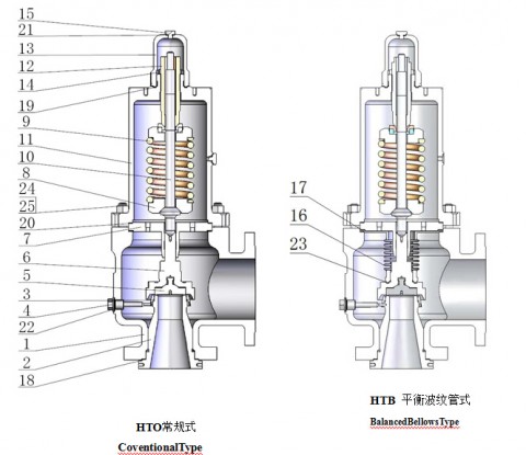
Conventional safety relief valve -The spring housing is vented to the discharge side, hence operational characteristics are directly affected by changes in the backpressure to the valve.
Balanced safety relief valve -A balanced valve incorporates a means of minimising the effect of backpressure on the operational characteristics of the valve.
Pilot operated pressure relief valve -The major relieving device is combined with, and is controlled by, a self-actuated auxiliary pressure relief device.
Power-actuated safety relief valve - A pressure relief valve in which the major pressure relieving device is combined with, and controlled by, a device requiring an external source of energy.
Standard safety valve - A valve which, following opening, reaches the degree of lift necessary for the mass flowrate to be discharged within a pressure rise of not more than 10%. (The valve is characterised by a pop type action and is sometimes known as high lift).
Full lift (Vollhub) safety valve -A safety valve which, after commencement of lift, opens rapidly within a 5% pressure rise up to the full lift as limited by the design. The amount of lift up to the rapid opening (proportional range) shall not be more than 20%.
Direct loaded safety valve -A safety valve in which the opening force underneath the valve disc is opposed by a closing force such as a spring or a weight.
Proportional safety valve - A safety valve which opens more or less steadily in relation to the increase in pressure. Sudden opening within a 10% lift range will not occur without pressure increase. Following opening within a pressure of not more than 10%, these safety valves achieve the lift necessary for the mass flow to be discharged.
Diaphragm safety valve -A direct loaded safety valve wherein linear moving and rotating elements and springs are protected against the effects of the fluid by a diaphragm
Bellows safety valve - A direct loaded safety valve wherein sliding and (partially or fully) rotating elements and springs are protected against the effects of the fluids by a bellows. The bellows may be of such a design that it compensates for influences of backpressure.
Controlled safety valve - Consists of a main valve and a control device. It also includes direct acting safety valves with supplementary loading in which, until the set pressure is reached, an additional force increases the closing force.
Safety valve - A safety valve which automatically, without the assistance of any energy other than that of the fluid concerned, discharges a quantity of the fluid so as to prevent a predetermined safe pressure being exceeded, and which is designed to re-close and prevent further flow of fluid after normal pressure conditions of service have been restored. Note; the valve can be characterised either by pop action (rapid opening) or by opening in proportion (not necessarily linear) to the increase in pressure over the set pressure.
Direct loaded safety valve -A safety valve in which the loading due to the fluid pressure underneath the valve disc is opposed only by a direct mechanical loading device such as a weight, lever and weight, or a spring.
Assisted safety valve -A safety valve which by means of a powered assistance mechanism, may additionally be lifted at a pressure lower than the set pressure and will, even in the event of a failure of the assistance mechanism, comply with all the requirements for safety valves given in the standard.
Supplementary loaded safety valve - A safety valve that has, until the pressure at the inlet to the safety valve reaches the set pressure, an additional force, which increases the sealing force.
Note; this additional force (supplementary load), which may be provided by means of an extraneous power source, is reliably released when the pressure at the inlet of the safety valve reaches the set pressure. The amount of supplementary loading is so arranged that if such supplementary loading is not released, the safety valve will attain its certified discharge capacity at a pressure not greater than 1.1 times the maximum allowable pressure of the equipment to be protected.
Pilot operated safety valve -A safety valve, the operation of which is initiated and controlled by the fluid discharged from a pilot valve, which is itself, a direct loaded safety valve subject to the requirement of the standard.
The common characteristic shared between the definitions of conventional safety valves in the different standards, is that their operational characteristics are affected by any backpressure in the discharge system. It is important to note that the total backpressure is generated from two components; superimposed backpressure and the built-up backpressure:
Subsequently, in a conventional safety valve, only the superimposed backpressure will affect the opening characteristic and set value, but the combined backpressure will alter the blowdown characteristic and re-seat value.
The ASME/ANSI standard makes the further classification that conventional valves have a spring housing that is vented to the discharge side of the valve. If the spring housing is vented to the atmosphere, any superimposed backpressure will still affect the operational characteristics. Thiscan be seen from Figure 9.2.1, which shows schematic diagrams of valves whose spring housings are vented to the discharge side of the valve and to the atmosphere.
By considering the forces acting on the disc (with area AD), it can be seen that the required opening force (equivalent to the product of inlet pressure (PV) and the nozzle area (AN)) is the sum of the spring force (FS) and the force due to the backpressure (PB) acting on the top and bottom of the disc. In the case of a spring housing vented to the discharge side of the valve (an ASME conventional safety relief valve, see Figure 9.2.1 (a)), the required opening force is:
In both cases, if a significant superimposed backpressure exists, its effects on the set pressure need to be considered when designing a safety valve system.
Once the valve starts to open, the effects of built-up backpressure also have to be taken into account. For a conventional safety valve with the spring housing vented to the discharge side of the valve, see Figure 9.2.1 (a), the effect of built-up backpressure can be determined by considering Equation 9.2.1 and by noting that once the valve starts to open, the inlet pressure is the sum of the set pressure, PS, and the overpressure, PO.
Balanced safety valves are those that incorporate a means of eliminating the effects of backpressure. There are two basic designs that can be used to achieve this:
Although there are several variations of the piston valve, they generally consist of a piston type disc whose movement is constrained by a vented guide. The area of the top face of the piston, AP, and the nozzle seat area, AN, are designed to be equal. This means that the effective area of both the top and bottom surfaces of the disc exposed to the backpressure are equal, and therefore any additional forces are balanced. In addition, the spring bonnet is vented such that the top face of the piston is subjected to atmospheric pressure, as shown in Figure 9.2.2.
The bellows arrangement prevents backpressure acting on the upper side of the disc within the area of the bellows. The disc area extending beyond the bellows and the opposing disc area are equal, and so the forces acting on the disc are balanced, and the backpressure has little effect on the valve opening pressure.
Bellows failure is an important concern when using a bellows balanced safety valve, as this may affect the set pressure and capacity of the valve. It is important, therefore, that there is some mechanism for detecting any uncharacteristic fluid flow through the bellows vents. In addition, some bellows balanced safety valves include an auxiliary piston that is used to overcome the effects of backpressure in the case of bellows failure. This type of safety valve is usually only used on critical applications in the oil and petrochemical industries.
Since balanced pressure relief valves are typically more expensive than their unbalanced counterparts, they are commonly only used where high pressure manifolds are unavoidable, or in critical applications where a very precise set pressure or blowdown is required.
This type of safety valve uses the flowing medium itself, through a pilot valve, to apply the closing force on the safety valve disc. The pilot valve is itself a small safety valve.
The diaphragm type is typically only available for low pressure applications and it produces a proportional type action, characteristic of relief valves used in liquid systems. They are therefore of little use in steam systems, consequently, they will not be considered in this text.
The piston type valve consists of a main valve, which uses a piston shaped closing device (or obturator), and an external pilot valve. Figure 9.2.4 shows a diagram of a typical piston type, pilot operated safety valve.
The piston and seating arrangement incorporated in the main valve is designed so that the bottom area of the piston, exposed to the inlet fluid, is less than the area of the top of the piston. As both ends of the piston are exposed to the fluid at the same pressure, this means that under normal system operating conditions, the closing force, resulting from the larger top area, is greater than the inlet force. The resultant downward force therefore holds the piston firmly on its seat.
If the inlet pressure were to rise, the net closing force on the piston also increases, ensuring that a tight shut-off is continually maintained. However, when the inlet pressure reaches the set pressure, the pilot valve will pop open to release the fluid pressure above the piston. With much less fluid pressure acting on the upper surface of the piston, the inlet pressure generates a net upwards force and the piston will leave its seat. This causes the main valve to pop open, allowing the process fluid to be discharged.
When the inlet pressure has been sufficiently reduced, the pilot valve will reclose, preventing the further release of fluid from the top of the piston, thereby re-establishing the net downward force, and causing the piston to reseat.
Pilot operated safety valves offer good overpressure and blowdown performance (a blowdown of 2% is attainable). For this reason, they are used where a narrow margin is required between the set pressure and the system operating pressure. Pilot operated valves are also available in much larger sizes, making them the preferred type of safety valve for larger capacities.
One of the main concerns with pilot operated safety valves is that the small bore, pilot connecting pipes are susceptible to blockage by foreign matter, or due to the collection of condensate in these pipes. This can lead to the failure of the valve, either in the open or closed position, depending on where the blockage occurs.
The terms full lift, high lift and low lift refer to the amount of travel the disc undergoes as it moves from its closed position to the position required to produce the certified discharge capacity, and how this affects the discharge capacity of the valve.
A full lift safety valve is one in which the disc lifts sufficiently, so that the curtain area no longer influences the discharge area. The discharge area, and therefore the capacity of the valve are subsequently determined by the bore area. This occurs when the disc lifts a distance of at least a quarter of the bore diameter. A full lift conventional safety valve is often the best choice for general steam applications.
The disc of a high lift safety valve lifts a distance of at least 1/12th of the bore diameter. This means that the curtain area, and ultimately the position of the disc, determines the discharge area. The discharge capacities of high lift valves tend to be significantly lower than those of full lift valves, and for a given discharge capacity, it is usually possible to select a full lift valve that has a nominal size several times smaller than a corresponding high lift valve, which usually incurs cost advantages.Furthermore, high lift valves tend to be used on compressible fluids where their action is more proportional.
In low lift valves, the disc only lifts a distance of 1/24th of the bore diameter. The discharge area is determined entirely by the position of the disc, and since the disc only lifts a small amount, the capacities tend to be much lower than those of full or high lift valves.
Except when safety valves are discharging, the only parts that are wetted by the process fluid are the inlet tract (nozzle) and the disc. Since safety valves operate infrequently under normal conditions, all other components can be manufactured from standard materials for most applications. There are however several exceptions, in which case, special materials have to be used, these include:
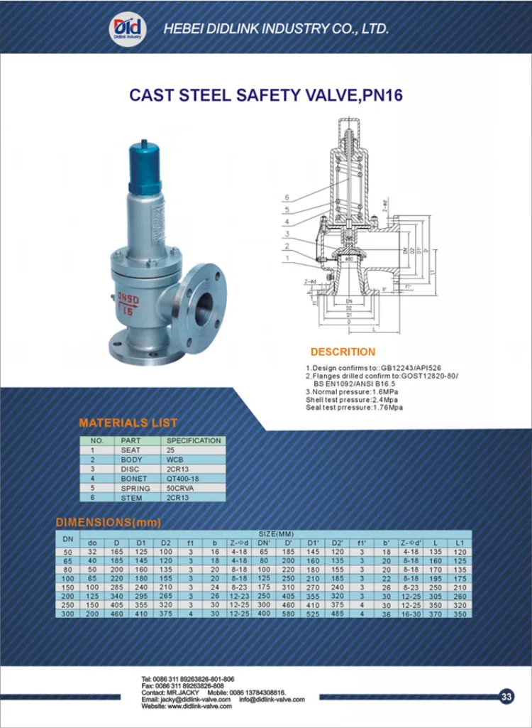
Cast steel -Commonly used on higher pressure valves (up to 40 bar g). Process type valves are usually made from a cast steel body with an austenitic full nozzle type construction.
For all safety valves, it is important that moving parts, particularly the spindle and guides are made from materials that will not easily degrade or corrode. As seats and discs are constantly in contact with the process fluid, they must be able to resist the effects of erosion and corrosion.
The spring is a critical element of the safety valve and must provide reliable performance within the required parameters. Standard safety valves will typically use carbon steel for moderate temperatures. Tungsten steel is used for higher temperature, non-corrosive applications, and stainless steel is used for corrosive or clean steam duty. For sour gas and high temperature applications, often special materials such as monel, hastelloy and ‘inconel’ are used.
Standard safety valves are generally fitted with an easing lever, which enables the valve to be lifted manually in order to ensure that it is operational at pressures in excess of 75% of set pressure. This is usually done as part of routine safety checks, or during maintenance to prevent seizing. The fitting of a lever is usually a requirement of national standards and insurance companies for steam and hot water applications. For example, the ASME Boiler and Pressure Vessel Code states that pressure relief valves must be fitted with a lever if they are to be used on air, water over 60°C, and steam.
A test gag (Figure 9.2.7) may be used to prevent the valve from opening at the set pressure during hydraulic testing when commissioning a system. Once tested, the gag screw is removed and replaced with a short blanking plug before the valve is placed in service.
The amount of fluid depends on the particular design of safety valve. If emission of this fluid into the atmosphere is acceptable, the spring housing may be vented to the atmosphere – an open bonnet. This is usually advantageous when the safety valve is used on high temperature fluids or for boiler applications as, otherwise, high temperatures can relax the spring, altering the set pressure of the valve. However, using an open bonnet exposes the valve spring and internals to environmental conditions, which can lead to damage and corrosion of the spring.
When the fluid must be completely contained by the safety valve (and the discharge system), it is necessary to use a closed bonnet, which is not vented to the atmosphere. This type of spring enclosure is almost universally used for small screwed valves and, it is becoming increasingly common on many valve ranges since, particularly on steam, discharge of the fluid could be hazardous to personnel.
Some safety valves, most commonly those used for water applications, incorporate a flexible diaphragm or bellows to isolate the safety valve spring and upper chamber from the process fluid, (see Figure 9.2.9).
Industry leading pressure and safety relief valve designs with over 140 years of technical and application expertise providing custom engineered solutions for O&G, Refining, Chemical, Petrochemical, Process and Power applications. Our designs meet global and local codes and standards (API 526; ASME Section I, IV & VIII; EN ISO 4126; PED & more). Gain insight into the performance of your pressure relief valves with wireless monitoring.

The primary purpose of a safety valve is to protect life, property and the environment. Safety valves are designed to open and release excess pressure from vessels or equipment and then close again.
The function of safety valves differs depending on the load or main type of the valve. The main types of safety valves are spring-loaded, weight-loaded and controlled safety valves.
Regardless of the type or load, safety valves are set to a specific set pressure at which the medium is discharged in a controlled manner, thus preventing overpressure of the equipment. In dependence of several parameters such as the contained medium, the set pressure is individual for each safety application.

Relief valves are designed to open at a preset pressure (or temperature) level and relieve the system when it has exceeded the desired level. The valve"s relief of elevated liquid, gas, or steam pressures prevents damage to the system. We offer a wide selection of relief valves for any application.

Many electronic, pneumatic and hydraulic systems exist today to control fluid system variables, such as pressure, temperature and flow. Each of these systems requires a power source of some type, such as electricity or compressed air in order to operate. A pressure Relief Valve must be capable of operating at all times, especially during a period of power failure when system controls are nonfunctional. The sole source of power for the pressure Relief Valve, therefore, is the process fluid.
Once a condition occurs that causes the pressure in a system or vessel to increase to a dangerous level, the pressure Relief Valve may be the only device remaining to prevent a catastrophic failure. Since reliability is directly related to the complexity of the device, it is important that the design of the pressure Relief Valve be as simple as possible.
The pressure Relief Valve must open at a predetermined set pressure, flow a rated capacity at a specified overpressure, and close when the system pressure has returned to a safe level. Pressure Relief Valves must be designed with materials compatible with many process fluids from simple air and water to the most corrosive media. They must also be designed to operate in a consistently smooth and stable manner on a variety of fluids and fluid phases.
The basic spring loaded pressure Relief Valve has been developed to meet the need for a simple, reliable, system actuated device to provide overpressure protection.
The Valve consists of a Valve inlet or nozzle mounted on the pressurized system, a disc held against the nozzle to prevent flow under normal system operating conditions, a spring to hold the disc closed, and a body/Bonnet to contain the operating elements. The spring load is adjustable to vary the pressure at which the Valve will open.
When a pressure Relief Valve begins to lift, the spring force increases. Thus system pressure must increase if lift is to continue. For this reason pressure Relief Valves are allowed an overpressure allowance to reach full lift. This allowable overpressure is generally 10% for Valves on unfired systems. This margin is relatively small and some means must be provided to assist in the lift effort.
Most pressure Relief Valves, therefore, have a secondary control chamber or huddling chamber to enhance lift. As the disc begins to lift, fluid enters the control chamber exposing a larger area of the disc to system pressure.
This causes an incremental change in force which overcompensates for the increase in spring force and causes the Valve to open at a rapid rate. At the same time, the direction of the fluid flow is reversed and the momentum effect resulting from the change in flow direction further enhances lift. These effects combine to allow the Valve to achieve maximum lift and maximum flow within the allowable overpressure limits. Because of the larger disc area exposed to system pressure after the Valve achieves lift, the Valve will not close until system pressure has been reduced to some level below the set pressure. The design of the control chamber determines where the closing point will occur.
A safety Valve is a pressure Relief Valve actuated by inlet static pressure and characterized by rapid opening or pop action. (It is normally used for steam and air services.)
A low-lift safety Valve is a safety Valve in which the disc lifts automatically such that the actual discharge area is determined by the position of the disc.
A full-lift safety Valve is a safety Valve in which the disc lifts automatically such that the actual discharge area is not determined by the position of the disc.
A Relief Valve is a pressure relief device actuated by inlet static pressure having a gradual lift generally proportional to the increase in pressure over opening pressure. It may be provided with an enclosed spring housing suitable for closed discharge system application and is primarily used for liquid service.
A safety Relief Valve is a pressure Relief Valve characterized by rapid opening or pop action, or by opening in proportion to the increase in pressure over the opening pressure, depending on the application and may be used either for liquid or compressible fluid.
A conventional safety Relief Valve is a pressure Relief Valve which has its spring housing vented to the discharge side of the Valve. The operational characteristics (opening pressure, closing pressure, and relieving capacity) are directly affected by changes of the back pressure on the Valve.
A balanced safety Relief Valve is a pressure Relief Valve which incorporates means of minimizing the effect of back pressure on the operational characteristics (opening pressure, closing pressure, and relieving capacity).
A pilotoperated pressure Relief Valve is a pressure Relief Valve in which the major relieving device is combined with and is controlled by a self-actuated auxiliary pressure Relief Valve.
A poweractuated pressure Relief Valve is a pressure Relief Valve in which the major relieving device is combined with and controlled by a device requiring an external source of energy.
A temperature-actuated pressure Relief Valve is a pressure Relief Valve which may be actuated by external or internal temperature or by pressure on the inlet side.
A vacuum Relief Valve is a pressure relief device designed to admit fluid to prevent an excessive internal vacuum; it is designed to reclose and prevent further flow of fluid after normal conditions have been restored.
Many Codes and Standards are published throughout the world which address the design and application of pressure Relief Valves. The most widely used and recognized of these is the ASME Boiler and Pressure Vessel Code, commonly called the ASME Code.
is the calculated mass flow from an orifice having a cross sectional area equal to the flow area of the safety Valve without regard to flow losses of the Valve.
the pressure at which a Valve is set on a test rig using a test fluid at ambient temperature. This test pressure includes corrections for service conditions e.g. backpressure or high temperatures.
is the value of increasing static inlet pressure of a pressure Relief Valve at which there is a measurable lift, or at which the discharge becomes continuous as determined by seeing, feeling or hearing.
Because cleanliness is essential to the satisfactory operation and tightness of a safety Valve, precautions should be taken during storage to keep out all foreign materials. Inlet and outlet protectors should remain in place until the Valve is ready to be installed in the system. Take care to keep the Valve inlet absolutely clean. It is recommended that the Valve be stored indoors in the original shipping container away from dirt and other forms of contamination.
Safety Valves must be handled carefully and never subjected to shocks. Rough handling may alter the pressure setting, deform Valve parts and adversely affect seat tightness and Valve performance.
When it is necessary to use a hoist, the chain or sling should be placed around the Valve body and Bonnet in a manner that will insure that the Valve is in a vertical position to facilitate installation.
Many Valves are damaged when first placed in service because of failure to clean the connection properly when installed. Before installation, flange faces or threaded connections on both the Valve inlet and the vessel and/or line on which the Valve is mounted must be thoroughly cleaned of all dirt and foreign material.
Because foreign materials that pass into and through safety Valves can damage the Valve, the systems on which the Valves are tested and finally installed must also be inspected and cleaned. New systems in particular are prone to contain foreign objects that inadvertently get trapped during construction and will destroy the seating surface when the Valve opens. The system should be thoroughly cleaned before the safety Valve is installed.
The gaskets used must be dimensionally correct for the specific flanges. The inside diameters must fully clear the safety Valve inlet and outlet openings so that the gasket does not restrict flow.
For flanged Valves, draw down all connection studs or bolts evenly to avoid possible distortion of the Valve body. For threaded Valves, do not apply a wrench to the Valve body. Use the hex flats provided on the inlet bushing.
Safety Valves are intended to open and close within a narrow pressure range. Valve installations require accurate design both as to inlet and discharge piping. Refer to International, National and Industry Standards for guidelines.
The Valve should be mounted vertically in an upright position either directly on a nozzle from the pressure vessel or on a short connection fitting that provides a direct, unobstructed flow between the vessel and the Valve. Installing a safety Valve in other than this recommended position will adversely affect its operation.
Discharge piping should be simple and direct. A "broken" connection near the Valve outlet is preferred wherever possible. All discharge piping should be run as direct as is practicable to the point of final release for disposal. The Valve must discharge to a safe disposal area. Discharge piping must be drained properly to prevent the accumulation of liquids on the downstream side of the safety Valve.
The weight of the discharge piping should be carried by a separate support and be properly braced to withstand reactive thrust forces when the Valve relieves. The Valve should also be supported to withstand any swaying or system vibrations.
If the Valve is discharging into a pressurized system be sure the Valve is a "balanced" design. Pressure on the discharge of an "unbalanced" design will adversely affect the Valve performance and set pressure.
The Bonnets of balanced bellows safety Valves must always be vented to ensure proper functioning of the Valve and to provide a telltale in the event of a bellows failure. Do not plug these open vents. When the fluid is flammable, toxic or corrosive, the Bonnet vent should be piped to a safe location.
It is important to remember that a pressure Relief Valve is a safety device employed to protect pressure vessels or systems from catastrophic failure. With this in mind, the application of pressure Relief Valves should be assigned only to fully trained personnel and be in strict compliance with rules provided by the governing codes and standards.

Dante Valve recommends the use of a Drip Pan Elbow in conjunction with a steam service safety valve. Drip Pan Elbows can prevent injury and damage to people, equipment or supplies located near the safety valve or discharge piping. When attached to a safety valve outlet, the Drip Pan Elbow collects, removes and returns condensate to safe areas, and isolates the valve from discharge piping stresses. This keeps the safety valve from filling with water.
Drip Pan Elbows also help improve the performance and longevity of the safety valve by alleviating axial loads, preventing defective operations and shut-off. Drip Pan Elbows are compatible with all ASME safety valves and are easily installed on female NPT or flanged outlets.
Dante Valve offers Drip Pan Elbows featuring consistently high quality workmanship and materials. We stock all sizes 3/4″ through 10″ for immediate delivery.


 8613371530291