
boiler safety valve drawing quotation

The main purpose of a safety valve is to prevent the pressure in a system to exceed the certification pressure. Above certification pressure, no one can guaranty the systems safety - and especially for a steam system with very hot gas with huge amount of latent heat, the consequences can be dramatically.
The size of the safety valve depends primarily on the maximum boiler output and the operation pressure of the system. The safety valve shall as minimum have the evacuation capacity of all the vapor the boiler can produce running at full power at working (or certification) pressure.
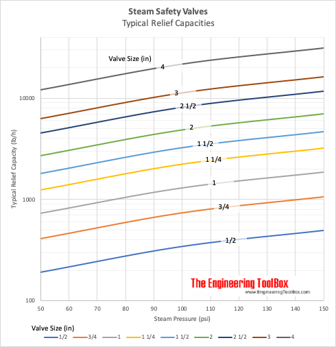
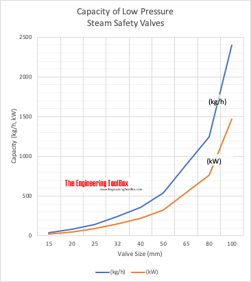
The table below can be used to select a typical safety valve based on boiler output. Before final design, always consult the manufactures documentation.
Note! The table above is based on low pressure steam of 100 kN/m2 (1 bar)or 15 psiin imperial units. Latent heat of saturated steam is 2201 kJ/kg (945 Btu/lb). 1 N/m2 = 1 Pa = 1.4504 x 10⁻⁴ lb/in2 (psi) = 10-5 bar For higher pressure, steam is compressed and require less volume - required size of the valve reduced
Above certification pressure no one can guaranty the systems safety - and especially for a steam system with a very hot gas with a huge amount of latent heat the consequence with a failure can be dramatically.
The size of a safety valve depends primarily on the maximum boiler output and the operation pressure of the system. The safety valve must as minimum have the evacuation capacity of all the vapor the boiler can produce running at full power at the working (or certification) pressure. for a higher pressure the steam is compressed and requires less volume and the size of the valve can be reduced
The tables below can be used to select a typical safety valve in a high pressure system. Before the final design - always consult manufacturing documentation.

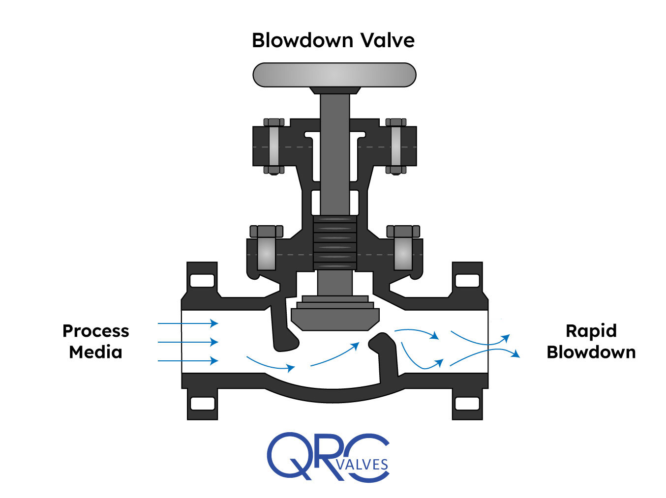
A blowdown valve’s main function is to control a continuous or intermittent flow of steam or fluid under high differential pressure. When installed in a system, they drain solid contaminants from the fluid. In this article, you will learn the working principle of a blowdown valve, review a blowdown valve diagram, and its use in boiler and compressor applications.
In industry, blowdown valves often attach to equipment where water is the working fluid. Usually, this water contains suspended solid impurities. As mechanisms such as vaporization or drafting occur in the system, the concentration of undissolved solids increases and hampers system performance. How? Some of these deposits may accumulate and form blockages that disrupt the flow. Also, the solids could deposit on the surface of the equipment and impact heat transfer. This reduces the efficiency of heat exchangers and designed cooling measures. Thus, blowdown valves along drain lines allow for the removal of these contaminants.
It is a common practice to use two blowdown valves in series. One acts as the seal valve, while the other is the main blowdown valve. Customarily, the seal valve opens first when draining, and closes last. However, to minimize erosion of the valve disk faces and seats, both may open simultaneously and rapidly.
In addition, care should be taken to avoid trapping scale and rust particles within the valve by briefly reopening it, after it has been shut. Especially if there was resistance when closing it initially. One important parameter in the operation of blowdown valves is the blowdown percentage. It refers to the ratio of the quantity of blowdown water (Vblowdown) to that of the feedwater (Vfeed) as the formula below shows.
The classification of blowdown valves depends on either the valve location or working interval. Generally, blowdown valves are installed at the surface or the bottom of the equipment, depending on the speed of solid impurities precipitation. Also, the valve may operate continuously or intermittently. Usually, surface blowdown valves operate in steady state, while bottom blowdown valves work intermittently.
This is suitable for applications where the rate of solid impurities precipitation is relatively slower. For a simple design of this type of valve, a pipe inserts near the surface of the water level. Then, water, along with impurities, goes through the pipe continuously as the valve is normally in the open position.
On the other hand, a more sophisticated design uses a swivel joint with a short length of pipe suspended on a float. Thus, it removes oil floating on the water surface. Typically, surface blowdown valves find use in equipment where a significant amount of vaporization exists. This is because as vaporization occurs, the contaminants, precipitate and remain on the water surface. Also, the outlet of these valves often feeds into a flash tank and provides heating for heat exchangers.
As the name implies, this type of blowdown valves installs at the bottom of the equipment. They are opened periodically to enable the evacuation of accumulated solid impurities and sludge. Unlike the surface blowdown valve, this type does not operate in a steady state. This is because prolonged opening decreases the water level quickly, thereby risking a shutdown of the equipment. A basic requirement of this valve is to provide tight shut-off even after repetitive blowdown operations. Also, the drainpipe diameter should be large enough so that the slug does not clog and block the flow.
The diagram above is that of a manually operated blowdown valve. Of importance, the orifice maintains fluid velocity below levels that could damage the trim. Also, the stem mates to the orifice for proper control, while the open yoke enables the operator to see the position of the plunger in the valve body. A long stroke length of the stem enables the prevention of water hammer, which occurs if the valve is opened or closed too quickly. At the exit, the angle of the orifice is intentionally made divergent, to minimize downstream piping erosion and noise.
Blowdown valves are common in boiler and compressor systems. In compressors, they serve to depressurize the gas in the system at critical times such as shutdown, restart, or in the case of an emergency. In boilers, they see more frequent use, where there could be both bottom blowdown valves, and a surface valve, in some cases.
Generally, in boilers, blowdown valves remove both suspended solids and sludge from the surface and bottom respectively. As a result, it prevents the foaming at the water surface which leads to unstable water levels and excessive passing on of liquid in the steam. When blowdown water leaves a boiler, it does so at high temperatures, creating a safety concern. For example, a boiler working at 100 psig typically discharges around 338 ℉. Thus, engineers must ensure controlled discharge occurs into a flash tank prior to disposal into drainage. Or, engineers may repurpose the heat elsewhere within the facility, perhaps to increase feedwater temperature.
A boiler valve kit is a must-have for any homeowner with a boiler system. This brass valve kit features a vent safety valve that helps to protect your home from dangerous gas build-up. The included instructions make installation easy, and the durable brass construction ensures lasting performance. Keep your family safe with this essential boiler valve kit.
9. When the calibrated pressure is reached, the valve opens automatically and discharges the atmosphere to protect the whole system from safe caused by overpressure
10. This brass boiler valve kit is perfect for any steam-powered project. The kit includes a pressure gauge, safety valve, and two shut-off valves. The pressure gauge helps you monitor the pressure in your boiler, the safety valve keeps your boiler from exploding, and the shut-off valves let you turn off the steam supply without having to drain the boiler.
This brass boiler valve kit is perfect for any steam-related projects you may have. It includes a durable boiler and vent safety valve to keep your project safe and functional. The included instructions make it easy to install this kit in no time. This boiler valve kit is the perfect addition to your tool collection with its high-quality construction and affordable price. This brass boiler valve kit is ideal for any steam-based appliance. The kit includes a boiler valve, vent safety valve, and all the necessary fittings for a quick and easy installation. The included vent safety valve helps to ensure safe operation by releasing excess pressure in the event of a malfunction. This kit is ideal for use with any boiler, including cast iron, steel, or copper boilers.
Vent safety valves are required for all direct-fired appliances; this kit includes everything you need to install one. The boiler valve is brass and has a 1/2-inch pipe thread fitting that can be connected to the vent pipe. It also features an adjustable pressure relief valve with a gauge, protecting your home from high-pressure steam or air from the system. This kit comes with two elbows (1 in., two in.), four nipples (3/4 in., 1/8 in., 3/8 in.), three straight fittings (5/16 inches), and five pipe connectors (3 ways).
This boiler kit includes a brass pressure relief valve with an air vent, which is required by law. It also has a 1/2″ discharge elbow and two unions connecting the pipe inlet to your water heater. The safety valves are designed to prevent excess pressure from building up inside the tank, which can cause dangerous boil-overs or even potential explosions. This kit is excellent for homeowners with existing water heaters without this equipment installed.
In the latter half of the 19th century explosions of steam boilers were commonplace. As a consequence of this, a company was formed in Manchester with the objective of reducing the number of explosions by subjecting steam boilers to independent examination. This company was, in fact, the beginning of today’s Safety Federation (SAFed), the body whose approval is required for boiler controls and fittings in the UK.
After a comparatively short period, only eight out of the 11 000 boilers examined exploded. This compared to 260 steam boiler explosions in boilers not examined by the scheme. This success led to the Boiler Explosions Act (1882) which included a requirement for a boiler name-plate. An example of a boiler name-plate is shown in Figure 3.7.1.
The serial number and model number uniquely identify the boiler and are used when ordering spares from the manufacturer and in the main boiler log book.
In Europe, matters relating to the suitability of safety valves for steam boilers are governed by the European standard EN 12953. In the US and some other parts of the world, such matters are covered by ASME standards.
The total discharge capacity of the safety valve(s) must be at least equal to the ‘from and at 100°C’ capacity of the boiler. If the ‘from and at’ evaporation is used to size the safety valve, the safety valve capacity will always be higher than the actual maximum evaporative boiler capacity.
The discharge pipework from the safety valve must be unobstructed and drained at the base to prevent the accumulation of condensate. It is good practice to ensure that the discharge pipework is kept as short as possible with the minimum number of bends, so that the allowable backpressure indicated by the valve manufacturer is not exceeded.
It will be quite normal for the internal diameter of the discharge pipework to be more than the internal diameter of the safety valve outlet connection, but under no circumstances should it be less.
A steam boiler must be fitted with a stop valve (also known as a crown valve) which isolates the steam boiler and its pressure from the process or plant. It is generally an angle pattern globe valve of the screw-down variety. Figure 3.7.3 shows a typical stop valve of this type.
In the past, these valves have often been manufactured from cast iron, with steel and bronze being used for higher pressure applications. In the UK, BS 2790 (eventually to be replaced with EN 12953) states that cast iron valves are no longer permitted for this application on steam boilers. Nodular or spheroidal graphite (SG) iron should not be confused with grey cast iron as it has mechanical properties approaching those of steel. For this reason many boilermakers use SG iron valves as standard.
The stop valve is not designed as a throttling valve, and should be fully open or closed. It should always be opened slowly to prevent any sudden rise in downstream pressure and associated waterhammer, and to help restrict the fall in boiler pressure and any possible associated priming.
To comply with UK regulations, the valve should be of the ‘rising handwheel’ type. This allows the boiler operator to easily see the valve position, even from floor level. The valve shown is fitted with an indicator that makes this even easier for the operator.
On multi-boiler applications an additional isolating valve should be fitted, in series with the crown valve. At least one of these valves should be lockable in the closed position. The additional valve is generally a globe valve of the screw-down, non-return type which prevents one boiler pressurising another. Alternatively, it is possible to use a screw-down valve, with a disc check valve sandwiched between the flanges of the crown valve and itself.
The feedwater check valve (as shown in Figures 3.7.4 and 3.7.5) is installed in the boiler feedwater line between the feedpump and boiler. A boiler feed stop valve is fitted at the boiler shell.
The check valve includes a spring equivalent to the head of water in the elevated feedtank when there is no pressure in the boiler. This prevents the boiler being flooded by the static head from the boiler feedtank.
Under normal steaming conditions the check valve operates in a conventional manner to stop return flow from the boiler entering the feedline when the feedpump is not running. When the feedpump is running, its pressure overcomes the spring to feed the boiler as normal.
Because a good seal is required, and the temperatures involved are relatively low (usually less than 100°C) a check valve with a EPDM (Ethylene Propylene) soft seat is generally the best option.
The maintenance of water quality is essential to the safe and efficient operation of a steam boiler. The measurement and control of the various parameters is a complex topic, which is also covered by a number of regulations. It is therefore covered in detail later in this Block. The objective of the next few Sections is simply to identify the fittings to be seen on a boiler.
This controls the amount of Total Dissolved Solids (TDS) in the boiler water, and is sometimes also referred to as ‘continuous blowdown’. The boiler connection is typically DN15 or DN20. The system may be manual or automatic. Whatever system is used, the TDS in a sample of boiler water is compared with a set point; if the TDS level is too high, a quantity of boiler water is released to be replaced by feedwater with a much lower TDS level. This has the effect of diluting the water in the boiler, and reducing the TDS level.
This ejects the sludge or sediment from the bottom of the boiler. The control is a large (usually DN25 to DN50) key operated valve. This valve might normally be opened for a period of about 5 seconds, once per shift.
Figure 3.7.7 illustrates a key operated manual bottom blowdown valve whereas Figure 3.7.8 illustrates an automated bottom blowdown valve and its typical position in a blowdown system.
Pressure gauges are connected to the steam space of the boiler and usually have a ring type siphon tube which fills with condensed steam and protects the dial mechanism from high temperatures.
All steam boilers are fitted with at least one water level indicator, but those with a rating of 100 kW or more should be fitted with two indicators. The indicators are usually referred to as gauge glasses complying with EN 12953.
A gauge glass shows the current level of water in the boiler, regardless of the boiler’s operating conditions. Gauge glasses should be installed so that their lowest reading will show the water level at 50 mm above the point where overheating will occur. They should also be fitted with a protector around them, but this should not hinder visibility of the water level. Figure 3.7.10 shows a typical gauge glass.
Gauge glasses are prone to damage from a number of sources, such as corrosion from the chemicals in boiler water, and erosion during blowdown, particularly at the steam end. Any sign of corrosion or erosion indicates that a new glass is required.
If the water passages are choked an artificially high water level may be observed due to steam condensing in the glass. After testing, the glass will tend to remain empty unless the water level in the boiler is higher than the top connection, in which case water might flow into the glass from this connection.
Gauge glass levels must be treated with the utmost respect, as they are the only visual indicator of water level conditions inside the boiler. Any water level perceived as abnormal must be investigated as soon as it is observed, with immediate action taken to shut down the boiler burner if necessary.
The maintenance of the correct water level in a steam boiler is essential to its safe and efficient operation. The methods of sensing the water level, and the subsequent control of water level is a complex topic that is covered by a number of regulations. The following few Sections will provide a brief overview, and the topic will be discussed in much greater detail later.
The function of the level controls or alarms is checked daily using the sequencing purge valves. With the handwheel turned fully anticlockwise the valve is in the ‘normal working’ position and a back seating shuts off the drain connection. The handwheel dial may look similar to that shown in Figure 3.7.12. Some handwheels have no dial, but rely on a mechanism for correct operation.
Slowly move the handwheel further clockwise to full travel. The water connection is shut-off, the drain valve remains open, and the float chamber and steam connections are blown through. The boiler controls should operate as for lowered water level in boiler i.e. pump running and / or audible alarm sounding and burner cut-out. Alternatively if the level control chamber is fitted with a second or extra low water alarm, the boiler should lock-out.
Sequencing purge valves are provided by a number of different manufacturers. Each may differ in operating procedure. It is essential that the manufacturer’s instructions be followed regarding this operation.
Level control systems with sensors (or probes) which fit inside the boiler shell (or steam drum) are also available. These provide a higher degree of safety than those fitted externally. The level alarm systems may also provide a self-checking function on system integrity.
When a boiler is started from cold, the steam space is full of air. This air has no heat value, and will adversely affect steam plant performance due to its effect of blanketing heat exchange surfaces. The air can also give rise to corrosion in the condensate system, if not removed adequately.
The air may be purged from the steam space using a simple cock; normally this would be left open until a pressure of about 0.5 bar is showing on the pressure gauge. An alternative to the cock is a balanced pressure air vent which not only relieves the boiler operator of the task of manually purging air (and hence ensures that it is actually done), it is also much more accurate and will vent gases which may accumulate in the boiler. Typical air vents are shown in Figure 3.7.14.
When a boiler is taken off-line, the steam in the steam space condenses and leaves a vacuum. This vacuum causes pressure to be exerted on the boiler from the outside, and can result in boiler inspection doors leaking, damage to the boiler flat plates and the danger of overfilling a shutdown boiler. To avoid this, a vacuum breaker (see Figure 3.7.14) is required on the boiler shell.
Series 174A Boiler Pressure Relief Valves are used in hot water heating and domestic supply boiler applications to protect against excessive pressures on all types of hot water heating supply boiler equipment. They have a bronze body construction with NPT threaded female inlet and NPT threaded female outlet (drain) connections, non-metallic disc-to-metal seating, stainless steel spring, and test lever. Series 174A resists corrosive water conditions, sticking, and freezing, and it prevents water and sediment from being trapped in the seat. It is designed for emergency safety relief and shall not be used as an operating control. Standard Pressure Setting: 30psi (206.9 kPa). Pressure Range: In 5psi (34.5 kPa) increments from 30 to 150psi (2 to 10 bar) with corresponding high ratings from 650,000 to 14,370,000 BTU/hr.
Relief valves are designed to open at a preset pressure (or temperature) level and relieve the system when it has exceeded the desired level. The valve"s relief of elevated liquid, gas, or steam pressures prevents damage to the system. We offer a wide selection of relief valves for any application.
Dante Valve recommends the use of a Drip Pan Elbow in conjunction with a steam service safety valve. Drip Pan Elbows can prevent injury and damage to people, equipment or supplies located near the safety valve or discharge piping. When attached to a safety valve outlet, the Drip Pan Elbow collects, removes and returns condensate to safe areas, and isolates the valve from discharge piping stresses. This keeps the safety valve from filling with water.
Drip Pan Elbows also help improve the performance and longevity of the safety valve by alleviating axial loads, preventing defective operations and shut-off. Drip Pan Elbows are compatible with all ASME safety valves and are easily installed on female NPT or flanged outlets.
Dante Valve offers Drip Pan Elbows featuring consistently high quality workmanship and materials. We stock all sizes 3/4″ through 10″ for immediate delivery.

Boiler explosions have been responsible for widespread damage to companies throughout the years, and that’s why today’s boilers are equipped with safety valves and/or relief valves. Boiler safety valves are designed to prevent excess pressure, which is usually responsible for those devastating explosions. That said, to ensure that boiler safety valves are working properly and providing adequate protection, they must meet regulatory specifications and require ongoing maintenance and periodic testing. Without these precautions, malfunctioning safety valves may fail, resulting in potentially disastrous consequences.
Boiler safety valves are activated by upstream pressure. If the pressure exceeds a defined threshold, the valve activates and automatically releases pressure. Typically used for gas or vapor service, boiler safety valves pop fully open once a pressure threshold is reached and remain open until the boiler pressure reaches a pre-defined, safe lower pressure.
Boiler relief valves serve the same purpose – automatically lowering boiler pressure – but they function a bit differently than safety valves. A relief valve doesn’t open fully when pressure exceeds a defined threshold; instead, it opens gradually when the pressure threshold is exceeded and closes gradually until the lower, safe threshold is reached. Boiler relief valves are typically used for liquid service.
There are also devices known as “safety relief valves” which have the characteristics of both types discussed above. Safety relief valves can be used for either liquid or gas or vapor service.
Nameplates must be fastened securely and permanently to the safety valve and remain readable throughout the lifespan of the valve, so durability is key.
The National Board of Boiler and Pressure Vessel Inspectors offers guidance and recommendations on boiler and pressure vessel safety rules and regulations. However, most individual states set forth their own rules and regulations, and while they may be similar across states, it’s important to ensure that your boiler safety valves meet all state and local regulatory requirements.
The National Board published NB-131, Recommended Boiler and Pressure Vessel Safety Legislation, and NB-132, Recommended Administrative Boiler and Pressure Vessel Safety Rules and Regulationsin order to provide guidance and encourage the development of crucial safety laws in jurisdictions that currently have no laws in place for the “proper construction, installation, inspection, operation, maintenance, alterations, and repairs” necessary to protect workers and the public from dangerous boiler and pressure vessel explosions that may occur without these safeguards in place.
The American Society of Mechanical Engineers (ASME) governs the code that establishes guidelines and requirements for safety valves. Note that it’s up to plant personnel to familiarize themselves with the requirements and understand which parts of the code apply to specific parts of the plant’s steam systems.
High steam capacity requirements, physical or economic constraints may make the use of a single safety valve impossible. In these cases, using multiple safety valves on the same system is considered an acceptable practice, provided that proper sizing and installation requirements are met – including an appropriately sized vent pipe that accounts for the total steam venting capacity of all valves when open at the same time.
The lowest rating (MAWP or maximum allowable working pressure) should always be used among all safety devices within a system, including boilers, pressure vessels, and equipment piping systems, to determine the safety valve set pressure.
Avoid isolating safety valves from the system, such as by installing intervening shut-off valves located between the steam component or system and the inlet.
Contact the valve supplier immediately for any safety valve with a broken wire seal, as this indicates that the valve is unsafe for use. Safety valves are sealed and certified in order to prevent tampering that can prevent proper function.
Avoid attaching vent discharge piping directly to a safety valve, which may place unnecessary weight and additional stress on the valve, altering the set pressure.
A safety valve is a valve that acts as a fail-safe. An example of safety valve is a pressure relief valve (PRV), which automatically releases a substance from a boiler, pressure vessel, or other system, when the pressure or temperature exceeds preset limits. Pilot-operated relief valves are a specialized type of pressure safety valve. A leak tight, lower cost, single emergency use option would be a rupture disk.
Safety valves were first developed for use on steam boilers during the Industrial Revolution. Early boilers operating without them were prone to explosion unless carefully operated.
Vacuum safety valves (or combined pressure/vacuum safety valves) are used to prevent a tank from collapsing while it is being emptied, or when cold rinse water is used after hot CIP (clean-in-place) or SIP (sterilization-in-place) procedures. When sizing a vacuum safety valve, the calculation method is not defined in any norm, particularly in the hot CIP / cold water scenario, but some manufacturers
The earliest and simplest safety valve was used on a 1679 steam digester and utilized a weight to retain the steam pressure (this design is still commonly used on pressure cookers); however, these were easily tampered with or accidentally released. On the Stockton and Darlington Railway, the safety valve tended to go off when the engine hit a bump in the track. A valve less sensitive to sudden accelerations used a spring to contain the steam pressure, but these (based on a Salter spring balance) could still be screwed down to increase the pressure beyond design limits. This dangerous practice was sometimes used to marginally increase the performance of a steam engine. In 1856, John Ramsbottom invented a tamper-proof spring safety valve that became universal on railways. The Ramsbottom valve consisted of two plug-type valves connected to each other by a spring-laden pivoting arm, with one valve element on either side of the pivot. Any adjustment made to one of valves in an attempt to increase its operating pressure would cause the other valve to be lifted off its seat, regardless of how the adjustment was attempted. The pivot point on the arm was not symmetrically between the valves, so any tightening of the spring would cause one of the valves to lift. Only by removing and disassembling the entire valve assembly could its operating pressure be adjusted, making impromptu "tying down" of the valve by locomotive crews in search of more power impossible. The pivoting arm was commonly extended into a handle shape and fed back into the locomotive cab, allowing crews to "rock" both valves off their seats to confirm they were set and operating correctly.
Safety valves also evolved to protect equipment such as pressure vessels (fired or not) and heat exchangers. The term safety valve should be limited to compressible fluid applications (gas, vapour, or steam).
For liquid-packed vessels, thermal relief valves are generally characterized by the relatively small size of the valve necessary to provide protection from excess pressure caused by thermal expansion. In this case a small valve is adequate because most liquids are nearly incompressible, and so a relatively small amount of fluid discharged through the relief valve will produce a substantial reduction in pressure.
Flow protection is characterized by safety valves that are considerably larger than those mounted for thermal protection. They are generally sized for use in situations where significant quantities of gas or high volumes of liquid must be quickly discharged in order to protect the integrity of the vessel or pipeline. This protection can alternatively be achieved by installing a high integrity pressure protection system (HIPPS).
In the petroleum refining, petrochemical, chemical manufacturing, natural gas processing, power generation, food, drinks, cosmetics and pharmaceuticals industries, the term safety valve is associated with the terms pressure relief valve (PRV), pressure safety valve (PSV) and relief valve.
The generic term is Pressure relief valve (PRV) or pressure safety valve (PSV). PRVs and PSVs are not the same thing, despite what many people think; the difference is that PSVs have a manual lever to open the valve in case of emergency.
Relief valve (RV): an automatic system that is actuated by the static pressure in a liquid-filled vessel. It specifically opens proportionally with increasing pressure
Pilot-operated safety relief valve (POSRV): an automatic system that relieves on remote command from a pilot, to which the static pressure (from equipment to protect) is connected
Low pressure safety valve (LPSV): an automatic system that relieves static pressure on a gas. Used when the difference between the vessel pressure and the ambient atmospheric pressure is small.
Vacuum pressure safety valve (VPSV): an automatic system that relieves static pressure on a gas. Used when the pressure difference between the vessel pressure and the ambient pressure is small, negative and near to atmospheric pressure.
Low and vacuum pressure safety valve (LVPSV): an automatic system that relieves static pressure on a gas. Used when the pressure difference is small, negative or positive and near to atmospheric pressure.
In most countries, industries are legally required to protect pressure vessels and other equipment by using relief valves. Also, in most countries, equipment design codes such as those provided by the ASME, API and other organizations like ISO (ISO 4126) must be complied with. These codes include design standards for relief valves and schedules for periodic inspection and testing after valves have been removed by the company engineer.
Today, the food, drinks, cosmetics, pharmaceuticals and fine chemicals industries call for hygienic safety valves, fully drainable and Cleanable-In-Place. Most are made of stainless steel; the hygienic norms are mainly 3A in the USA and EHEDG in Europe.
The first safety valve was invented by Denis Papin for his steam digester, an early pressure cooker rather than an engine.steelyard" lever a smaller weight was required, also the pressure could easily be regulated by sliding the same weight back and forth along the lever arm. Papin retained the same design for his 1707 steam pump.Greenwich in 1803, one of Trevithick"s high-pressure stationary engines exploded when the boy trained to operate the engine left it to catch eels in the river, without first releasing the safety valve from its working load.
Although the lever safety valve was convenient, it was too sensitive to the motion of a steam locomotive. Early steam locomotives therefore used a simpler arrangement of weights stacked directly upon the valve. This required a smaller valve area, so as to keep the weight manageable, which sometimes proved inadequate to vent the pressure of an unattended boiler, leading to explosions. An even greater hazard was the ease with which such a valve could be tied down, so as to increase the pressure and thus power of the engine, at further risk of explosion.
Although deadweight safety valves had a short lifetime on steam locomotives, they remained in use on stationary boilers for as long as steam power remained.
Weighted valves were sensitive to bouncing from the rough riding of early locomotives. One solution was to use a lightweight spring rather than a weight. This was the invention of Timothy Hackworth on his leaf springs.
These direct-acting spring valves could be adjusted by tightening the nuts retaining the spring. To avoid tampering, they were often shrouded in tall brass casings which also vented the steam away from the locomotive crew.
The Salter coil spring spring balance for weighing, was first made in Britain by around 1770.spring steels to make a powerful but compact spring in one piece. Once again by using the lever mechanism, such a spring balance could be applied to the considerable force of a boiler safety valve.
The spring balance valve also acted as a pressure gauge. This was useful as previous pressure gauges were unwieldy mercury manometers and the Bourdon gauge had yet to be invented.
Paired valves were often adjusted to slightly different pressures too, a small valve as a control measure and the lockable valve made larger and permanently set to a higher pressure, as a safeguard.Sinclair for the Eastern Counties Railway in 1859, had the valve spring with pressure scale behind the dome, facing the cab, and the locked valve ahead of the dome, out of reach of interference.
In 1855, John Ramsbottom, later locomotive superintendent of the LNWR, described a new form of safety valve intended to improve reliability and especially to be tamper-resistant. A pair of plug valves were used, held down by a common spring-loaded lever between them with a single central spring. This lever was characteristically extended rearwards, often reaching into the cab on early locomotives. Rather than discouraging the use of the spring lever by the fireman, Ramsbottom"s valve encouraged this. Rocking the lever freed up the valves alternately and checked that neither was sticking in its seat.
A drawback to the Ramsbottom type was its complexity. Poor maintenance or mis-assembly of the linkage between the spring and the valves could lead to a valve that no longer opened correctly under pressure. The valves could be held against their seats and fail to open or, even worse, to allow the valve to open but insufficiently to vent steam at an adequate rate and so not being an obvious and noticeable fault.Rhymney Railway, even though the boiler was almost new, at only eight months old.
Naylor valves were introduced around 1866. A bellcrank arrangement reduced the strain (percentage extension) of the spring, thus maintaining a more constant force.L&Y & NER.
All of the preceding safety valve designs opened gradually and had a tendency to leak a "feather" of steam as they approached "blowing-off", even though this was below the pressure. When they opened they also did so partially at first and didn"t vent steam quickly until the boiler was well over pressure.
The quick-opening "pop" valve was a solution to this. Their construction was simple: the existing circular plug valve was changed to an inverted "top hat" shape, with an enlarged upper diameter. They fitted into a stepped seat of two matching diameters. When closed, the steam pressure acted only on the crown of the top hat, and was balanced by the spring force. Once the valve opened a little, steam could pass the lower seat and began to act on the larger brim. This greater area overwhelmed the spring force and the valve flew completely open with a "pop". Escaping steam on this larger diameter also held the valve open until pressure had dropped below that at which it originally opened, providing hysteresis.
These valves coincided with a change in firing behaviour. Rather than demonstrating their virility by always showing a feather at the valve, firemen now tried to avoid noisy blowing off, especially around stations or under the large roof of a major station. This was mostly at the behest of stationmasters, but firemen also realised that any blowing off through a pop valve wasted several pounds of boiler pressure; estimated at 20 psi lost and 16 lbs or more of shovelled coal.
Pop valves derived from Adams"s patent design of 1873, with an extended lip. R. L. Ross"s valves were patented in 1902 and 1904. They were more popular in America at first, but widespread from the 1920s on.
Although showy polished brass covers over safety valves had been a feature of steam locomotives since Stephenson"s day, the only railway to maintain this tradition into the era of pop valves was the GWR, with their distinctive tapered brass safety valve bonnets and copper-capped chimneys.
Developments in high-pressure water-tube boilers for marine use placed more demands on safety valves. Valves of greater capacity were required, to vent safely the high steam-generating capacity of these large boilers.Naylor valve) became more critical.distilled feedwater and also a scouring of the valve seats, leading to wear.
High-lift safety valves are direct-loaded spring types, although the spring does not bear directly on the valve, but on a guide-rod valve stem. The valve is beneath the base of the stem, the spring rests on a flange some height above this. The increased space between the valve itself and the spring seat allows the valve to lift higher, further clear of the seat. This gives a steam flow through the valve equivalent to a valve one and a half or twice as large (depending on detail design).
The Cockburn Improved High Lift design has similar features to the Ross pop type. The exhaust steam is partially trapped on its way out and acts on the base of the spring seat, increasing the lift force on the valve and holding the valve further open.
To optimise the flow through a given diameter of valve, the full-bore design is used. This has a servo action, where steam through a narrow control passage is allowed through if it passes a small control valve. This steam is then not exhausted, but is passed to a piston that is used to open the main valve.
There are safety valves known as PSV"s and can be connected to pressure gauges (usually with a 1/2" BSP fitting). These allow a resistance of pressure to be applied to limit the pressure forced on the gauge tube, resulting in prevention of over pressurisation. the matter that has been injected into the gauge, if over pressurised, will be diverted through a pipe in the safety valve, and shall be driven away from the gauge.
There is a wide range of safety valves having many different applications and performance criteria in different areas. In addition, national standards are set for many kinds of safety valves.
Safety valves are required on water heaters, where they prevent disaster in certain configurations in the event that a thermostat should fail. Such a valve is sometimes referred to as a "T&P valve" (Temperature and Pressure valve). There are still occasional, spectacular failures of older water heaters that lack this equipment. Houses can be leveled by the force of the blast.
Pressure cookers usually have two safety valves to prevent explosions. On older designs, one is a nozzle upon which a weight sits. The other is a sealed rubber grommet which is ejected in a controlled explosion if the first valve gets blocked. On newer generation pressure cookers, if the steam vent gets blocked, a safety spring will eject excess pressure and if that fails, the gasket will expand and release excess pressure downwards between the lid and the pan. Also, newer generation pressure cookers have a safety interlock which locks the lid when internal pressure exceeds atmospheric pressure, to prevent accidents from a sudden release of very hot steam, food and liquid, which would happen if the lid were to be removed when the pan is still slightly pressurised inside (however, the lid will be very hard or impossible to open when the pot is still pressurised).


 8613371530291