
boiler safety valve gagging tool free sample

IMO your question is more suitable for PSV forum http://www.eng-tips.com/threadminder.cfm?pid=1203 . Of course some of us in this forum have experiences in safety valve.
See some hint from some expert whom have done this http://www.eng-tips.com/viewthread.cfm?qid=180240 . Moral of the story, this is a risky job with some uncertainties, be cautious for operator to position themselves when performing this. If your safety valve is open loop, do not position any parts of someones" body in front or near the outlet
Be cautious that you or the commissioning personnel should correspond both safety valves" setting pressure vs the testing pressure. If its gagged (set the screw to prevent it from opening)at X Psi, then the testing pressure is not advisable to exceed 5% of X. this potentially bent the spindle. And if this happened, as per safety regulation the damage parts shall be renewed with UV stamped (read: original) manufacturer parts (if your safety valve manufacturer and your boiler are referring to ASME).

Before attempting to adjust the safety valves of any boiler,its essential to verify the accuracy of the boiler pressure gauge,safety valves must be set at a pressure not exceeding 3% above the approved working pressure each safety valve is adjusted independently.
You will hear a hissing sound, this is the floating condition of the valve and subsequently the valve will lift. if the valve lifts before the set pressure is achieved tighten the compression nut. if the valve fails to lift at the set pressure loosen the compression nut, maintain the boiler pressure constant while adjusting, reduce boiler pressure, remove gagging tool and fit to other valve for setting.
After both valves are set, remove the gagging tool and fire the boiler to maximum capacity. note full flow of waste steam from waste steam pipe. note pressure on gauge, the pressure should not exceed 10% of set pressure. after completion refit caps, cotter, locks and easing gear.

Boiler safety valve setting procedure is given in this article. To make the content easier to understand and also to make reader to understand as how this important activity is done.
As an engineer onboard you will be required to set the safety valve after each boiler survey. It is a process which needs precision and skill also. Let’s check the stepwise details of the procedure you need to follow while setting the valve.
2) Boiler is ready to be fired. Make sure that the steam blow off line after the safety valve, have a drain and it should be unclogged and should have free passage.
7) Screw down the compression nut little bit more than the previous distance. If you don’t have previous reading, then it will require little bit more attempts before you can actually set the valve.
8) Now let’s say you have to set valve at 9 bar. So, raise the pressure slowly. Just before the 9 bar, like 8.8 or 8.9, you will start seeing little bit of steam coming out of the safety valve.
Note: If you safety valve lifts at 10 bar instead of 9, then don’t try to set it down at the same time. Lower the pressure to 7 bar or something and then adjust the compression nut and then again raise the pressure to 9 bar. Otherwise you get all the wrong adjustment.
14) After both valves are set, they usually have some difference like 0.3 bar. This is not intentional and comes due to the fact that precise and similar adjust of both the valves is not same.

There is a wide range of safety valves available to meet the many different applications and performance criteria demanded by different industries. Furthermore, national standards define many varying types of safety valve.
The ASME standard I and ASME standard VIII for boiler and pressure vessel applications and the ASME/ANSI PTC 25.3 standard for safety valves and relief valves provide the following definition. These standards set performance characteristics as well as defining the different types of safety valves that are used:
ASME I valve - A safety relief valve conforming to the requirements of Section I of the ASME pressure vessel code for boiler applications which will open within 3% overpressure and close within 4%. It will usually feature two blowdown rings, and is identified by a National Board ‘V’ stamp.
ASME VIII valve- A safety relief valve conforming to the requirements of Section VIII of the ASME pressure vessel code for pressure vessel applications which will open within 10% overpressure and close within 7%. Identified by a National Board ‘UV’ stamp.
Full bore safety valve - A safety valve having no protrusions in the bore, and wherein the valve lifts to an extent sufficient for the minimum area at any section, at or below the seat, to become the controlling orifice.
Conventional safety relief valve -The spring housing is vented to the discharge side, hence operational characteristics are directly affected by changes in the backpressure to the valve.
Balanced safety relief valve -A balanced valve incorporates a means of minimising the effect of backpressure on the operational characteristics of the valve.
Pilot operated pressure relief valve -The major relieving device is combined with, and is controlled by, a self-actuated auxiliary pressure relief device.
Power-actuated safety relief valve - A pressure relief valve in which the major pressure relieving device is combined with, and controlled by, a device requiring an external source of energy.
Standard safety valve - A valve which, following opening, reaches the degree of lift necessary for the mass flowrate to be discharged within a pressure rise of not more than 10%. (The valve is characterised by a pop type action and is sometimes known as high lift).
Full lift (Vollhub) safety valve -A safety valve which, after commencement of lift, opens rapidly within a 5% pressure rise up to the full lift as limited by the design. The amount of lift up to the rapid opening (proportional range) shall not be more than 20%.
Direct loaded safety valve -A safety valve in which the opening force underneath the valve disc is opposed by a closing force such as a spring or a weight.
Proportional safety valve - A safety valve which opens more or less steadily in relation to the increase in pressure. Sudden opening within a 10% lift range will not occur without pressure increase. Following opening within a pressure of not more than 10%, these safety valves achieve the lift necessary for the mass flow to be discharged.
Diaphragm safety valve -A direct loaded safety valve wherein linear moving and rotating elements and springs are protected against the effects of the fluid by a diaphragm
Bellows safety valve - A direct loaded safety valve wherein sliding and (partially or fully) rotating elements and springs are protected against the effects of the fluids by a bellows. The bellows may be of such a design that it compensates for influences of backpressure.
Controlled safety valve - Consists of a main valve and a control device. It also includes direct acting safety valves with supplementary loading in which, until the set pressure is reached, an additional force increases the closing force.
Safety valve - A safety valve which automatically, without the assistance of any energy other than that of the fluid concerned, discharges a quantity of the fluid so as to prevent a predetermined safe pressure being exceeded, and which is designed to re-close and prevent further flow of fluid after normal pressure conditions of service have been restored. Note; the valve can be characterised either by pop action (rapid opening) or by opening in proportion (not necessarily linear) to the increase in pressure over the set pressure.
Direct loaded safety valve -A safety valve in which the loading due to the fluid pressure underneath the valve disc is opposed only by a direct mechanical loading device such as a weight, lever and weight, or a spring.
Assisted safety valve -A safety valve which by means of a powered assistance mechanism, may additionally be lifted at a pressure lower than the set pressure and will, even in the event of a failure of the assistance mechanism, comply with all the requirements for safety valves given in the standard.
Supplementary loaded safety valve - A safety valve that has, until the pressure at the inlet to the safety valve reaches the set pressure, an additional force, which increases the sealing force.
Note; this additional force (supplementary load), which may be provided by means of an extraneous power source, is reliably released when the pressure at the inlet of the safety valve reaches the set pressure. The amount of supplementary loading is so arranged that if such supplementary loading is not released, the safety valve will attain its certified discharge capacity at a pressure not greater than 1.1 times the maximum allowable pressure of the equipment to be protected.
Pilot operated safety valve -A safety valve, the operation of which is initiated and controlled by the fluid discharged from a pilot valve, which is itself, a direct loaded safety valve subject to the requirement of the standard.
The common characteristic shared between the definitions of conventional safety valves in the different standards, is that their operational characteristics are affected by any backpressure in the discharge system. It is important to note that the total backpressure is generated from two components; superimposed backpressure and the built-up backpressure:
Subsequently, in a conventional safety valve, only the superimposed backpressure will affect the opening characteristic and set value, but the combined backpressure will alter the blowdown characteristic and re-seat value.
The ASME/ANSI standard makes the further classification that conventional valves have a spring housing that is vented to the discharge side of the valve. If the spring housing is vented to the atmosphere, any superimposed backpressure will still affect the operational characteristics. Thiscan be seen from Figure 9.2.1, which shows schematic diagrams of valves whose spring housings are vented to the discharge side of the valve and to the atmosphere.
By considering the forces acting on the disc (with area AD), it can be seen that the required opening force (equivalent to the product of inlet pressure (PV) and the nozzle area (AN)) is the sum of the spring force (FS) and the force due to the backpressure (PB) acting on the top and bottom of the disc. In the case of a spring housing vented to the discharge side of the valve (an ASME conventional safety relief valve, see Figure 9.2.1 (a)), the required opening force is:
In both cases, if a significant superimposed backpressure exists, its effects on the set pressure need to be considered when designing a safety valve system.
Once the valve starts to open, the effects of built-up backpressure also have to be taken into account. For a conventional safety valve with the spring housing vented to the discharge side of the valve, see Figure 9.2.1 (a), the effect of built-up backpressure can be determined by considering Equation 9.2.1 and by noting that once the valve starts to open, the inlet pressure is the sum of the set pressure, PS, and the overpressure, PO.
Balanced safety valves are those that incorporate a means of eliminating the effects of backpressure. There are two basic designs that can be used to achieve this:
Although there are several variations of the piston valve, they generally consist of a piston type disc whose movement is constrained by a vented guide. The area of the top face of the piston, AP, and the nozzle seat area, AN, are designed to be equal. This means that the effective area of both the top and bottom surfaces of the disc exposed to the backpressure are equal, and therefore any additional forces are balanced. In addition, the spring bonnet is vented such that the top face of the piston is subjected to atmospheric pressure, as shown in Figure 9.2.2.
The bellows arrangement prevents backpressure acting on the upper side of the disc within the area of the bellows. The disc area extending beyond the bellows and the opposing disc area are equal, and so the forces acting on the disc are balanced, and the backpressure has little effect on the valve opening pressure.
Bellows failure is an important concern when using a bellows balanced safety valve, as this may affect the set pressure and capacity of the valve. It is important, therefore, that there is some mechanism for detecting any uncharacteristic fluid flow through the bellows vents. In addition, some bellows balanced safety valves include an auxiliary piston that is used to overcome the effects of backpressure in the case of bellows failure. This type of safety valve is usually only used on critical applications in the oil and petrochemical industries.
Since balanced pressure relief valves are typically more expensive than their unbalanced counterparts, they are commonly only used where high pressure manifolds are unavoidable, or in critical applications where a very precise set pressure or blowdown is required.
This type of safety valve uses the flowing medium itself, through a pilot valve, to apply the closing force on the safety valve disc. The pilot valve is itself a small safety valve.
The diaphragm type is typically only available for low pressure applications and it produces a proportional type action, characteristic of relief valves used in liquid systems. They are therefore of little use in steam systems, consequently, they will not be considered in this text.
The piston type valve consists of a main valve, which uses a piston shaped closing device (or obturator), and an external pilot valve. Figure 9.2.4 shows a diagram of a typical piston type, pilot operated safety valve.
The piston and seating arrangement incorporated in the main valve is designed so that the bottom area of the piston, exposed to the inlet fluid, is less than the area of the top of the piston. As both ends of the piston are exposed to the fluid at the same pressure, this means that under normal system operating conditions, the closing force, resulting from the larger top area, is greater than the inlet force. The resultant downward force therefore holds the piston firmly on its seat.
If the inlet pressure were to rise, the net closing force on the piston also increases, ensuring that a tight shut-off is continually maintained. However, when the inlet pressure reaches the set pressure, the pilot valve will pop open to release the fluid pressure above the piston. With much less fluid pressure acting on the upper surface of the piston, the inlet pressure generates a net upwards force and the piston will leave its seat. This causes the main valve to pop open, allowing the process fluid to be discharged.
When the inlet pressure has been sufficiently reduced, the pilot valve will reclose, preventing the further release of fluid from the top of the piston, thereby re-establishing the net downward force, and causing the piston to reseat.
Pilot operated safety valves offer good overpressure and blowdown performance (a blowdown of 2% is attainable). For this reason, they are used where a narrow margin is required between the set pressure and the system operating pressure. Pilot operated valves are also available in much larger sizes, making them the preferred type of safety valve for larger capacities.
One of the main concerns with pilot operated safety valves is that the small bore, pilot connecting pipes are susceptible to blockage by foreign matter, or due to the collection of condensate in these pipes. This can lead to the failure of the valve, either in the open or closed position, depending on where the blockage occurs.
The terms full lift, high lift and low lift refer to the amount of travel the disc undergoes as it moves from its closed position to the position required to produce the certified discharge capacity, and how this affects the discharge capacity of the valve.
A full lift safety valve is one in which the disc lifts sufficiently, so that the curtain area no longer influences the discharge area. The discharge area, and therefore the capacity of the valve are subsequently determined by the bore area. This occurs when the disc lifts a distance of at least a quarter of the bore diameter. A full lift conventional safety valve is often the best choice for general steam applications.
The disc of a high lift safety valve lifts a distance of at least 1/12th of the bore diameter. This means that the curtain area, and ultimately the position of the disc, determines the discharge area. The discharge capacities of high lift valves tend to be significantly lower than those of full lift valves, and for a given discharge capacity, it is usually possible to select a full lift valve that has a nominal size several times smaller than a corresponding high lift valve, which usually incurs cost advantages.Furthermore, high lift valves tend to be used on compressible fluids where their action is more proportional.
In low lift valves, the disc only lifts a distance of 1/24th of the bore diameter. The discharge area is determined entirely by the position of the disc, and since the disc only lifts a small amount, the capacities tend to be much lower than those of full or high lift valves.
Except when safety valves are discharging, the only parts that are wetted by the process fluid are the inlet tract (nozzle) and the disc. Since safety valves operate infrequently under normal conditions, all other components can be manufactured from standard materials for most applications. There are however several exceptions, in which case, special materials have to be used, these include:
Cast steel -Commonly used on higher pressure valves (up to 40 bar g). Process type valves are usually made from a cast steel body with an austenitic full nozzle type construction.
For all safety valves, it is important that moving parts, particularly the spindle and guides are made from materials that will not easily degrade or corrode. As seats and discs are constantly in contact with the process fluid, they must be able to resist the effects of erosion and corrosion.
The spring is a critical element of the safety valve and must provide reliable performance within the required parameters. Standard safety valves will typically use carbon steel for moderate temperatures. Tungsten steel is used for higher temperature, non-corrosive applications, and stainless steel is used for corrosive or clean steam duty. For sour gas and high temperature applications, often special materials such as monel, hastelloy and ‘inconel’ are used.
Standard safety valves are generally fitted with an easing lever, which enables the valve to be lifted manually in order to ensure that it is operational at pressures in excess of 75% of set pressure. This is usually done as part of routine safety checks, or during maintenance to prevent seizing. The fitting of a lever is usually a requirement of national standards and insurance companies for steam and hot water applications. For example, the ASME Boiler and Pressure Vessel Code states that pressure relief valves must be fitted with a lever if they are to be used on air, water over 60°C, and steam.
A test gag (Figure 9.2.7) may be used to prevent the valve from opening at the set pressure during hydraulic testing when commissioning a system. Once tested, the gag screw is removed and replaced with a short blanking plug before the valve is placed in service.
The amount of fluid depends on the particular design of safety valve. If emission of this fluid into the atmosphere is acceptable, the spring housing may be vented to the atmosphere – an open bonnet. This is usually advantageous when the safety valve is used on high temperature fluids or for boiler applications as, otherwise, high temperatures can relax the spring, altering the set pressure of the valve. However, using an open bonnet exposes the valve spring and internals to environmental conditions, which can lead to damage and corrosion of the spring.
When the fluid must be completely contained by the safety valve (and the discharge system), it is necessary to use a closed bonnet, which is not vented to the atmosphere. This type of spring enclosure is almost universally used for small screwed valves and, it is becoming increasingly common on many valve ranges since, particularly on steam, discharge of the fluid could be hazardous to personnel.
Some safety valves, most commonly those used for water applications, incorporate a flexible diaphragm or bellows to isolate the safety valve spring and upper chamber from the process fluid, (see Figure 9.2.9).
Four types of commonly used Boiler Safety Valves are: Dead weight safety valve, Spring loaded safety valve, Lever safety valve and High steam and low water safety valve. The choice of a particular type of safety valve for a boiler depends on the type of the boiler and its safe working pressure.Learn More
Choose from our selection of boiler safety valves, including over 60 products in a wide range of styles and sizes. In stock and ready to ship.Learn More
5/5 · Boiler systems have safety valves to protect them from over pressure operation due to any reason. These safety valves are provided in drum, superheater and reheater inlet andLearn More
For steam boilers, a small overpressure is required, usually 3% or 5%. For most other applications, 10% overpressure is required, but according to API 520, for special applications such as fire protection, larger valves with overpressures of 20% are allowed. For most types of safety valve, air or gas setting is permissible. A speciallyLearn More
1. Safety valve pressure setting can be done from high to low pressure or vice-versa. 2. Take necessary personal safety valve precaution and arrange tools i.e. gagging tool and master gauge. 3. Slowly raise the boiler pressure and blow off the safety valve manually few times for thermal expansion and to reduce the thermal stress on the valves. 4.Learn More
A second type of pressure relief valve which offers advantages in selected applications is the valves on boiler external piping, safety relief valves on.Learn More
Safety valve can be classified according to the amount that the valve will lift against the spring pressure. · Ordinary Spring Loaded · High Lift · Improved High Lift · Full Lift · Full Bore Relay The area of the bore of the valve governs the theoretical maximum amount of steam that can pass through a valve of any design.Learn More
There are three main components of a safety valve: disc, nozzle, and spring. The total capacity of the safety valve must be more than the maximum flow capacity (MFC) of the safety valve in case steam valves fail to open. Most steam boilers connect two safety valves in it, but it may require a third safety valve if it does not exceed the MFC.Learn More
By increasing the operating pressure of the system beyond the specified, the safety valve (safety valve) stabilizes the pressure by discharging a volume of fluid out of the system. It is important that the safety valves perform their function under any circumstances and prevent Increase system pressure. Category: Boiler accessories. Description.Learn More
The safety valve for the boiler compensates for the expansion. arising when heating water. Thus, the work of the indirect water heater and the boiler are closely related. For this type of water heaters, it is required to choose a suitable safety valve. All the characteristics we need are listed in the technical data sheet of the device, soLearn More
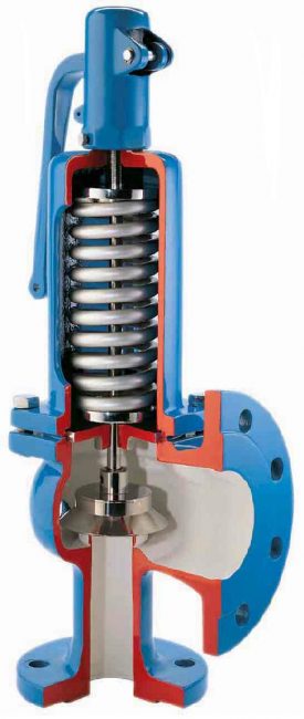
The most commonly used safety valve is spring loaded safety valve. Below shows the constructions and working principle of a spring loaded safety valve.Learn More
2022/9/8 · FBC operation. Engineering of FBC boilers. Caustic gouging. Boiler water management. Boiler inspection -shut down. Alkali boil out. A coverage on safety valve. Student Portal. Behavioural Training Modules.Learn More
Safety valves are generally located on the steam drum of the boiler and open automatically when the inlet-side pressure of the valves exceedsLearn More
Safety Valve Which Automatically Discharges Steam and Safety Valves Fast Response 100% Customer Satisfaction at best prices in India. HP Valve Offers Types Of Air Safety Valve,Learn More
Safety Valves - A safety valve is a valve that acts as a fail-safe in a thermal-hydraulics plant. An example of safety valve is a pressure relief valve (PRV), which automatically releases a substance from a boiler, pressure vessel, or other system, when the pressure or temperature exceeds preset limits. | PowerPoint PPT presentation | free to viewLearn More
The function of safety valves differs depending on the load or main type of the valve. The main types of safety valves are spring-loaded, weight-loaded andLearn More
How There are three main parts to the safety valve: nozzle, disc, and spring. Pressurized steam enters the valve through the nozzle and is then threaded to the boiler. The disc is the lid to the nozzle, which opens or closes depending on the pressure coming from the boiler. The spring is the pressure controller.Learn More
There are many Different Types of valves used in the industry like Gate Valve Globe Valve Y - Type Globe Valve Ball Valve Plug Valve Diaphragm Valves Reducing Valves Pinch Valve Butterfly Valve Needle Valve Check Valve Relief & safety valve Solenoid Valve Globe ValvesLearn More
Types of Safety Valves: · Dead weight safety valve. · Spring loaded safety valve · Lever loaded safety valve · High steam and low water safety valve · Spring loadedLearn More
Four types of safety valve that we can deal with are; Deadweight safety valve (i.e. Weight lies on top of pressure cooker) Lever-type safety valve Spring-loaded safety valve High steam and low water safety valve Steam Stop Valve Function A Steam stop valve has the function to regulate the flow of steam from the boiler to the steam pipe.Learn More
The spring type safety valve must have a device to prevent the screws and nuts from being turned randomly. The static weight safety valve must have a device to prevent the heavy piece from flying off. The globe valve on the inlet pipe of impulse type safety valves must be fully opened, locked or sealed. Reliable air and power sources should beLearn More
Spring loaded mechanically operating safety valve valves are used in boiler drum and super heater outlet. In addition to spring loaded safety valve ElectromaticLearn More
High performance safety valve for the protection of large boilers and The nozzle uses an austenitic stainless steel stabilised with Niobium,Learn More
ENTRADE Boiler Valves: We are valve specialists and have a wide range of valve types in particular Crown valves and Boiler Water level gauges. Safety valve - Wikipedia, the free encyclopedia. The two general types of protection encountered in industry are thermal such a spring balance could be applied to the considerable force of a boilerLearn More
There are also devices known as "safety relief valves" which have the characteristics of both types discussed above. Safety relief valves can be used for either liquid or gas or vapor service. Boiler Safety Valve Nameplate Requirements Safety valves require nameplates that contain important information about the device, including: CapacityLearn More
Dead weight safety valve,; Spring loaded safety valve,; Lever safety valve and; High steam and low water safety valve. The choice of a particular type of safetyLearn More
Marine Boiler [Part-1], Safety Valve. Safety valve are fitted to protect the boiler from over pressure. Type of boiler safety valve, marine auxiliary boiler and exhaust gas boiler setting of safety valve, accumulation pressure test, boiler safety valve set pressure, boiler safety valve working pressure , material used in construction of safetyLearn More
A safety valve is a valve mechanism for the automatic release of steam from the boiler of a steam locomotive, which helps prevent from a steam locomotive from exploding. Safety valves were first used on steam locomotives during the industrial revolution in the late-1800"s. Early boilers without them were prone to accidental explosion. They are equipped on just aboutLearn More
Safety Valve - This device is typically used for steam or vapor service. It operates automatically with a full-opening pop action and recloses when the pressure drops to a value consistent with the blowdown requirements prescribed by the applicable governing code or standard. Relief Valve - This device is typically used for liquid service.Learn More


 8613371530291