
boiler safety valve leaking factory
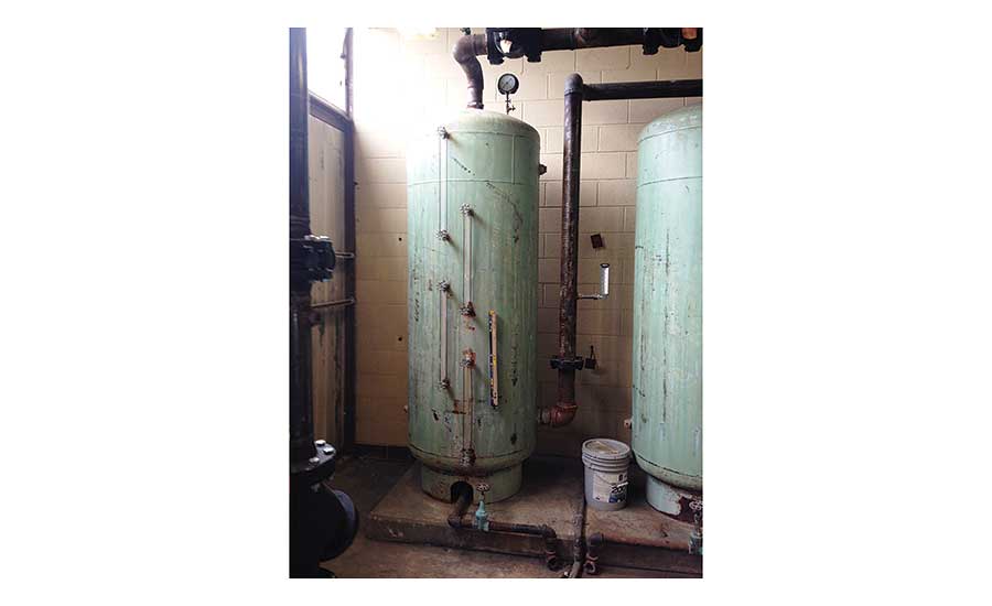
A common sight in a hydronic boiler room is water dripping from the discharge pipe of the boiler relief valve. While it may appear to be inconsequential, it could cause extensive damage to the heating system.
Some boiler rooms have a bucket under the relief valve discharge pipe to mask the problem. The following are some suggestions if you would like to resolve the problem.
Leaking water from a sealed hydronic system can reduce the life of the system by introducing untreated makeup water containing oxygen and solids to the system. The oxygen can attack and pit the boiler and piping, causing corrosion and leaks.
The solids can affect the efficiency and safety of the system. Solids form scale on the hottest surfaces in the boiler lowering the heat transfer ability and efficiency of the system. A leaking relief valve can allow solids to form on the seat of the relief valve increasing the rate of the leak.
A worse situation occurs when the solids form on the spring side of the relief valve as it could alter the opening pressure. A relief valve was a contributing factor in a fatal boiler accident as scale formed on the relief valve, prohibiting it from opening properly.
The relief valve, rated for 30 psig, was tested after the accident and did not open until the pressure reached 1,500 psig. Diagnosing the cause of the leaking relief valve is time-consuming and sometimes frustrating. I like to explain this to the customer to prepare them when the diagnosis and repair may take more than one visit.
The first thing I check is the system pressure. Most hydronic boilers have a gauge called a tridicator, or PTA (pressure, temperature, altitude) gauge. How much pressure do we need for the system? Each pound of system pressure will raise water 2.3 feet. The way to calculate how much pressure you need is to determine the height of the tallest radiator and divide the height by 2.3.
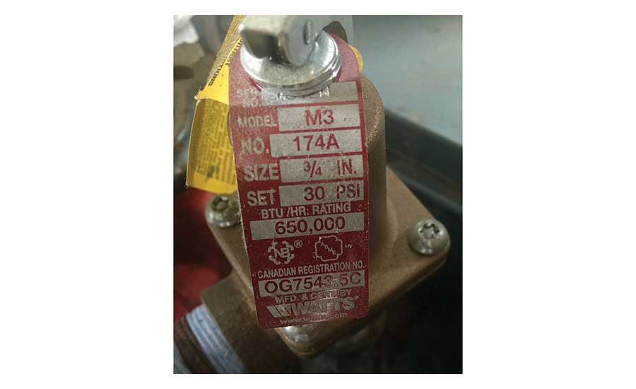
The next step is to verify the pressure rating of the relief valve. The pressure rating of the relief valve should be at least 10 psig higher than the operating pressure of the system but less than the maximum allowable working pressure (MAWP) of the boiler. Many hydronic boilers are shipped with a 30 psig relief valve from the factory. In this example, the relief valve should be at 40 psig or higher. If the system pressure is 30 psig and the relief valve, rated for 40 psig, is leaking, the relief valve is most likely defective.
Another troubleshooting task I perform is watching the tridicator (or PTA gauge) while the boiler is firing and heating the water. When water is heated from 65° F to 180°, the water volume expands by 3%. If the pressure gauge starts creeping up as the water heats, I would suspect a flooded compression tank or plugged piping to the compression tank.
In some instances, it may take several days for the pressure to build and open the relief valve and these are the most difficult to troubleshoot. The first place I would look is the compression tank. If the tank is flooded, there are a couple of reasons.
The most common causes are leaking gauge glass fittings above the water line of the tank, excessive system pressure, undersized tank, or the tank has a leak above the water line. If the system has been operating correctly for years, I would be hesitant to believe the tank is undersized.
A pinhole leak on top of the tank may be impossible to find and one of the ways to test the integrity of the tank is to valve off the water feeder to the system and check the tank in a few days to see if it flooded. If the tank is flooded, you might have to replace the tank.
Another culprit that can cause the pressure to rise and open the relief valve is if the boiler has an indirect water which uses the boiler water to heat the domestic water using a water to water heat exchanger. A leaking heat exchanger could allow the higher city water pressure to enter the space heating side and increase the system pressure. To test this idea, shut the valves from the domestic water side and see if the pressure still rises.
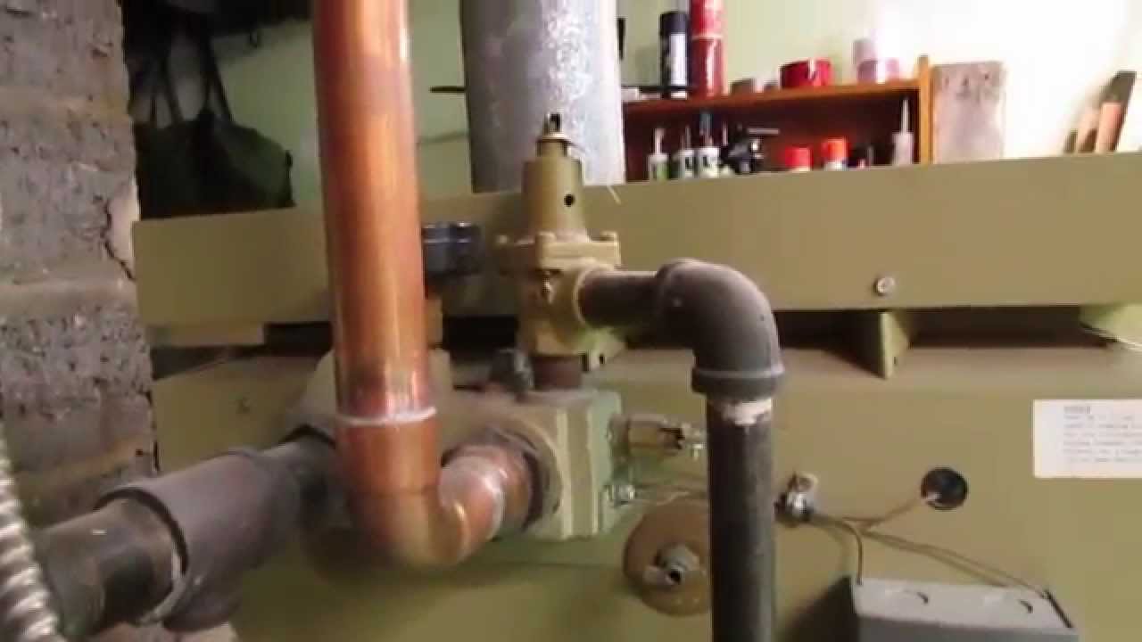
The last item to check is the pressure-reducing valve (PRV). This is a brass valve with an adjustment screw. Some models have a quick-fill feature, which allows you to pull a lever and quickly fill the system. A stethoscope is sometimes used to trouble shoot the PRV to detect if water is leaking through the valve.
Another way to test for leaking is to feel the downstream pipe and see if it is cold. In many instances, the water is fed slowly and difficult to detect. Another way to test to see if the PRV is leaking through is to shut off the valves on the feed water pipe and see if the pressure still rises. If it does, I will suspect the piping to the compression tank is restricted or the tank is flooded. If the pressure does not rise, it could be the pressure reducing valve.
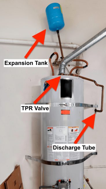
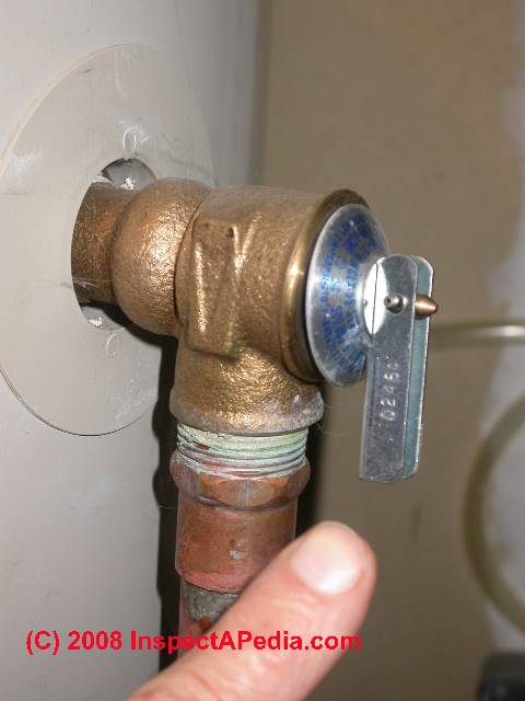
The water heater is known for its high heat and high pressure. The water heater temperature-pressure relief valve (TPR Valve), protects us from this high heat and pressure. So what is the TPR valve, why does it leak, and what should you do about it?
The TPR valve, also called, a pressure relief valve is a specialized valve at your water heater. This valve is typically on the top or side of your water heater.
The valve functions by releasing water if your water heater becomes too pressurized. Since heated water expands, the water heater can become a ticking time bomb if we were to continually build pressure in your water heater.
As seen in the featured image, a TPR valve is required to have a discharge pipe/tube. This tube should be aimed straight to the ground and never go up. This is because hot water will come out of the TPR valve as it releases water. Therefore, extremely hot water should discharge to the ground for safety.
Additionally, if a pipe were to go up, water will have to work against gravity to empty. So, it is possible a slow drip of the TPR valve will collect water in the tubing and ultimately rust out the valve rather than empty it to the floor.
Be one nominal size larger than the size of the relief valve outlet, where the relief valve discharge piping is installed with insert fittings. The outlet end of such tubing shall be fastened in place.
However, if you find the relief valve to continue to leak even after replacement, you should contact a plumber for assistance. A licensed plumber will be able to evaluate your system and decide on installing an expansion tank or other solutions.

The safety valve for the boiler is an essential automatic component for the system. Its main role is to prevent the pressure from rising above an excessively dangerous value, which is about 3 bar for normal wall-mounted boilers: if this value is exceeded, the valve acts automatically going to discharge the excess pressure and bringing the system back to ideal operating conditions. In fact, if this device is not working, you could run the risk of having an excessive pressure on the pipe and this could lead to a sudden explosion with all the risks deriving from it both for the health of people who are in the vicinity and for the safety of the system itself.
Sometimes it may happen that the safety valve has persistent and constant dripping and one is led to think that the problem is due to the component itself and to its sub-optimal construction. This, however, is not entirely true and the problems that are downstream are usually different.
As for the first problem, limestone is formed inside the pipes and tends to be transported to the gasket area afterwards, a fundamental element for sealing the safety valve for the boiler. In this position, the limestone is placed under the gasket, not allowing perfect housing and functioning and therefore leading to dripping. The solution for this specific cause is given by cleaning the system which must be carried out with specific products aimed at eliminating this chemical compound.
As seen, therefore, the problems can be manifold and the main method to avoid them is related to the correct maintenance and cleaning of the system, as well as effective loading. All this allows you to save both in terms of time and in terms of costs but, mainly, allows you to increase the safety level of the system.
The safety valves, as previously introduced, may have more or less consistent drips based on various problems that can develop during operation and the only solution, together with the forecast in the design phase, is the maintenance of the systems.
Inspections are usually carried out by trained and experienced personnel who are able to identify even the first signs of a possible failure or loss of functionality. When an anomaly in operation occurs, these valves are sent for repair to authorized centers or by the manufacturers themselves who, knowing the project and the production process, can intervene effectively, eliminating the problem.
If the damage is excessively extensive and it is impossible to guarantee the restoration of the valve, it must be replaced since, being safety components, it can create situations that are even more onerous than dripping.
06/02/2015 Safety valves are necessary for your own protection Protect your system against damages by using a safety valve to be applied to the output of your generator.
06/09/2015 The installation maintenance and the boiler safety valve Limiting the limy deposits improves the boiler safety valve"s life, as well as the one of the system.
06/04/2022 Safety valves and block valves In addition to the safety valves, in the catalog you can also find block valves that foresee uncontrolled leaks

Pressure relief valves ensure efficiency and safety in many chemical, oil, and gas plants, but they’re susceptible to leaks. If a pressure relief valve is leaking, systems can become overpressurized and even fail, especially if the valve isn’t addressed or repaired quickly.
When you shut down the system, carefully examine the pipelines and the valve itself to determine the cause of the leak. This will help you figure out exactly what you need to do to repair it.
Pressure relief valve leaks usually occur when the valve isn’t properly seated or when the seal is broken or damaged. Leaks can also happen when the pressure relief valve is operating too closely to the set point.
If the valve isn’t completely repaired after your first attempt, you have up to 15 days to perform any additional repairs according to the EPA. If the valve still isn’t fixed, then you can either replace the pressure relief valve or wait until the next shutdown cycle to do more repairs.
When the pressure relief valve has been fixed or replaced, it’s important to take the necessary steps to avoid leaks in the future. To do that, consider implementing a leak detection and repair (LDAR) program for your company.
An LDAR program will help to train workers on everything they need to know about detecting and repairing a leak before system damage can occur. It will also help you monitor valves more efficiently so you can spot leaks faster and spend less money on overall valve repair and maintenance costs.
Valve leakage is a common but troublesome occurrence in industrial facilities. While some valves are expected to have a certain level of leakage, especially as they begin to reach nameplate set pressure, other valve leakage is problematic and can even be dangerous for your facility. If you suspect valve leakage, here are a few reasons why your safety or pressure relief valve may be leaking, how to test the valve, and how to troubleshoot a valve you’ve confirmed is leaking. Four common reasons a pressure relief valve might be leaking include:
Pressure relief and safety relief valves will leak if the valve isn’t fully closed. This is a common problem in industrial settings where environments are often dusty or dirty. If there is any debris in the valve, it can obstruct the valve from fully closing, causing it to leak.
Pressure relief valves age and can begin to deteriorate, especially in factories and facilities where they encounter extreme temperatures and a great deal of wear. Over time, valves can become damaged, which affects their ability to close properly. If there is any damage or excessive wear to the valve seat or seal, leakage is likely.
Another common cause of safety relief valve leakage is when the valve is the wrong size for the project. Whether it’s a loose fit or the wrong fit entirely, a poorly fitting valve won’t be able to function properly, and will often leak.
If you suspect a leaking safety relief valve, or if you would like to complete regular maintenance to prevent valve leakage in the first place, it’s good to know that it is possible to test for a leaking valve. Known as a seat tightness or leakage test, these tests maintain the pressure relief valve’s inlet pressure at a certain percentage of the valve’s set pressure, so the valve technician can assess the valve’s condition.
The AccuTEST inline valve testing system offers a unique feature — the Lift and Hold test — specifically designed to test for leakage. The system performs an automated leakage test according to the operator’s requirements. The operator sets the percent of set pressure and the duration of the test. When the operator starts the test, the AccuTEST system takes over, holding the valve at the appointed percentage of set pressure for the specified duration. While the system holds the valve at pressure, the operator is able to count any bubbles in the valve to assess its condition and determine whether the valve is leaking or not.
When you have confirmed the source of the leak, you can assess whether the valve could be repaired, or if it should be completely replaced. For example, if the valve is the wrong size or if the valve is damaged, it’s best to replace it. If the valve can be cleaned and adjusted to function properly, then repair may be an option.
Once your leaking safety relief valve has been repaired or replaced and is functioning as it should, it’s important to consider implementing regular maintenance and testing. Leaking pressure relief valves can present serious complications for the functionality of your facility. Implementing a regular maintenance and pressure relief valve testing schedule can help you stay in front of concerns like this, ensuring your facility is running efficiently, and at pressure, at all times.
If you are concerned about a leaking safety or pressure relief valve, or are seeking inline valve testing equipment that is capable of performing seat tightness or leakage tests, you might be interested in AccuTEST’s equipment. With exclusive Lift and Hold testing capabilities, AccuTEST inline pressure relief valve testing equipment offers the functionality you need. See how our equipment works in real-time — schedule a live webinar demo today.
The pressure relief valve of your boiler is a very important part of your heating system. This is because it is a safety valve that protects your heating system from building up too much pressure. When that happens, you are faced with leaks or even the possibility of your heating system blowing up. When you notice a leak coming from your boiler pressure relief valve, attend to it immediately. Here are possible causes and solutions to fix such a problem.
Eventually, everything will give in to wear and tear. This safety valve should be checked at least every three months. If you haven’t checked it for quite some time, check it right away because unchecked valves can become rusted and closed.
IMPORTANT:Make sure to turn the power of the boiler off and allow the water to cool for about two hours. Then check the temperature first before you pull the lever.
This pressure reducing valve is designed to allow only 12psi into the boiler. If it is allowing the pressure to reach 30psi or higher, leaks can occur. To check if the fill valve is the problem, turn the boiler off, allow it to cool, drain some of the water until the pressure reaches 10psi. Don’t turn the boiler back on and wait if the gauge starts to go up again. If it does, then the fill valve may be defective.
IMPORTANT:If the fill valve reaches up to 30psi or higher and there are no leaks, shut off your boiler and call a plumber immediately because this is a very dangerous situation.
This part allows water in the boiler to expand. Over time, it becomes logged with water or air starts to leak out of the tank, and when this happens the pressure relief valve will start to leak. Watch the pressure gauge when the boiler is heating, and if the pressure builds during the process, then the tank is most likely the problem and needs to be replaced.
This gauge is required in most area codes, so if you don’t have one, you should have one installed. If your aquastat or its backup (the aquastat relay) is defective, the temperature of your boiler can reach a very high point. This is extremely dangerous and can cause your relief valve to blow off. You must immediately turn off your boiler and call a plumber right away.
Some boilers have a tankless water heater or what is also known as a hot water coil. Sometimes, this coil will develop a pin in it, and this causes pressure to seep into the boiler and leads to leaks in the pressure relief valve. Turn off the water to the coil and check if the pressure stops rising. If it rises with the water off, the hot water coil is the problem.
REMINDER:Because repairing a leak in the relief valve of a boiler involves handling water that can be extremely hot or boiler parts that are sensitive, there is always a risk of endangering yourself or damaging your heating system. So if you are not too experienced with handling such repairs, it is best to call a professional plumber.
It depends. Some of the valves we carry run between $100-$200, as they are suitable for smaller applications. Some industrial settings may need larger or more robust valves, which can run upwards of $1,000 or $2,000.
We recommend that your maximum expected operating pressure will not exceed 90% of the valve’s set pressure. This helps to ensure the valve’s seat will stay tight.
Identifying the process media, or service, of a valve is important to set pressure. If a valve has the correct set pressure but is used on the wrong application, there’s a chance the valve won’t open when needed. This could cause an overpressure event.
No. The valve’s set pressure is measured in gauge pressure, or pounds per square inch gauge (psig), so you don’t have to take altitude into account when selecting your valve.
Back pressure can have complex effects on a valve’s set pressure, capacity, and overall performance. If you know your application will have any type of back pressure, we recommend getting in touch with one of our specialists to verify how it may affect your valve selection or performance.
When you’re shopping on Valves Depot or looking at a valve nameplate, you might see references to ASME Sections I (V stamp), IV (HV stamp), or VIII (UV stamp) in the valve specs. These refer to the ASME (American Society of Mechanical Engineers) Boiler and Pressure Vessel Code (BPVC) standard, a set of guidelines for valve manufacturing.
When you’re installing a smaller valve, preventing damage is as simple as handling the new valve with care. Some parts are fragile. But for larger, heavier valves, during installation, pay close attention to the lever — make sure your lifting straps don’t accidentally wrap around or otherwise conflict with it.
After your initial inspection, schedule maintenance every two to six months. Your maintenance interval will depend on your service conditions and the age of the valve.
Some valve models are required to have a drain hole per the ASME Boiler and Pressure Vessel Code. The drain hole helps prevent condensate from accumulating in the body that could freeze or corrode internal valve parts.
Just because your valve is leaking doesn’t necessarily mean that you need a new valve or repairs — you may need to adjust your operating procedures. Lowering your system pressure, accounting for expected pressure spikes, and regularly calibrating your gauges are a few possible ways to help stop or prevent leakage.

I"m trying to take a trip with my family and need to run my oil boiler for a week or two while I"m gone. I fired it up and every thing worked fine, except when the boiler would reach 170F - 190F the 30psi relief valve would start dripping and then pouring water. I replaced the valve, fired it back up still leaking. I checked the expansion tank which seemed to be water logged and replaced it. I fired it back up still leaking. I replaced the water feed reduction valve to one that was factory set to 12- 15 psi. still leaking. I"m kind of at a loss. I"ve been racking my brain trying to figure what else could cause the pressure trip the valve. I don"t trust the pressure gauge on the boiler it is reads only 12psi, but I"m not sure if I"ve ever seen it move. Any Idea"s???? Great Grand parents, Grand parents and Grand children are anxiously waiting for me to find a fix.

First, turn the filler valve for the heating system fully off. (I never rely on the auto-fill systems at my house- YMMV- you"ll hear the sizzle & bang from low pressure long before it"s a hazard or damaging). Bleed water on the heating system until the pressure is about 12-15psi- note the pressure carefully. Check it again in 24-48 hours. If it"s climbing over time back up to the 35psi level, you have a leak between the potable and heating system side of the hot water coil.
If it"s leaking, rather than replacing the coil, install an indirect-fired tank for the hot water operated as a separate heating system zone, capping the ports to the coil. You can then lower the standby temp on the boiler to save money (which would be considerable, if oil or propane.) It"s safe to use 130F as a low-limit for gas, 140F for oil. Most newer gas boilers can be cold-fired without damage, but some older units might have leakage issues when cold. Some newer oil-boilers can be cold-fired, most older units not, but unless the flue has a stainless liner, cold-firing just for HW heating calls in summer can lead to damaging levels of acidic-exhaust condensation on ceramic-lined flues.
When installing an indirect on an older boiler, it"s worth installing a heat-purging fuel economizer (eg. Intellicon 3250 HW+ ) which minimizes standby loss on the boiler by always parking it at a lower temp at the end of a burn, and taking it to the (programmed) low-limit before firing on during a new call for heat.
A safety valve is a valve that acts as a fail-safe. An example of safety valve is a pressure relief valve (PRV), which automatically releases a substance from a boiler, pressure vessel, or other system, when the pressure or temperature exceeds preset limits. Pilot-operated relief valves are a specialized type of pressure safety valve. A leak tight, lower cost, single emergency use option would be a rupture disk.
Safety valves were first developed for use on steam boilers during the Industrial Revolution. Early boilers operating without them were prone to explosion unless carefully operated.
Vacuum safety valves (or combined pressure/vacuum safety valves) are used to prevent a tank from collapsing while it is being emptied, or when cold rinse water is used after hot CIP (clean-in-place) or SIP (sterilization-in-place) procedures. When sizing a vacuum safety valve, the calculation method is not defined in any norm, particularly in the hot CIP / cold water scenario, but some manufacturers
The earliest and simplest safety valve was used on a 1679 steam digester and utilized a weight to retain the steam pressure (this design is still commonly used on pressure cookers); however, these were easily tampered with or accidentally released. On the Stockton and Darlington Railway, the safety valve tended to go off when the engine hit a bump in the track. A valve less sensitive to sudden accelerations used a spring to contain the steam pressure, but these (based on a Salter spring balance) could still be screwed down to increase the pressure beyond design limits. This dangerous practice was sometimes used to marginally increase the performance of a steam engine. In 1856, John Ramsbottom invented a tamper-proof spring safety valve that became universal on railways. The Ramsbottom valve consisted of two plug-type valves connected to each other by a spring-laden pivoting arm, with one valve element on either side of the pivot. Any adjustment made to one of valves in an attempt to increase its operating pressure would cause the other valve to be lifted off its seat, regardless of how the adjustment was attempted. The pivot point on the arm was not symmetrically between the valves, so any tightening of the spring would cause one of the valves to lift. Only by removing and disassembling the entire valve assembly could its operating pressure be adjusted, making impromptu "tying down" of the valve by locomotive crews in search of more power impossible. The pivoting arm was commonly extended into a handle shape and fed back into the locomotive cab, allowing crews to "rock" both valves off their seats to confirm they were set and operating correctly.
Safety valves also evolved to protect equipment such as pressure vessels (fired or not) and heat exchangers. The term safety valve should be limited to compressible fluid applications (gas, vapour, or steam).
For liquid-packed vessels, thermal relief valves are generally characterized by the relatively small size of the valve necessary to provide protection from excess pressure caused by thermal expansion. In this case a small valve is adequate because most liquids are nearly incompressible, and so a relatively small amount of fluid discharged through the relief valve will produce a substantial reduction in pressure.
Flow protection is characterized by safety valves that are considerably larger than those mounted for thermal protection. They are generally sized for use in situations where significant quantities of gas or high volumes of liquid must be quickly discharged in order to protect the integrity of the vessel or pipeline. This protection can alternatively be achieved by installing a high integrity pressure protection system (HIPPS).
In the petroleum refining, petrochemical, chemical manufacturing, natural gas processing, power generation, food, drinks, cosmetics and pharmaceuticals industries, the term safety valve is associated with the terms pressure relief valve (PRV), pressure safety valve (PSV) and relief valve.
The generic term is Pressure relief valve (PRV) or pressure safety valve (PSV). PRVs and PSVs are not the same thing, despite what many people think; the difference is that PSVs have a manual lever to open the valve in case of emergency.
Relief valve (RV): an automatic system that is actuated by the static pressure in a liquid-filled vessel. It specifically opens proportionally with increasing pressure
Pilot-operated safety relief valve (POSRV): an automatic system that relieves on remote command from a pilot, to which the static pressure (from equipment to protect) is connected
Low pressure safety valve (LPSV): an automatic system that relieves static pressure on a gas. Used when the difference between the vessel pressure and the ambient atmospheric pressure is small.
Vacuum pressure safety valve (VPSV): an automatic system that relieves static pressure on a gas. Used when the pressure difference between the vessel pressure and the ambient pressure is small, negative and near to atmospheric pressure.
Low and vacuum pressure safety valve (LVPSV): an automatic system that relieves static pressure on a gas. Used when the pressure difference is small, negative or positive and near to atmospheric pressure.
In most countries, industries are legally required to protect pressure vessels and other equipment by using relief valves. Also, in most countries, equipment design codes such as those provided by the ASME, API and other organizations like ISO (ISO 4126) must be complied with. These codes include design standards for relief valves and schedules for periodic inspection and testing after valves have been removed by the company engineer.
Today, the food, drinks, cosmetics, pharmaceuticals and fine chemicals industries call for hygienic safety valves, fully drainable and Cleanable-In-Place. Most are made of stainless steel; the hygienic norms are mainly 3A in the USA and EHEDG in Europe.
The first safety valve was invented by Denis Papin for his steam digester, an early pressure cooker rather than an engine.steelyard" lever a smaller weight was required, also the pressure could easily be regulated by sliding the same weight back and forth along the lever arm. Papin retained the same design for his 1707 steam pump.Greenwich in 1803, one of Trevithick"s high-pressure stationary engines exploded when the boy trained to operate the engine left it to catch eels in the river, without first releasing the safety valve from its working load.
Although the lever safety valve was convenient, it was too sensitive to the motion of a steam locomotive. Early steam locomotives therefore used a simpler arrangement of weights stacked directly upon the valve. This required a smaller valve area, so as to keep the weight manageable, which sometimes proved inadequate to vent the pressure of an unattended boiler, leading to explosions. An even greater hazard was the ease with which such a valve could be tied down, so as to increase the pressure and thus power of the engine, at further risk of explosion.
Although deadweight safety valves had a short lifetime on steam locomotives, they remained in use on stationary boilers for as long as steam power remained.
Weighted valves were sensitive to bouncing from the rough riding of early locomotives. One solution was to use a lightweight spring rather than a weight. This was the invention of Timothy Hackworth on his leaf springs.
These direct-acting spring valves could be adjusted by tightening the nuts retaining the spring. To avoid tampering, they were often shrouded in tall brass casings which also vented the steam away from the locomotive crew.
The Salter coil spring spring balance for weighing, was first made in Britain by around 1770.spring steels to make a powerful but compact spring in one piece. Once again by using the lever mechanism, such a spring balance could be applied to the considerable force of a boiler safety valve.
The spring balance valve also acted as a pressure gauge. This was useful as previous pressure gauges were unwieldy mercury manometers and the Bourdon gauge had yet to be invented.
Paired valves were often adjusted to slightly different pressures too, a small valve as a control measure and the lockable valve made larger and permanently set to a higher pressure, as a safeguard.Sinclair for the Eastern Counties Railway in 1859, had the valve spring with pressure scale behind the dome, facing the cab, and the locked valve ahead of the dome, out of reach of interference.
In 1855, John Ramsbottom, later locomotive superintendent of the LNWR, described a new form of safety valve intended to improve reliability and especially to be tamper-resistant. A pair of plug valves were used, held down by a common spring-loaded lever between them with a single central spring. This lever was characteristically extended rearwards, often reaching into the cab on early locomotives. Rather than discouraging the use of the spring lever by the fireman, Ramsbottom"s valve encouraged this. Rocking the lever freed up the valves alternately and checked that neither was sticking in its seat.
A drawback to the Ramsbottom type was its complexity. Poor maintenance or mis-assembly of the linkage between the spring and the valves could lead to a valve that no longer opened correctly under pressure. The valves could be held against their seats and fail to open or, even worse, to allow the valve to open but insufficiently to vent steam at an adequate rate and so not being an obvious and noticeable fault.Rhymney Railway, even though the boiler was almost new, at only eight months old.
Naylor valves were introduced around 1866. A bellcrank arrangement reduced the strain (percentage extension) of the spring, thus maintaining a more constant force.L&Y & NER.
All of the preceding safety valve designs opened gradually and had a tendency to leak a "feather" of steam as they approached "blowing-off", even though this was below the pressure. When they opened they also did so partially at first and didn"t vent steam quickly until the boiler was well over pressure.
The quick-opening "pop" valve was a solution to this. Their construction was simple: the existing circular plug valve was changed to an inverted "top hat" shape, with an enlarged upper diameter. They fitted into a stepped seat of two matching diameters. When closed, the steam pressure acted only on the crown of the top hat, and was balanced by the spring force. Once the valve opened a little, steam could pass the lower seat and began to act on the larger brim. This greater area overwhelmed the spring force and the valve flew completely open with a "pop". Escaping steam on this larger diameter also held the valve open until pressure had dropped below that at which it originally opened, providing hysteresis.
These valves coincided with a change in firing behaviour. Rather than demonstrating their virility by always showing a feather at the valve, firemen now tried to avoid noisy blowing off, especially around stations or under the large roof of a major station. This was mostly at the behest of stationmasters, but firemen also realised that any blowing off through a pop valve wasted several pounds of boiler pressure; estimated at 20 psi lost and 16 lbs or more of shovelled coal.
Pop valves derived from Adams"s patent design of 1873, with an extended lip. R. L. Ross"s valves were patented in 1902 and 1904. They were more popular in America at first, but widespread from the 1920s on.
Although showy polished brass covers over safety valves had been a feature of steam locomotives since Stephenson"s day, the only railway to maintain this tradition into the era of pop valves was the GWR, with their distinctive tapered brass safety valve bonnets and copper-capped chimneys.
Developments in high-pressure water-tube boilers for marine use placed more demands on safety valves. Valves of greater capacity were required, to vent safely the high steam-generating capacity of these large boilers.Naylor valve) became more critical.distilled feedwater and also a scouring of the valve seats, leading to wear.
High-lift safety valves are direct-loaded spring types, although the spring does not bear directly on the valve, but on a guide-rod valve stem. The valve is beneath the base of the stem, the spring rests on a flange some height above this. The increased space between the valve itself and the spring seat allows the valve to lift higher, further clear of the seat. This gives a steam flow through the valve equivalent to a valve one and a half or twice as large (depending on detail design).
The Cockburn Improved High Lift design has similar features to the Ross pop type. The exhaust steam is partially trapped on its way out and acts on the base of the spring seat, increasing the lift force on the valve and holding the valve further open.
To optimise the flow through a given diameter of valve, the full-bore design is used. This has a servo action, where steam through a narrow control passage is allowed through if it passes a small control valve. This steam is then not exhausted, but is passed to a piston that is used to open the main valve.
There are safety valves known as PSV"s and can be connected to pressure gauges (usually with a 1/2" BSP fitting). These allow a resistance of pressure to be applied to limit the pressure forced on the gauge tube, resulting in prevention of over pressurisation. the matter that has been injected into the gauge, if over pressurised, will be diverted through a pipe in the safety valve, and shall be driven away from the gauge.
There is a wide range of safety valves having many different applications and performance criteria in different areas. In addition, national standards are set for many kinds of safety valves.
Safety valves are required on water heaters, where they prevent disaster in certain configurations in the event that a thermostat should fail. Such a valve is sometimes referred to as a "T&P valve" (Temperature and Pressure valve). There are still occasional, spectacular failures of older water heaters that lack this equipment. Houses can be leveled by the force of the blast.
Pressure cookers usually have two safety valves to prevent explosions. On older designs, one is a nozzle upon which a weight sits. The other is a sealed rubber grommet which is ejected in a controlled explosion if the first valve gets blocked. On newer generation pressure cookers, if the steam vent gets blocked, a safety spring will eject excess pressure and if that fails, the gasket will expand and release excess pressure downwards between the lid and the pan. Also, newer generation pressure cookers have a safety interlock which locks the lid when internal pressure exceeds atmospheric pressure, to prevent accidents from a sudden release of very hot steam, food and liquid, which would happen if the lid were to be removed when the pan is still slightly pressurised inside (however, the lid will be very hard or impossible to open when the pot is still pressurised).
If your boiler T&p valve is leaking that"s almost always a sign that there is some thing wrong with the boiler. Springs in T&P valves do not get weak with age.
Your boiler PRV may be malfunctioning, the thermal expansion tank may be bad, the boiler could be over fired, there could be a flow issue because of a bad re-circ pump or a restriction, zone valves could be leaking etc, etc.....
No matter how many YouTube videos you watch on how to DIY fix your boiler it will never match the experience of a technician that works on these every day.
If water is leaking from your safety valve, either before or during a brewing cycle, something is not quite right and it will need to be resolved before your machine is able to produce coffee again. The leak from the safety valve could be coming from one of three places:
If the leak is coming from the gold coloured safety ring, you simply need to replace it. Further details on how to do that, as well as how to prevent it happening again, can be found here. You will have received a spare safety ring with your machine.
If water is leaking from the head of the safety valve, it’s likely that the internal seal has become dislodged and damaged. Though this is a rare event, in this case the safety valve will need to be replaced. You can purchase a replacement safety valve here, and there are instructions showing how to replace the safety valve here.
A leak from this point suggests one of two things. The first is that the safety valve isn’t screwed on tight enough. Screw it in hand tight, then use a 13mm spanner to tighten it so that there is ‘metal on metal’ contact between the boiler and the safety ring. You won’t need to tighten it very hard, the thing to feel for is a sudden increase in resistance when screwing it in.
The second thing to check is whether the two red o-rings on either side of the safety ring are in good condition. Simply check that they’re well-seated either side of the safety ring and that they are clean and free of damage. Then screw the valve back onto the boiler. These o-rings form the seal between the safety valve and the boiler, so if they’re not in place the safety valve will leak. If you need some replacement seals, you can buy those here.

Your pressure relief valves are the most important pieces of safety equipment in your facility or along your pipelinesystem. There’s no margin for error. Your PRVs need to work — every time. So how do you know when you can get by with a repair, or when it’s time to replace them?
In many cases, regular valve testing and repair isn’t optional. It’s mandatory. But how do you know if it’s time for a replacement? Here are three times you need to think about repairing or replacing your pressure relief valves.
Pressure relief valves are designed to open to relieve pressure in your system and then close again. In a clean environment, they may be able to open and close multiple times with no problems. But, in some cases, when a valve opens, debriscan get into the valve seat, which can prevent the valve from returning to its originalclosed position.
In some locations and industries, regulations govern how long valves are allowed to be in operation before they need to be repaired or replaced. For example, your state inspector may require that your valves be completely disassembled, inspected, repaired, and tested every five years. In extreme cases, such as if a valve is frozen, the local jurisdiction will mandate replacement.
For smaller valves and applications, you can test your valve by lifting the test lever. Note, though, thatyou shouldn’t do this too often, only about once a year.ASME UG136A Section 3 requires valves have at a minimum of 75% operating pressure versus the set pressure of the valve for hand lifting to be performed.
For larger valves and applications, you can send them to us for testing or we can visit your facility and test them online through ourElectronic Valve Testing (EVT) services.
The service and application a valve is used for affects its longevity. A valve used for clean service, such as steam, can last a long time — easily 20 years if it isn’t operated too close to the set point and gets the right preventative maintenance program. On the other hand, a valve that used for acid service, operated too close to the set point, or exposed to dirt or debris in the system will need to be replaced more often — such as every 10 years.
Our technicians are factory-trained to repair and recertify valves back to their OEM specifications. But is that the best course of action? Or should you just replace them?
In general, we recommend repairing your valves when possible to get the most out of your investment. However, sometimes, replacement is simply more cost-effective than repair.
In either case, it will certainly cost less to replace the valve than to pay for any damage you might incur from keeping it in service past its prime!
In general, it’s difficult to impossible to say exactly how long your pressure relief valves will last. It depends on several factors, including the service, the system, and how the valves are operated. The best way to both keep your valves operating correctly and identify when they need to be replaced is to put them on a regular preventative maintenance program, ideally supported by a valve management software like ValvKeep.
At Allied Valve, your safety is our first priority. Our pressure relief valve repair services can keep your valves working at their highest levels of performance.Learn more about what we can do for you.
A: Maintenance should be performed on a regular basis. An initial inspection interval of no longer than 12 months is recommended. The user must establish an appropriate inspection interval depending on the service conditions, the condition of the valve and the level of performance desired.
The ASME Boiler and Pressure Vessel Code does not require nor address testing installed valves. The only thing the code states are design and installation requirements, such as some valves must have a lifting lever. For instance for Section VIII:
“Each pressure relief valve on air, water over 140° F, or steam service shall have a substantial lifting device which when activated will release the seating force on the disk when the pressure relief valve is subjected to a pressure of at least 75% of the set pressure of the valve.”
A: This drain hole is required on some models by the ASME Boiler and Pressure Vessel Code. It is intended to prevent any condensate from accumulating in the body that may freeze or corrode internal valve parts and prevent the valve from opening. The drain hole should be piped away to safely dispose of any discharge or condensate.
A: This is often a confusing topic. The correct installation often looks backwards from what appears to be correct. A paper instruction tag illustrating the proper connection is attached to each valve. Vacuum valves should have the NPT threads that are cast integral to the body attached to the vacuum source. See the assembly drawing for additional clarification.
A: Typically, the valve should be nameplate set to open at the MAWP (Maximum Allowable Working Pressure) of the vessel the valve is intended to protect. There is a tolerance to actual set pressure, which means a valve set at 100 psig nameplate may open slightly above or below 100 psig. Consult the current ASME Boiler and Pressure Vessel Code for tolerance classes and special situations when the set pressure may be different than the MAWP.
A: It is normal for spring-operated safety valves to exhibit leakage or simmer/warn, as the system operating pressure approaches the nameplate set pressure, typically in the 80%-90% range of nameplate set pressure. The ASME Boiler and Pressure Vessel Code does not require a specific seat tightness requirement. A certain level of leakage is allowed per manufacturers’ literature and API-527 Seat Tightness Performance Standards, both of which can be found in the Technical Reference Catalog and in the Data Supplement, summarized as follows:
API-527 Standard Seat Tightness Performance: A Functional Test Report (FTR) is automatically provided for valves ordered to API-527. See API 527 for complete details.
A: Maintain a minimum operating gap of 10% between the system operating pressure and the safety valve’s nameplate set pressure. Since direct spring-operated safety valves may “simmer” or “warn” at 90% of the nameplate set pressure, and since the factory standard leak test is performed at 80% of nameplate set pressure, better seat tightness performance can be expected with an operating gap of 20%.
Variance of set pressure is allowed, i.e., a Section VIII air valve with a nameplate of 100 psig set pressure may open from 97 psig to 103 psig, but will be factory set around 102 psig.
Gage issues may lead to incorrect reporting of set pressure. Ensure the gage is within calibration and is accurate for the pressure being measured. Rapid increases in system pressure (more than 2 psig/second, water hammer, reciprocating pumps) can make the valve appear to be opening early because the gage cannot accurately report the pressure to which the valve is exposed.
A: Yes. Section I valves have more stringent setting blowdown requirements and may be used in Section VIII steam applications since they meet all the requirements as specified in Section VIII UG-125(a) “Pressure Relief Devices,” which states pressure relief devices must be “in accordance with the requirements of UG-125 through UG-137.” In addition, UG-125(b) actually specifies that even unfired steam boilers MUST use a Section I pressure relief device.
A: Section VIII UG-136(a)(3) states, “Each pressure relief valve on air, water over 140° F (60° C), or steam service shall have a substantial lifting device which when activated will release the seating force on the disk when the pressure relief valve is subjected to a pressure of at least 75% of the set pressure of the valve.”
The user has a documented procedure and an associated implementation program for the periodic removal of the pressure relief valves for inspection and testing, and repair as necessary.
A: Back pressure reduces set pressure on a one-to-one basis, i.e., a valve set at 100 psig subjected to a backpressure at the outlet of 10 psig will not actuate until system pressure reaches 110 psig. Back pressure drastically reduces capacity; typically backpressure of 10% of set pressure will decrease capacity by 50%. Specific capacity reduction should be determined by the user on a case-by-case basis by flow testing. Back pressure in excess of 10% of set pressure is not recommended.
A: The ASME Boiler and Pressure Vessel Code does not have blowdown requirements for Section VIII (or non-code) valves. Blowdown may vary from less than 2% to more than 50%, depending on many factors including: valve design, dimensional tolerance variation, where the set pressure falls in the set pressure range of a spring, spring rate/force ratio, warn ring/guide settings, etc. Typical blowdown for most valves is 15% to 30%, but cannot be guaranteed. VM
Jim Knox is president, Allied Valve, Inc. (www.alliedvalve.com), a valve repair service company and supplier of Tyco Kunkle and Dresser Consolidated safety valves in the Midwest. Reach him at knoxj@alliedvalveinc.com.
ValvTechnologies and Severn Glocon have reached a partnership agreement that will see collaboration between two of the world’s leading engineering and manufacturing companies specializing in innovative, high-end, severe-service valves.
This article outlines the challenges of lifting large valve assemblies weighing several tons and illustrates the industrial rigging equipment and lifting operations typically used for these valves.

after reading and scanning literally hundreds of threads here and at CG, knowing this question is answered somewhere, i have to just ask: how many times can a safety valve blow due to over pressure before its kaput? mine popped for the first time this morning (i bet its because i"ve been toying with the idea of replacing the livia with a cremina, and now i have to keep it around to fix it).
i"m confused because i"ve read threads that talk about them blowing everyday (?!) before they were replaced, and others that blew once and were replaced. some threads say the spring can wear out, some say it won"t. of course i"d like to err on the side of safety, but if there"s no need to spend $50 on a new one, i"d like to go that route.
I don"t think the number of times it opens has anything to do with it needing replacement. The spring might get a little looser, making it open at lower pressure, but that is not a safety hazard. Eventually it would open below 1.5 bars, and then it would need to be replaced.
The opposite seems more dangerous. If the spring rusts, freezes, or otherwise gets stiff from non-use, that would raise the pressure at which it opens. Fortunately, pressure stats go bad often enough so that the safety valve gets a test and a workout every few years.
Thanks for the feedback. i pulled the valve off today, and checked that the spring would move freely under pressure, and added some teflon tape to the threads and reseated it.
REPLACE that pressurestat, it is supposed to keep your boiler at 1.5bar, if it let the OPV blow that would have been at least 10bar (you should have that specified in your instruction booklet). Do not worry for the OPV spring : they are normally stainless and do not rust and should they loosen a little bit it would open say at 9bar? so what"s the problem, and anyway most OPV are adjustable and you can always put that back to open at the original pressure: If your boiler had a resettable safety thermostat you could always make sure (it is actually the manufacturer who makes sure) that you do not even get close to that 10bar(?) limit ( you know, the higher the pressure the higher the temperature)...and the OPV would just sit there, just in case everything else goes bad. Also the OPV will not get clogged with lime scale since steam is scale free, having already deposited as water got heated....
I don"t recall exactlythe indicated pressure of my Brewtus when the P-Stat quit, but it was still indicating (i.e. not off-scale) and the scale for the steam boiler only goes up to 2.5 bar. It must have been around 2 bar when the relief valve kicked in.
acquavivaespresso wrote:REPLACE that pressurestat, it is supposed to keep your boiler at 1.5bar, if it let the OPV blow that would have been at least 10bar...
I think you misunderstand; the steam boiler pressure relief valve opened, not the hydraulics system, which is gated by the OPV (also referred to as an expansion valve).
A bit of background for those following this thread... Most espresso machines include a pressure test certification of the boiler from the factory. The steam boilers I"ve seen were tested at 2.0 bar and the pressure relief valve opens ~1.6 bar. The expansion valve on a rotary pump is typically regulated to 12 bar; it"s purpose is to (a) relieve pressure when the boiler heats the water in the (closed) hydraulics system and (b) relieve pressure if the pump bypass valve fails to open, preventing the system from pressurizing beyond 12 bar. For vibe pump machines, they"re typically regulated to 11 bar in conformance to ESE pod standards (or so I"ve been told, I don"t use pods).
As for the 10 bar ????? Do you know how much pressure is 10 bar. 140 psi, at 140 psi your boiler temperature would equal approx 170 Deg C your heat exchanger temp would exceed 200 Deg C, At this stage you and all around would be covered in boiling hot water.

In any system where steam is generated, there is always a possibility that over-pressurization can cause a catastrophic failure of the pressure vessel. This could result in destruction of property, injury, and loss of life. This is a bad day no matter how you cut it, and it’s the reason that every pressure vessel in the UK requires an annual inspection and certification. To avoid these massive failures, several safety methods are put into place such that vessel failures are extraordinarily rare. One of these methods is to connect an over-pressure safety valve, or pressure relief valve, to the pressure vessel. In an espresso machine, this vessel is the steam boiler and sometimes the coffee boiler.
The pressure relief valve (PRV) is a simple, though precisely calibrated and tested, spring-operated valve. It is connected to the top of the steam boiler and will remain closed until a certain pressure level is reached. When that pressure is achieved the PRV will open, generally with an impressive sound and cloud of steam, to dump the excess pressure. Most are self-resetting, though many will tend to leak if activated more than a few times (and you probably have other problems if the PRV opens regularly). Regulations generally require these valves to be factory set and marked with the pressure at which they will activate.
The unit should be observed while heating to verify that steam pressure can reach the set pressure. Steam should not leak at the boiler set point (which will be below the set point of the PRV). Then the boiler set point is raised to above the normal boiler set point, but just below the “blow off” point marked on the PRV. No steam should escape. Then the boiler can be set to a point just above the set point marked on the PRV. As pressure reaches this point, steam can be seen to start to leek through the valve, then dump aggressively through the valve with lots of noise and vapor. After testing, the system should be reset according to manufacturer specifications and tested to ensure safety. This test is not frequently done but can be useful in diagnosing PRV failure.


 8613371530291