
boiler safety valve leaking free sample
A common sight in a hydronic boiler room is water dripping from the discharge pipe of the boiler relief valve. While it may appear to be inconsequential, it could cause extensive damage to the heating system.
Some boiler rooms have a bucket under the relief valve discharge pipe to mask the problem. The following are some suggestions if you would like to resolve the problem.
Leaking water from a sealed hydronic system can reduce the life of the system by introducing untreated makeup water containing oxygen and solids to the system. The oxygen can attack and pit the boiler and piping, causing corrosion and leaks.
The solids can affect the efficiency and safety of the system. Solids form scale on the hottest surfaces in the boiler lowering the heat transfer ability and efficiency of the system. A leaking relief valve can allow solids to form on the seat of the relief valve increasing the rate of the leak.
A worse situation occurs when the solids form on the spring side of the relief valve as it could alter the opening pressure. A relief valve was a contributing factor in a fatal boiler accident as scale formed on the relief valve, prohibiting it from opening properly.
The relief valve, rated for 30 psig, was tested after the accident and did not open until the pressure reached 1,500 psig. Diagnosing the cause of the leaking relief valve is time-consuming and sometimes frustrating. I like to explain this to the customer to prepare them when the diagnosis and repair may take more than one visit.
The first thing I check is the system pressure. Most hydronic boilers have a gauge called a tridicator, or PTA (pressure, temperature, altitude) gauge. How much pressure do we need for the system? Each pound of system pressure will raise water 2.3 feet. The way to calculate how much pressure you need is to determine the height of the tallest radiator and divide the height by 2.3.
The next step is to verify the pressure rating of the relief valve. The pressure rating of the relief valve should be at least 10 psig higher than the operating pressure of the system but less than the maximum allowable working pressure (MAWP) of the boiler. Many hydronic boilers are shipped with a 30 psig relief valve from the factory. In this example, the relief valve should be at 40 psig or higher. If the system pressure is 30 psig and the relief valve, rated for 40 psig, is leaking, the relief valve is most likely defective.
Another troubleshooting task I perform is watching the tridicator (or PTA gauge) while the boiler is firing and heating the water. When water is heated from 65° F to 180°, the water volume expands by 3%. If the pressure gauge starts creeping up as the water heats, I would suspect a flooded compression tank or plugged piping to the compression tank.
In some instances, it may take several days for the pressure to build and open the relief valve and these are the most difficult to troubleshoot. The first place I would look is the compression tank. If the tank is flooded, there are a couple of reasons.
The most common causes are leaking gauge glass fittings above the water line of the tank, excessive system pressure, undersized tank, or the tank has a leak above the water line. If the system has been operating correctly for years, I would be hesitant to believe the tank is undersized.
A pinhole leak on top of the tank may be impossible to find and one of the ways to test the integrity of the tank is to valve off the water feeder to the system and check the tank in a few days to see if it flooded. If the tank is flooded, you might have to replace the tank.
Another culprit that can cause the pressure to rise and open the relief valve is if the boiler has an indirect water which uses the boiler water to heat the domestic water using a water to water heat exchanger. A leaking heat exchanger could allow the higher city water pressure to enter the space heating side and increase the system pressure. To test this idea, shut the valves from the domestic water side and see if the pressure still rises.
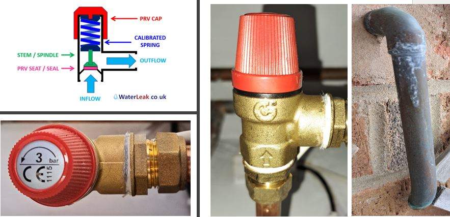
The last item to check is the pressure-reducing valve (PRV). This is a brass valve with an adjustment screw. Some models have a quick-fill feature, which allows you to pull a lever and quickly fill the system. A stethoscope is sometimes used to trouble shoot the PRV to detect if water is leaking through the valve.
Another way to test for leaking is to feel the downstream pipe and see if it is cold. In many instances, the water is fed slowly and difficult to detect. Another way to test to see if the PRV is leaking through is to shut off the valves on the feed water pipe and see if the pressure still rises. If it does, I will suspect the piping to the compression tank is restricted or the tank is flooded. If the pressure does not rise, it could be the pressure reducing valve.
Boiler explosions have been responsible for widespread damage to companies throughout the years, and that’s why today’s boilers are equipped with safety valves and/or relief valves. Boiler safety valves are designed to prevent excess pressure, which is usually responsible for those devastating explosions. That said, to ensure that boiler safety valves are working properly and providing adequate protection, they must meet regulatory specifications and require ongoing maintenance and periodic testing. Without these precautions, malfunctioning safety valves may fail, resulting in potentially disastrous consequences.
Boiler safety valves are activated by upstream pressure. If the pressure exceeds a defined threshold, the valve activates and automatically releases pressure. Typically used for gas or vapor service, boiler safety valves pop fully open once a pressure threshold is reached and remain open until the boiler pressure reaches a pre-defined, safe lower pressure.
Boiler relief valves serve the same purpose – automatically lowering boiler pressure – but they function a bit differently than safety valves. A relief valve doesn’t open fully when pressure exceeds a defined threshold; instead, it opens gradually when the pressure threshold is exceeded and closes gradually until the lower, safe threshold is reached. Boiler relief valves are typically used for liquid service.
There are also devices known as “safety relief valves” which have the characteristics of both types discussed above. Safety relief valves can be used for either liquid or gas or vapor service.
Nameplates must be fastened securely and permanently to the safety valve and remain readable throughout the lifespan of the valve, so durability is key.
The National Board of Boiler and Pressure Vessel Inspectors offers guidance and recommendations on boiler and pressure vessel safety rules and regulations. However, most individual states set forth their own rules and regulations, and while they may be similar across states, it’s important to ensure that your boiler safety valves meet all state and local regulatory requirements.
The National Board published NB-131, Recommended Boiler and Pressure Vessel Safety Legislation, and NB-132, Recommended Administrative Boiler and Pressure Vessel Safety Rules and Regulationsin order to provide guidance and encourage the development of crucial safety laws in jurisdictions that currently have no laws in place for the “proper construction, installation, inspection, operation, maintenance, alterations, and repairs” necessary to protect workers and the public from dangerous boiler and pressure vessel explosions that may occur without these safeguards in place.
The American Society of Mechanical Engineers (ASME) governs the code that establishes guidelines and requirements for safety valves. Note that it’s up to plant personnel to familiarize themselves with the requirements and understand which parts of the code apply to specific parts of the plant’s steam systems.
High steam capacity requirements, physical or economic constraints may make the use of a single safety valve impossible. In these cases, using multiple safety valves on the same system is considered an acceptable practice, provided that proper sizing and installation requirements are met – including an appropriately sized vent pipe that accounts for the total steam venting capacity of all valves when open at the same time.
The lowest rating (MAWP or maximum allowable working pressure) should always be used among all safety devices within a system, including boilers, pressure vessels, and equipment piping systems, to determine the safety valve set pressure.
Avoid isolating safety valves from the system, such as by installing intervening shut-off valves located between the steam component or system and the inlet.
Contact the valve supplier immediately for any safety valve with a broken wire seal, as this indicates that the valve is unsafe for use. Safety valves are sealed and certified in order to prevent tampering that can prevent proper function.
Avoid attaching vent discharge piping directly to a safety valve, which may place unnecessary weight and additional stress on the valve, altering the set pressure.
It depends. Some of the valves we carry run between $100-$200, as they are suitable for smaller applications. Some industrial settings may need larger or more robust valves, which can run upwards of $1,000 or $2,000.
We recommend that your maximum expected operating pressure will not exceed 90% of the valve’s set pressure. This helps to ensure the valve’s seat will stay tight.
Identifying the process media, or service, of a valve is important to set pressure. If a valve has the correct set pressure but is used on the wrong application, there’s a chance the valve won’t open when needed. This could cause an overpressure event.
No. The valve’s set pressure is measured in gauge pressure, or pounds per square inch gauge (psig), so you don’t have to take altitude into account when selecting your valve.
Back pressure can have complex effects on a valve’s set pressure, capacity, and overall performance. If you know your application will have any type of back pressure, we recommend getting in touch with one of our specialists to verify how it may affect your valve selection or performance.
When you’re shopping on Valves Depot or looking at a valve nameplate, you might see references to ASME Sections I (V stamp), IV (HV stamp), or VIII (UV stamp) in the valve specs. These refer to the ASME (American Society of Mechanical Engineers) Boiler and Pressure Vessel Code (BPVC) standard, a set of guidelines for valve manufacturing.
When you’re installing a smaller valve, preventing damage is as simple as handling the new valve with care. Some parts are fragile. But for larger, heavier valves, during installation, pay close attention to the lever — make sure your lifting straps don’t accidentally wrap around or otherwise conflict with it.
After your initial inspection, schedule maintenance every two to six months. Your maintenance interval will depend on your service conditions and the age of the valve.
Some valve models are required to have a drain hole per the ASME Boiler and Pressure Vessel Code. The drain hole helps prevent condensate from accumulating in the body that could freeze or corrode internal valve parts.
Just because your valve is leaking doesn’t necessarily mean that you need a new valve or repairs — you may need to adjust your operating procedures. Lowering your system pressure, accounting for expected pressure spikes, and regularly calibrating your gauges are a few possible ways to help stop or prevent leakage.

A little product education can make you look super smart to customers, which usually means more orders for everything you sell. Here’s a few things to keep in mind about safety valves, so your customers will think you’re a genius.
A safety valve is required on anything that has pressure on it. It can be a boiler (high- or low-pressure), a compressor, heat exchanger, economizer, any pressure vessel, deaerator tank, sterilizer, after a reducing valve, etc.
There are four main types of safety valves: conventional, bellows, pilot-operated, and temperature and pressure. For this column, we will deal with conventional valves.
A safety valve is a simple but delicate device. It’s just two pieces of metal squeezed together by a spring. It is passive because it just sits there waiting for system pressure to rise. If everything else in the system works correctly, then the safety valve will never go off.
A safety valve is NOT 100% tight up to the set pressure. This is VERY important. A safety valve functions a little like a tea kettle. As the temperature rises in the kettle, it starts to hiss and spit when the water is almost at a boil. A safety valve functions the same way but with pressure not temperature. The set pressure must be at least 10% above the operating pressure or 5 psig, whichever is greater. So, if a system is operating at 25 psig, then the minimum set pressure of the safety valve would be 30 psig.
Most valve manufacturers prefer a 10 psig differential just so the customer has fewer problems. If a valve is positioned after a reducing valve, find out the max pressure that the equipment downstream can handle. If it can handle 40 psig, then set the valve at 40. If the customer is operating at 100 psig, then 110 would be the minimum. If the max pressure in this case is 150, then set it at 150. The equipment is still protected and they won’t have as many problems with the safety valve.
Here’s another reason the safety valve is set higher than the operating pressure: When it relieves, it needs room to shut off. This is called BLOWDOWN. In a steam and air valve there is at least one if not two adjusting rings to help control blowdown. They are adjusted to shut the valve off when the pressure subsides to 6% below the set pressure. There are variations to 6% but for our purposes it is good enough. So, if you operate a boiler at 100 psig and you set the safety valve at 105, it will probably leak. But if it didn’t, the blowdown would be set at 99, and the valve would never shut off because the operating pressure would be greater than the blowdown.
All safety valves that are on steam or air are required by code to have a test lever. It can be a plain open lever or a completely enclosed packed lever.
Safety valves are sized by flow rate not by pipe size. If a customer wants a 12″ safety valve, ask them the flow rate and the pressure setting. It will probably turn out that they need an 8×10 instead of a 12×16. Safety valves are not like gate valves. If you have a 12″ line, you put in a 12″ gate valve. If safety valves are sized too large, they will not function correctly. They will chatter and beat themselves to death.
Safety valves need to be selected for the worst possible scenario. If you are sizing a pressure reducing station that has 150 psig steam being reduced to 10 psig, you need a safety valve that is rated for 150 psig even though it is set at 15. You can’t put a 15 psig low-pressure boiler valve after the reducing valve because the body of the valve must to be able to handle the 150 psig of steam in case the reducing valve fails.
The seating surface in a safety valve is surprisingly small. In a 3×4 valve, the seating surface is 1/8″ wide and 5″ around. All it takes is one pop with a piece of debris going through and it can leak. Here’s an example: Folgers had a plant in downtown Kansas City that had a 6×8 DISCONTINUED Consolidated 1411Q set at 15 psig. The valve was probably 70 years old. We repaired it, but it leaked when plant maintenance put it back on. It was after a reducing valve, and I asked him if he played with the reducing valve and brought the pressure up to pop the safety valve. He said no, but I didn’t believe him. I told him the valve didn’t leak when it left our shop and to send it back.
If there is a problem with a safety valve, 99% of the time it is not the safety valve or the company that set it. There may be other reasons that the pressure is rising in the system before the safety valve. Some ethanol plants have a problem on starting up their boilers. The valves are set at 150 and they operate at 120 but at startup the pressure gets away from them and there is a spike, which creates enough pressure to cause a leak until things get under control.
If your customer is complaining that the valve is leaking, ask questions before a replacement is sent out. What is the operating pressure below the safety valve? If it is too close to the set pressure then they have to lower their operating pressure or raise the set pressure on the safety valve.
Is the valve installed in a vertical position? If it is on a 45-degree angle, horizontal, or upside down then it needs to be corrected. I have heard of two valves that were upside down in my 47 years. One was on a steam tractor and the other one was on a high-pressure compressor station in the New Mexico desert. He bought a 1/4″ valve set at 5,000 psig. On the outlet side, he left the end cap in the outlet and put a pin hole in it so he could hear if it was leaking or not. He hit the switch and when it got up to 3,500 psig the end cap came flying out like a missile past his nose. I told him to turn that sucker in the right direction and he shouldn’t have any problems. I never heard from him so I guess it worked.
If the set pressure is correct, and the valve is vertical, ask if the outlet piping is supported by something other than the safety valve. If they don’t have pipe hangers or a wall or something to keep the stress off the safety valve, it will leak.
There was a plant in Springfield, Mo. that couldn’t start up because a 2″ valve was leaking on a tank. It was set at 750 psig, and the factory replaced it 5 times. We are not going to replace any valves until certain questions are answered. I was called to solve the problem. The operating pressure was 450 so that wasn’t the problem. It was in a vertical position so we moved on to the piping. You could tell the guy was on his cell phone when I asked if there was any piping on the outlet. He said while looking at the installation that he had a 2″ line coming out into a 2×3 connection going up a story into a 3×4 connection and going up another story. I asked him if there was any support for this mess, and he hung up the phone. He didn’t say thank you, goodbye, or send me a Christmas present.

Operating controls for boilers could be broadly defined to include burner management controls; however, this inspector guide will be limited to the pressure and temperature operating controls required by the ASME BPV Code for steam and hot water boilers.
Steam boilers require a device which senses steam pressure and cycles the burner or other source of heat in order to maintain a consistent, predetermined operating pressure. A second device is used to prevent the boiler from exceeding the maximum allowable working pressure (MAWP) indicated on the boiler nameplate.
Hot-water boilers require a device which senses water temperature and cycles the burner or other source of heat in order to maintain a consistent, predetermined operating temperature. A second device is used to prevent the boiler from exceeding the design temperature of an ASME BPV Code Section I boiler or the maximum water temperature indicated on an ASME BPV Code Section IV boiler nameplate.
The secondary device referenced above for both steam and hot-water boilers is referred to as a high-limit control and under normal conditions, would never be called upon to operate. However, if the primary, or operating, control should fail, the high-limit control must operate, stopping the burner or other source of heat. Some high-limit controls incorporate a manual reset. The purpose of this is to alert the operator that the high-limit control has been activated. The operator should then look for the problem which caused the high-limit control to activate before resetting the device and restarting the boiler.
ASME BPV Code Section I does not specifically mandate pressure or temperature controls but they will be found, in one form or another, on almost all ASME BPV Code Section I boilers. In addition, ASME Standard CSD-1 (if applicable) requires the controls on boilers with input ratings up to 12,500,000 Btu/hr. Jurisdictional regulations will specify the use of ASME Standard CSD-1 if it is mandated.
A pressure control must be installed so as to always sense pressure from the steam space of the boiler. The ASME BPV Code requirements and device manufacturer"s instructions should be followed for any installation details. When a siphon or pigtail is used to prevent live steam from entering and damaging the device, the orientation of the siphon loop is critical to the proper operation of a device containing a mercury switch. If the siphon loop is installed in the incorrect orientation shown in Figure 1, movement of the loop caused by heat and/or pressure can cause the mercury switch in the device to activate or deactivate at other than the set pressure.
Either type of operating control can be bypassed electrically with jumper wires. Jumper wires can be used legitimately by qualified service personnel during maintenance and testing, but must be removed before returning the boiler to normal operation. Jumper wires could be used inappropriately in an attempt to permanently bypass a control which has malfunctioned and will not allow the boiler to operate.
While inspecting low-pressure or high-pressure boilers, the inspector will be observing operating controls. The inspector must take the time necessary to completely evaluate the condition and operational effectiveness of these controls. The inspector should:
Compare the pressure gage reading on a steam boiler with the set pressure of the primary operating control. If the pressure gage reading is higher than the set pressure of the control, request the installation of a second, reliable pressure gage in order to determine the accuracy of the first pressure gage. If the second pressure gage reading agrees with the operating control set pressure, the first pressure gage must be recalibrated or replaced. If, however, the second pressure gage reading agrees with the first pressure gage, the boiler should be removed from service until the primary operating control can be repaired or replaced.
Compare the thermometer reading on a hot-water boiler with the set temperature of the primary operating control. If the thermometer reading is higher than the set temperature of the control, request the installation of a second, reliable thermometer in order to determine the accuracy of the first thermometer. If the second thermometer reading agrees with the operating control set temperature, the first thermometer must be recalibrated or replaced. If, however, the second thermometer reading agrees with the first thermometer, the boiler should be removed from service until the primary operating control can be repaired or replaced
Request the owner or owner"s representative test the high-limit control in accordance with the control manufacturer"s instructions. This test may involve disabling the primary operating control or setting the primary control"s pressure or temperature, as applicable, higher than the setting of the high-limit control. Since each installation can be unique, the inspector should rely on the control manufacturer"s instructions for guidance. Before returning the boiler to its normal operating condition, ensure all operating controls are enabled and set to the proper pressure or temperature.
Your pressure relief valves are the most important pieces of safety equipment in your facility or along your pipelinesystem. There’s no margin for error. Your PRVs need to work — every time. So how do you know when you can get by with a repair, or when it’s time to replace them?
In many cases, regular valve testing and repair isn’t optional. It’s mandatory. But how do you know if it’s time for a replacement? Here are three times you need to think about repairing or replacing your pressure relief valves.
Pressure relief valves are designed to open to relieve pressure in your system and then close again. In a clean environment, they may be able to open and close multiple times with no problems. But, in some cases, when a valve opens, debriscan get into the valve seat, which can prevent the valve from returning to its originalclosed position.
In some locations and industries, regulations govern how long valves are allowed to be in operation before they need to be repaired or replaced. For example, your state inspector may require that your valves be completely disassembled, inspected, repaired, and tested every five years. In extreme cases, such as if a valve is frozen, the local jurisdiction will mandate replacement.
For smaller valves and applications, you can test your valve by lifting the test lever. Note, though, thatyou shouldn’t do this too often, only about once a year.ASME UG136A Section 3 requires valves have at a minimum of 75% operating pressure versus the set pressure of the valve for hand lifting to be performed.
For larger valves and applications, you can send them to us for testing or we can visit your facility and test them online through ourElectronic Valve Testing (EVT) services.
The service and application a valve is used for affects its longevity. A valve used for clean service, such as steam, can last a long time — easily 20 years if it isn’t operated too close to the set point and gets the right preventative maintenance program. On the other hand, a valve that used for acid service, operated too close to the set point, or exposed to dirt or debris in the system will need to be replaced more often — such as every 10 years.
Our technicians are factory-trained to repair and recertify valves back to their OEM specifications. But is that the best course of action? Or should you just replace them?
In general, we recommend repairing your valves when possible to get the most out of your investment. However, sometimes, replacement is simply more cost-effective than repair.
In either case, it will certainly cost less to replace the valve than to pay for any damage you might incur from keeping it in service past its prime!
In general, it’s difficult to impossible to say exactly how long your pressure relief valves will last. It depends on several factors, including the service, the system, and how the valves are operated. The best way to both keep your valves operating correctly and identify when they need to be replaced is to put them on a regular preventative maintenance program, ideally supported by a valve management software like ValvKeep.
At Allied Valve, your safety is our first priority. Our pressure relief valve repair services can keep your valves working at their highest levels of performance.Learn more about what we can do for you.
A ship’s engine room is a complex arrangement of machinery and systems, which is used in carrying out various operations on board. One such important machinery, which has been assisting ships since the start of shipping, is the marine boiler.
Earlier, marine boilers were primarily installed on a ship for the propulsion plant, which used to run on steam (steam engine). Today, the steam generated by the boiler is utilized in various systems in the engine room, including heating of fuel for the main engine. Considering the importance of marine boilers and the risks involved with its operation on ships, there has been constant development in the industry to enhance boiler safety on board. Some even consider it one of the “deadliest” machinery systems on board.
Boiler Explosion: Many cases of boiler explosion in the past have shown how dangerous marine boiler can be if not operated professionally. Accidents happen when the fuel system within the boiler is mishandled, or when the steam pressure inside the boiler drum is not regulated.
Boiler Fire/ Meltdown: The boiler fire is another type of accident which can destroy all the tubes inside the boiler and lead to an explosion or spreading of fire within the ship.
Hot Surface: The boiler and the associated pipes, valves, and auxiliaries have a very hot surface as they carry steam to different parts of the ship. A direct skin contact with any of the exposed surface will lead to severe burn.
Other Risks: Other risks such as high pressurized parts, handling harmful chemicals, moving machinery etc. are also associated with operating marine boilers.
Needless to say, safety is a critical aspect when operating a high or even a low-pressure boiler on a ship and therefore different marine boiler devices are provided.
Boiler Safety System and Instruments: A modern marine boiler is fitted with several safety devices for the protection of the operator. For easy understanding, let us divide these instruments/devices as per the system they are fitted in –
Steam Safety System: The steam system in the boiler is a high pressure, high-temperature area. To safeguard the operator and the boiler itself, it is fitted with the following safety features:
Pressure gauge: Multiple pressure gauges are fitted to ensure the operator has an idea of the current value of pressure inside the boiler. Usually, two pressure gauges are fitted on the boiler and one line is taken from the steam drum to the engine control room, to display the steam pressure remotely.
The pressure gauges are also incorporated with cut-in and cut-out automation systems, i.e. the input from the pressure gauges are used to operate the boiler burner. When the pressure reaches the set value, the boiler burner will stop firing and when the pressure drops to a lower set value, the burner will be switched ON to raise the boiler pressure.
Safety Valve: Boiler safety valve is an extremely important safety equipment fitted on the steam drum of the boiler. As per SOLAS chapter II-1, every steam boiler and every un-fired steam generator shall be provided with not less than 2 safety valves of adequate capacity. However, with regards to the output or any other feature of a boiler or un-fired steam generator, the administration may permit only one safety valve to be fitted if adequate protection against overpressure is thereby satisfactorily provided.
Usually, an improved high lift is one of the most popular types of safety valves used on a ship. They are set to lift at the blow-off pressure and shut when the pressure reduces to the safe limit. They are set to open at 3 % above working pressure. The lift of valve is one-twelfth of the valve diameter.
Easing Gear: The easing gear is attached to the boiler safety valve. Every individual safety valve is provided with its own easing gear, which is a pulley and wire arrangement (connected to the lever of the safety valve) with an accessible handle at the lower operating boiler platform. It is used to lift the boiler safety valve in case of an emergency (without getting near to the safety valve) and to regularly test the operation of the safety valves.
Boiler Vent: Vent on the boiler drum is required to ensure boiler does not implode once it is shut down. It is normally opened when the pressure gauge shows the reading below 0.5 bars.
Water Safety System: The water system is a high-temperature system and the level and quality of the water inside the water drum plays a crucial role in the safe operation of the boiler. Following are the equipment/system fitted on the water side of the marine boiler:
Low / high water level alarm and cutout: The boiler water drum is fitted with a level sensor, which will continuously monitor the level of water inside the drum. A full drum will carry over the water or will have no space to generate steam, thus reducing the efficiency of the boiler; whereas low or no water level in the drum will lead to over-heating of tubes and can lead to fire or meltdown of the complete boiler.
The low/ high water level provides an early warning to the operator for taking appropriate action to manage the water level inside the boiler water drum.
Too low water level alarm and shut down: The initial warning provided by the above arrangement (low/high water level alarm), may not be sufficient for the operator as there can be a major leak in the tubes, leading to a reduction in the water level. A secondary safety is therefore provided i.e. Too low water level alarm and shut down, which will stop the burner firing to control the overheating of the boiler internal parts.
Water level indicators: The boiler is fitted with multiple water level indicators to make it easy for the operator to see the water drum level and ensure operational safety of the boiler.
Local gauge glasses are provided in a duplex on the boiler drum to ensure at least one gauge glass is operational in case one stops showing the level. Remote water level indicators such as a differential pressure water level sensor, probe level sensor etc. are also provided to indicate the current level in the drum at a remote position such as the engine control room.
Salinity Sensor: The boiler drum is fitted with a salinity sensor, which continuously monitors the dissolved solids content in the water. If the solid (e.g. salt) content exceeds the set value, it trips the boiler to ensure the tubes and boiler internals does not get affected due to the contamination. The operator should either blow down the boiler and feed fresh water to the drum to eliminate the cause which is resulting in high salinity (for e.g. leakage in the condenser)
Fuel Safety System: The boiler is provided with heavy or marine gas fuel oil for generating the heat in the furnace. To ensure the fuel system is operating efficiently, it is fitted with the following boiler safety features:
Low / high fuel oil temperature alarm: Modern marine boilers are meant to operate in different grades of fuel due to the port / ECA regulations for minimizing the air pollution from the ship. The oil temperature is an important factor as it controls the viscosity of the fuel which is directly related to atomization and efficient combustion inside the furnace. If the fuel temperature is not at its set value (which will vary for different grades), the alarm will sound. The operator must stop the alarm and the oil temperature should be brought to normal before restarting the boiler.
Smoke Density alarm: With more stringent rules coming up for environmental protection, the boiler exhaust is fitted with a smoke density sensor which detects the post-combustion product, especially during starting of a boiler and at low loads. If the smoke density is higher than the required value, it will sound an alarm to which the operator needs to check the combustion of the boiler
Operational Safety: Automation, alarms, and warnings have made the life of seafarers on ships a lot easier than what it used to be in terms of boiler safety. However, professional engineers rarely depend on them and always rely on the best practice for efficiently running the machinery.
Efficient hot well/ cascade tank function: Maintaining the correct hot-well temperature will decrease the steam production time of the boiler compared to a low-temperature water supply by the cascade tank
Routine furnace inspection: Boiler furnace is responsible to contain the heat within the boiler and to reduce the surface heat loss. Maintaining the furnace refractory will lead to efficient boiler steam production
Lagging: Once the steam comes out of the boiler via main steam stop valve, it is supplied to several systems via pipes and distribution valves. A proper lagging on the pipes and valves will ensure the boiler need not run extra as the steam loss will be contained. Also, it ensures the safety of ship staff from surface burns.
Maintenance: On-time maintenance such as testing of safety valve, cleaning of boiler tubes etc. will result in safe and efficient working of the marine boiler.
Safety relief valves are relatively maintenance-free devices. Even so, it is recommended that a periodic inspection of these devices be done every six to 12 months.
A common maintenance error is to add a second relief valve onto the outlet of an existing relief valve that is leaking. This “stacking” of relief valves is not permissible by code.
By installing two relief valves in sequence, you add back pressure above the first relief valve piston, causing a change in the pressure setting. For example, the estimated relieving pressure of a valve stack could be:
As the relief flow then passes through the second valve, the stack also experiences a change in relieving capacity. If any of these conditions exist, the valve should be replaced.
The condition of the discharge piping should also be inspected. Valves should be piped to ensure that they do not collect dirt and debris. The vent pipes should be protected to prevent the entrance of rain water, which would inhibit valve operation.
Relief valves should be changed out after discharge to ensure safeguarding a system with a properly set relief valve. Most systems are subject to accumulations of piping debris (i.e., metal shavings and solder impurities) as the system is fitted for installation.
These impurities are generally blown into the relief valve seats at the time the valve is discharged. The impinged debris then inhibits the relief valve from reseating at its original set pressure.
Replacement intervals for valves that have not discharged may be dictated by city, state, or federal regulations. In addition, they may also be regulated by industry standards, company policies, insurance requirements, or unwritten, accepted standards of good practice.
In the case of city, state, or federal regulations and insurance regulations, there appear to be no written rules covering the replacement schedule. However, these agencies do govern by verbal requirements requesting that system operators-owners provide proof of the reliability of existing relief valves.
Industry standardsThe International Institute of Ammonia Refrigeration (IIAR), in its Bulletin 109, IIAR Minimum Safety Criteria for a Safe Ammonia Refrigeration System, recommends that the relief valve be replaced or inspected, cleaned, and tested every five years.
ANSI STD K61.1-1989, Safety Requirements for the Storage and Handling of Anhydrous Ammonia, is very specific in its requirements. Paragraph 6.8.15 states:
“No container pressure relief devices shall be used after the replacement date as specified by the manufacturer of the device. If no date is specified, a pressure relief valve shall be replaced no later than five years following the date of its manufacture.”
In industrial refrigeration, the current recommendation is to replace the relief valve on a five-year cycle. Be sure to check with other agencies to verify that a more stringent regulation is not applicable.
Provide a pressure vessel that will permit the relief valve to be set at least 25% above the maximum system pressure. However, the relief valve setting cannot exceed the maximum allowable working pressure as stamped on the vessel the relief valve is protecting.
 Use the proper size and length of discharge tube or pipe. Correct sizing is required to prevent back pressure from building up in the discharge line, preventing the relief valve from discharging at its rated capacity.
 The use of a three-way valve with two relief devices, which complies with the code requirements for vessels 10 cu ft or more in gross volume, is recommended for any installation containing a large quantity of expensive refrigerant.
POST a QUESTION or COMMENT about pressure or pressure & temperature safety relief valves: inspection, diagnosis, installation requirements, relief valve testing, and relief valve repair procedures.
How to install, inspect, troubleshoot, repair pressure / temperature relief valves or straight pressure relief valves used on heating boilers, steam boilers, water heaters, and even on water pressure tanks. This article explains what TP or pressure relief safety valves are, why they are needed, how they work, and what goes wrong.
We describe how to test (or when not to test) relief valves, how to know that this important safety device is in trouble, including by simple visual inspection, and we answer just about any question about these important safety devices.
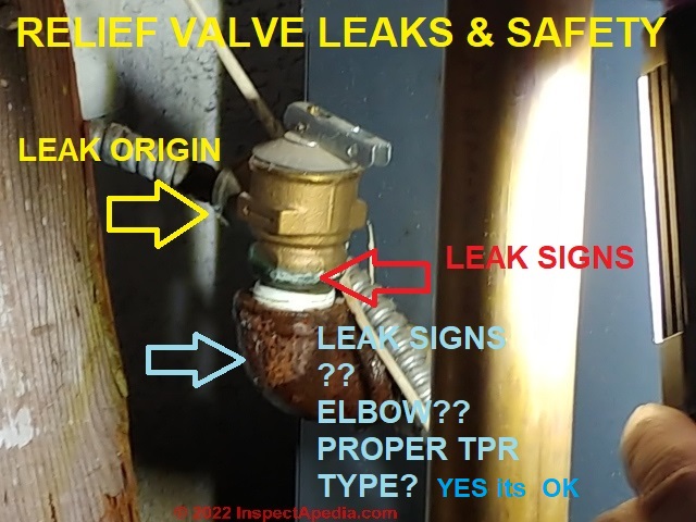
Our photo at page top shows what the typical boiler relief valve looks like. You may find this valve connected at the top of a heating boiler, at its side, or (less desirable) very nearby on boiler hot water piping. This T&P valve is unsafe, lacking a discharge tube.
Some equipment may have only a pressure relief valve with no temperature sensor. On a water pressure tank that"s fine, but on water heaters and steam or hot water heating boilers such an installation is not safe and may not comply with building codes.
This guide to relief valve inspection, testing, installation, repair, answers most questions about the use of these safety devices on heating equipment such as central heating system boilers, water heaters, steam generators and even pressurized water tank. This information aids in troubleshooting, inspection, diagnosis, and repairs.
Leaking or Previously Leaking Pressure/Temperature Relief Valves are Dangerous. Attic boiler pressure control tanks - Old Heating Boilers (steam or hot water) may have No Relief Valve at All - Check the Attic.
List of Common Boiler Temperature/Pressure Relief Valve Defects. Temperature/Pressure Relief Valve Testing Advice. Photo examples of unsafe, dangerous pressure/temperature relief valve installations.
Lots of controls are installed on modern water heaters, hot water cylinders, hot water and steam heating boilers. Many of these devices are principally concerned with safety. The combination of these devices provide a tremendous margin of safety on home and commercial heating boilers, as evidenced by the rarity with which we read in modern times of boiler explosions.
Watch out: A defective relief valve is a latent safety hazard in that the valve does not by itself cause a water heater or heating boiler to explode, but it may fail to protect against that event should other dangerous conditions causing over temperature or over pressure arise in a heating boiler or water heater.
check that the pressure relief setting is above the tank"s working pressure, that the CSA rating is greater than the heater"s input BTUH, that the valve responds to both pressure and temperature (some valves may be designed to respond only to pressure), and check the date code of the valve.
On a Watts T&P valve the serial number encodes year (first two digits) and week of manufacture (last two digits), found either on the valve"s data tag or on the under-side of the valve"s test lever.
in an inspection log to be kept at the site (record the T&P valve inspection date and inspection results). On a residential water heater the inspection log may be kept with or even written on the heater"s service and repair manual.
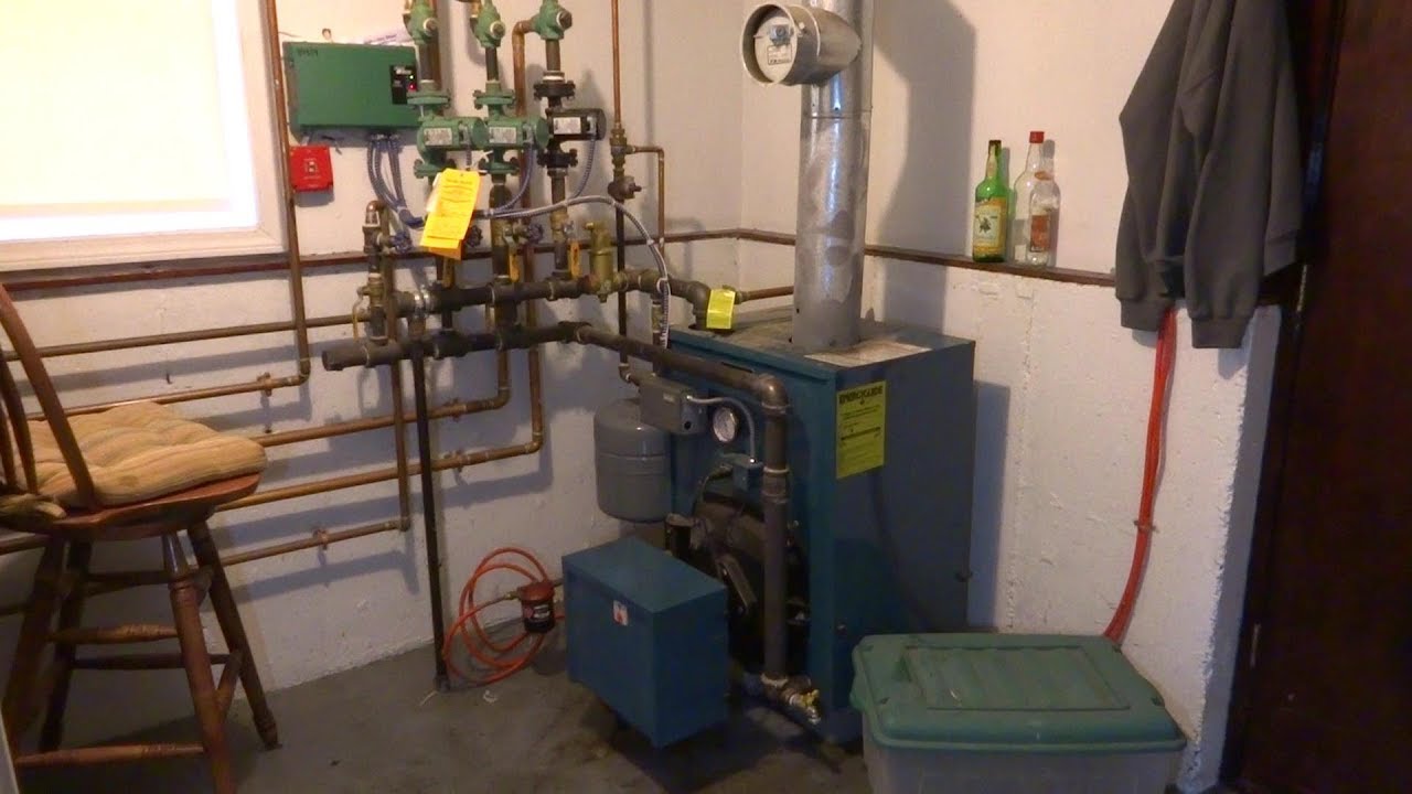
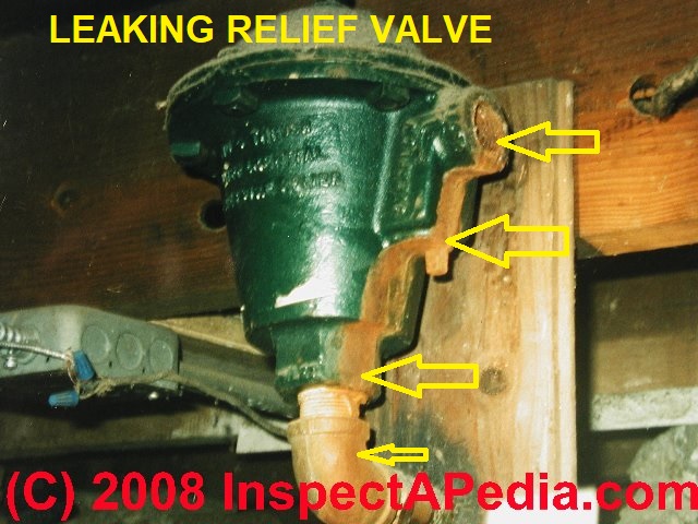
Our photo above shows an older (obsolete) type of pressure relief safety device that may be mounted close to the boiler but not right on it. This type of pressure relief device may not sense boiler temperature, just boiler pressure.
You can see that this pressure relief valve (shown above) has been leaking - it may be unsafe, as we discuss further below. Both the page top relief valve and the one in this photo are missing their discharge tubes.
Watch out: shown above is a single example of an unsafe condition at an antiquated pressure safety valve. A more complete explanation and illustration of safety hazards around TPR valves are provided in detail in each of the TPR valve categories listed above in this article.
Above is another unsafe temperature/pressure relief valve installation: the test lever that would be used to manually open, test or flush the TP valve is blocked first by having been placed up against a plaster wall and second by having had foam insulation sprayed into an opening that some smarter plumber cut into the wall to permit the lever to move.
Watch out: If the lift/test lever on a temperature/pressure relief valve is blocked from movement that prevents the valve from being tested - a step recommended at least annually by relief valve manufacturers.
Watch out: Depending on the relief valve model and design, a blocked relief valve test lever may prevent the valve from opening in response to pressure or temperature:
Special thanks to home inspector "anonymous", a member of the ASHI Technical Review Committee, for suggesting clarification of the hazards of blocked pressure or temperature relief valve test lever hazards - by private email 2017/04/21
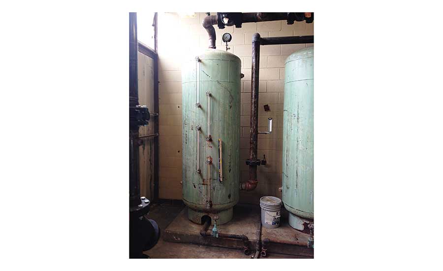
The data tag that should be found on a boiler relief valve (photo at left) gives key information and lets the owner or inspector know if the proper type of safety device has been installed.
Compare this data with the boiler capacity which will be given on the heating boiler or water heater"s data tag. Use the Input BTUh value of the heating appliance when comparing to the venting capacity of the T&) valve.
At an inspection of Vassar Temple in Poughkeepsie, NY we observed that a pressure relief valve with capacity to handle 40,000 BTUs but the heating boiler was rated for 4,000,000 BTUh!
The heating boiler was unsafe - it would normally be a simple repair to install the proper valve. The service tech had simply installed a residential-range TPR valve on a huge commercial hydronic boiler.
We don"t know if the valve has stopped leaking because a problem has been fixed (such as something else causing boiler overpressure) or if the valve has stopped leaking simply because its internals have become clogged with mineral debris which has been left behind as hot water evaporated.
The pressure temperature relief valve shown at left was dripping, but visual inspection showed that it was clogged with mineral debris left behind as boiler water leaked out and evaporated.
The mineral debris can, as you see in this photo, obstruct movement of the spring and valve internal parts, preventing it from opening when it"s needed.
Above, inspection notes on a relief valve found on a 1990s Weil McLain gas fired boiler in Two Harbors, Minnesota, during a heating inspection and tune-up. The service technician indeed called for replacement of this TPR valve.
The yellow arrow points to leak stains at the mouth of the TPR valve - so we know that this is a leak point of origin, possibly the only one at this relief valve.
For the TPR valve installation shown above one might also ask: why is this heating boiler TPR valve installed on a 90 degree elbow? Is this the proper TPR valve for a heating boiler?
Yes, for many hydronic heating (hot water) boiler applications, Watts, Apollo and other manufacturers provide some models of temperature/pressure relief valves that do not require a temperature probe that must insert into the boiler (and thus that would not fit on a pipe elbow).
Watch out: the relief valve on any heated or pressure vessel must be of the proper type for that type of equipment, and it must be capable of opening at the necessary temperature and pressure to protect the device, and finally, it must also have adequate venting capacity or venting rate.
For example, a heating boiler TPR like the Watts Series 335 is a smaller relief valve for popular size boilers up to 510,000 BTUs at 30psi (2.11 bar). If you found this TPR on a heating boiler whose input BTUH was greater than 510,000 BTUs that installation would be improper and unsafe.
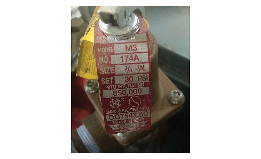
Fortunately you can usually confirm the relief valve brand, model, and intended use as well as its venting capacity simply by inspecting the data tag found right on the valve itself.
Watts 174A PRESSURE RELIEF VALVE SPECIFICATIONS [PDF] - retrieved 2022/11/02, original source: https://www.watts.com/products/plumbing-flow-control-solutions/relief-valves/pressure-only-relief-valves/174a
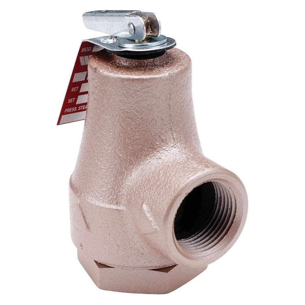
Series 174A Boiler Pressure Relief Valves are used in hot water heating and domestic supply boiler applications to protect against excessive pressures on all types of hot water heating supply boiler equipment.
Excerpt: Series 210-5 Automatic Gas Shutoff Valves are used in gas water heater applications to protect against overheating water in the domestic hot water supply heating system.
It is a self-contained device that consists of Buna-N disc-to-metal seating, manual reset button to reopen the valve after an automatic shutoff, trip latch assembly and stainless steel spring seats to close the valve at a controlled temperature, and thermostat with extension tube which operates trip latch in response to water temperature.
WATTS SERIES 335 RELIEF VALVE INSTALLATION INSTRUCTIONS [PDF] (2019) Watts Corporation, Web: www.watts.com Tel: (978) 689-6066 retrieved 2022/04/01 original source: https://www.watts.com/dfsmedia/0533dbba17714b1ab581ab07a4cbb521/24691-source/es-335-pdf
Series 415 Steam Safety Relief Valves are used in commercial and industrial applications for low-pressure, steam heating boilers and process equipment.
A client described finding her son and his friends in the basement playing "steam boat". They had tied a string through the little hole in the relief valve discharge lever, running the string up over a boiler pipe near the ceiling.
By pulling on the string the boys created an exciting blast of hot steamy water coming out of the boiler. Luckily none of them was scalded by this game.
At a home inspection in New York a real estate agent burst into tears while telling us how her son had lost an eye when he and friends played with a boiler relief valve and he was shot in the face with scalding water. A proper discharge tube could have prevented this tragedy.
See RELIEF VALVE DISCHARGE TUBE for complete details about the installation specifications & inspection defects of TPR valve drain piping and handling of spillage from TPR valves
Watch out: While it is possible to "open" a boiler TP relief valve by lifting its "test" lever, unless you are a trained heating service technician or plumber, and unless you have a spare TP valve of the proper size in your hand, we advise against "testing" a TP relief valve by opening this lever during a building inspection.
And in our OPINION, even though T&P valve instructions provided by the manufacturer recommend annually testing the valve using its try-lever, that"s better done by your trained heating service technician or plumber during annual service.
Besides a leak problem that could require you to shut down the equipment and make you sorry you ever touched the valve, there are scalding-burn hazards.
See that the boiler pressure is at or below the rated valve-opening pressure or temperature by checking the (imprecise) boiler gauge readings against the valve tag data when the boiler has heated it self up to its "shut off" point.
Check that the Temperature/Pressure relief valve has a discharge tube properly installed and that the discharge is not blocked by anything whatsoever, that it has not been reduced in size, is not crimped, damaged, corroded, leaking, nor piped "up" nor piped to a hidden location.
as we explain above in this article, the BTUh discharge capacity of the pressure/temperature relief valve must be greater than the input BTUh rating of the heating appliance it is intended to protect.
For pressure-only relief valves such as those used on water pressure tanks, the valve must be able to discharge pressure at a rate greater than the pump or other pressure source can deliver water under pressure to the storage tank.
Check that the Temperature/Pressure relief valve data tag is in place - you need this information to check the valve"s capacity and your plumber or heating technician will need it when replacing a leaky or defective TPR valve.
Read more about your particular equipment"s TPR valve requirements in the articles listed at the start of this page. Or if you think worrying about T&P valves is a bunch of hooey,
Some equipment such as some gas fired water heaters may use an automatic gas shutoff valve instead of a conventional water-dumping pressure/temperature relief valve.
An automatic gas shutoff valve will close to stop the fuel supply to a gas fired water heater if the temperature is found to be too high and thus unsafe.
Can it be rebuilt or can I use another valve such as a Watts 335 M2 to replace it. the Watts 174a is fairly expensive. - 2022/10/27 by private email from Anonymous
Although I have made emergency midnight repairs to leaking relief valves in order to keep heat going, it"s not a procedure that I would recommend. The risks are simply too great.
There are rebuild kits sold by Watts and other manufacturers for some of their pressure/temperature relief valves, but considering the product of multiplying the small probability that you make a mistake times the tremendous penalty if there is a BLEVE explosion in your building, I"d still prefer to simply replace the valve, especially in a residential application where there are not trained and experienced PRV rebuild technicians at hand.
In my opinion it"s very dangerous to try to rebuild a pressure relief valve and much quicker and less expensive to simply replace it with the proper unit.
Critical is the valve"s BTU dump rating. You can always put on a valve that would dump BTUs faster but you can never put on a valve that would dump be to use at a lower rate than the factory requirement.
Home heating boiler of the valve is of course going to be rated to open at temperatures over 200 or pressures over 30 PSI. So it"s the dump rate capacity that"s critical along with the tapping diameter.
Where you"d get into trouble would be, at the very least, a case of putting that relief valve on a high BTUh boiler - which isn"t your case as you gave your boiler"s BTUH (input?) as 160,000.
This valve must be installed by a licensed plumbing contractor in accordance with these instructions. Repair or alteration of valve in any way is prohibited by national safety standards/local codes.
[The design and function of this pigtail is not defined in the question nor photo: we see relief valve that drains upwards and uses a "pigtail" whose function is not known: is this a temperature sensor shutoff control, at its base? - Ed.]
The operating pressure ranges are different, and the water temperature sensor on the steam or hot water boiler TPR valve would of course prevent mounting it directly onto a water pipe.
A low pressure steam boiler PRV would open at less than 5 or 10 psi while a water pressure tank at a typical home may see normal pressures up to 50 to even 75 psi.
If you do not drain the boiler to below the point of attachment of the relief. You need to be prepared for water viewing or leaking out during the changeover but some plumbers are able to cope with that by being prepared with the new valve already taped with Teflon tape and ready to screw in and of course bucket in a mop.
To install a new relief valve on an oil fired boiler do you have to drain the boiler or can you just pop the relief valve, relieve the pressure, shut the water feed to the boiler then remove the old relief valve
Replaced water pipes with Pex, installed Pex rated relief valve set my heater to 120* but when it turns on it heats to 130* and my relief valve opens at 117*?
Pressure relief valve continues to drip, I replaced valve and expansion tank, water pressure gauge is around 12psi and rises to about 18psi when running yet it still starts to drip when furnace is running
RELIEF VALVES - TP VALVES at InspectApedia.com - online encyclopedia of building & environmental inspection, testing, diagnosis, repair, & problem prevention advice.
[16] Boilers, Boiler Conversions, James E. Brumbaugh, ISBN 0-672-23389-4 (v. 1) Volume II, Oil, Gas, and Coal Burners, Controls, Ducts, Piping, Valves, James E. Brumbaugh, ISBN 0-672-23390-7 (v. 2) Volume III, Radiant Heating, Water Heaters, Ventilation, Air Conditioning, Heat Pumps, Air Cleaners, James E. Brumbaugh, ISBN 0-672-23383-5 (v. 3) or ISBN 0-672-23380-0 (set) Special Sales Director, Macmillan Publishing Co., 866 Third Ave., New York, NY 10022. Macmillan Publishing Co., NY
TECHNICAL REFERENCE GUIDE to manufacturer"s model and serial number information for heating and cooling equipment, useful for determining the age of heating boilers, furnaces, water heaters is provided by Carson Dunlop Weldon & Associates


 8613371530291