
boiler safety valve popping test price

The Popping Test or Pop Test is a set pressure test of Pressure Relief Valve (PRV). It is done by compressing air into the inlet of PRV until the valve opens. Engineers then compare the opening force with the set pressure of the PRV to see whether the valve functions as specified.
When pressure surpasses the safety threshold, relief valves pop off. The “popping off” action expels surplus pressure until the tank’s pressure drops to the designated minimum pressure. The valve then resets and closes automatically after completing the blowdown procedure.
Safety is imperative and test technicians should always behave as if the valve under pressure will physically implode at any moment. ASME Section I Division VIII covers testing criteria for pressure vessel and boiler applications. Other codes such as API may apply depending on the application.
Before testing, determine the set pressure of the PRV. Properly manufactured and serviced PRVs have a set pressure engraved on a tag that’s riveted onto the body. Ensure the gauge you’re using has the proper measuring range for the pressure you’ve set.
Reduce the pressure gradually and record the reseating pressure (the pressure at which the valve closes). This happens instantly if the pressure source contains too low of a volume, thus making the seating pressure too hard to record.
Even though the fundamental PRV testing technique is relatively straightforward, it produces results based on simple observation with minimal backing data. Provision of signed certifications allows for little to no traceability other than the technician’s word.
Always stay within the test stand’s pressure limits and ensure the test stand erects correctly. Ensure the valve’s escaping pressure directs away from the operator and that everyone in the test area wears safety shields and eye protection.
With this in mind, the application of pressure Relief Valves should be assigned only to fully trained personnel and strictly comply with rules provided by the governing codes and standards.
Bench testing provides the most popular type of pressure relief valve testing because it allows for work to occur in a controlled shop environment. Testing of valves that have already been in service, requires shutdown of the process system. Then, a lab takes receipt of the valve, checks it, and prepares it for testing.
An accurate pressure relief valve testing approach that does not need valve removal or facility downtime is inline testing. A competent technician can test valves in the system using inline safety relief valve testing equipment to determine the actual setpoint. Any testing that does not require bench testing may be a suitable candidate for inline pressure relief valve testing. It does away with the downtime requirement and delivers highly accurate results.
While not a popping test, all pressure relief valves require regular manual testing. An operated-in-place test occurs by manually activating the test lever on the valve. This ensures the valve can open and close tightly, but it does not validate its opening and closing pressure. This test requires quarterly or bi-annually to ensure the most basic functionality of safety relief valves.
The accumulation test is a boiler safety test that determines whether the safety valves can release steam quickly enough to keep the pressure rising by 10%. The main steam stop valve closes during this safety valve accumulation test. With the burner on, it validates that the steam pressure will not climb over 10% prior to the safety valve releasing excess steam pressure to the atmosphere.
Hydro testing, more formally called hydrostatic testing, is performed on pressure vessels to check for leaks. This testing completely fills a pressure vessel with water and pressures it. Once pressurized, leaks can be detected. Testing occurs in accordance with ASME Section VIII Division I.

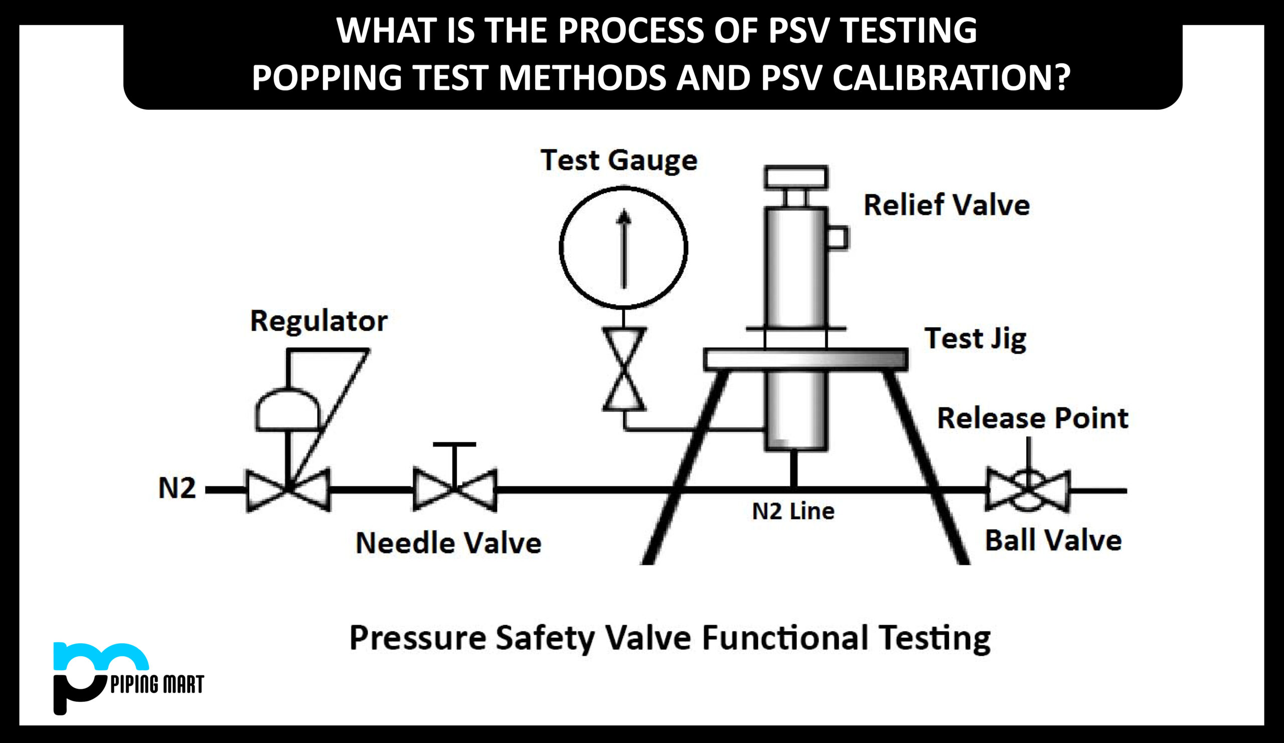
PSV or pressure safety valve is a device to protect the entire system. But to be confident and avoiding of leaving any chance of risk of PSV popping we need to test each and every Pressure safety valve with a specified PSV popping test procedure.
Testing of PSV and its procedure can be different but the findings of each method is to verify the exact working of the Pressure safety valve. In this article we will learn the following:
A pressure relief valve is a safety device that is designed to safeguard pressure-holding equipment during an event of overpressure of the equipment. An overpressure event means a condition that would cause pressure in a vessel that increases beyond the designed pressure or maximum allowable working pressure of that system.
The primary purpose of the pressure relief valve is to protect life and properties from overpressurization of equipment of the system by venting out fluid from overpressurized vessels.
Standard safety valve – A valve in which the opening reaches the degree of lift only necessary to be discharged within a pressure rise of not more than 10% (The valve is characterized by a pop type action and is sometimes known as high lift).
Full lift safety valve – A safety valve that opens rapidly within a 5% pressure rise up to the full lift as limited by the design. The amount of lift up to the rapid opening (proportional range) shall not be more than 20%.
Direct loaded safety valve – A safety valve in which the opening force underneath the valve disc is opposed by a closing force such as a spring or a weight.
Proportional safety valve – A safety valve that opens more or less steadily in relation to the increase in pressure. Sudden opening within a 10% lift range will not occur without a pressure increase. Following opening within a pressure of not more than 10%, these safety valves achieve the lift necessary for the mass flow to be discharged.
Diaphragm safety valve – A directly loaded safety valve in which linear moving and rotating elements and springs are protected against the effects of the fluid by a diaphragm.
Bellows safety valve – A direct loaded safety valve where sliding and (partially or fully) rotating elements and springs are protected against the effects of the fluids by a bellows. The bellows may be of such design that they compensate for the influences of backpressure.
Controlled safety valve– This type of pressure safety valve consists of the main valve and a control device. It also includes direct acting safety valves with supplementary loading in which, until the set pressure is reached, an additional force increases the closing force.
The PSV popping test or Pop test is a set pressure test of pressure safety valves. It is done with the help of compressed air which let flow it in the inlet of PSV until it opens. Then the authorized person for PSV calibration compares the opening force with the set pressure to see whether the valve works well or not.
When the inlet pressure of the pressure safety valve surpasses the threshold pressure, the “popping off” action is produced until the system pressure drops to the designated minimum pressure. The pressure safety valve then resets itself and closes down automatically.
Before testing, Set pressure needs to be determined by the pressure safety valve. A properly manufactured and serviced PSV has a set pressure engraved on the tag which is riveted on the body of the PSV.
Reduce the pressure gradually and record the reseating pressure, i.e. The pressure at which the valve will close. This happens instantly if the pressure source contains too low of a volume, thus making the seating pressure too difficult to record.
Even though the fundamental PRV testing technique is relatively simple, it produces results based on simple observations. Provision of signed certifications allows for little to no traceability other than the technician’s error.
Before putting a PSV into operation each pressure safety valve needs to be tested to protect equipment against overpressure. So it is important that every PSV has to be tested. There are 02 ways of testing of pressure safety valve:
Bench testing is the most popular type of method for testing pressure safety valves because it allows testing PSV in a controlled shop environment. Testing of valves that is already installed in the system requires the system to shut down.
Bench testing of PSV requires removing the pressure-relieving valve from its position and then carrying out a full functional test to check the behavior of the valve in case of overpressurizing.
Correspondingly, PSV testing cost less per testing of the valve in bench testing. But it can result in loss of production if the equipment is shut down or the removal of PSV requires for testing purposes.
When a PSV does not need the removal of the valve from installation or shut down the system is called “Inline or Online PSV testing”. A competent technician can test valves in the system using inline safety relief valve testing equipment to determine the actual setpoint.
In situ, PSV testing proves to be cost-effective as it does not require a plant shut down. But on the other hand, per PSV testing costs are much higher.
When PSV is already installed in the system or attached to the pressure holding equipment, it is costly to test pressure safety valves. In this case, PSVs are tested while in operational conditions. There are two ways of operational testing as follows:
The accumulation testing of PSV is a boiler safety test that determines whether the safety valves can release fluid quick enough to keep the pressure when by more than 10%. The main steam stop valve closes during this testing of the pressure safety valve.
The burner installed on it indicates that the steam pressure will not increase over 10% prior to the safety valve releasing excess steam pressure into the atmosphere.
Hydro testing, also called hydrostatic testing, is performed on pressure vessels to check for leaks. This testing completely fills a pressure vessel with water and pressures it. Once pressurized, leaks can be detected.
Every Pressure safety valve has a set pressure engraved on a plate which is riveted to its body. A set pressure needs to verify before making it functional for any system or pressure holding equipment. Some of the reasons why we need to perform a calibration test of PSV are as follows:
Sometimes, it has been observed that the closed position of the valve is not being activated for a required longer time. This affects the set pressure, so it is a good practice to test the valve.
Overpressure: This is pressure above-set pressure at the point where the valve will open fully. It has a tolerance of up to 10% above the set pressure.
A pressure safety valve or PSV is the last line of defense for all pressure holding systems and equipment that protect it from getting overpressurized. Working of Pressure is completely a mechanical system, hence this needs to be verified before installing it in operations.
It can be hazardous during the calibration or PSV popping test procedure. So, taking care of the operator and testing technician need to be done to make all the processes safe and harmless.
PSV popping test can be done either after installation or before installation. In both cases, the method of testing and its medium can be different to observe the result.

For many years, ultrasound has been utilised by various vendors as an additional method to find the set point in cases the standard diagrams are hard to analyse. This can be the case when testing safety valves on liquid services.
Within an extensive benchmark test, METRUS in co operation with Sweden‘s biggest nuclear power station Ringhals AB investigated the approach to use ultrasound as an additional indication for the set point on liquid service safety valves. The result of 55 tests on different valves is that the „Ultrasound point“ is completely depending on the seat condition. This result perfectly first the fact that ultrasound will detect the start to leak point and not the set point (start to lift point).
Only on a new or freshly serviced valve, the set point will be close to the ultrasound point. Even tiniest soiling or improper maintenance will cause the ultrasound to severely „drift away“ from the true set point. Within a typical online safety valve testing scenario where a valve has not bee serviced for a year or more, it is not at all recommended to use ultrasound to identify the set point.
There are still two useful applications for ultrasound within online safety valve testing. A very simple but effective use is to compare the sound level of the valve before and after the test. Comparing those sound levels will indicate if after the test (disk lift) the valve is left in a similar condition to its previous untested state. This could be first information if the valve did properly reseat and seal after it has been lifted. White Paper – Online safety valve testing METRUS Valve Test Bench Exellence
Knowing why safety valves should be tested online and how this is done in theory, it is most helpful to get an idea of the every day questions you will have to deal with. It will enable you to imagine how online safety valve testing appears in real life.
Plant operators are often surprised when being asked by online testing engineers whether it is a problem to open a valve. Considering the definition of the set point to be the initial moment when the disk starts to lift the safety valve disk must lift to find that point in a test diagram. It very much depends on the test equipment how long and high the valve will open, but it definitely has to open. geöffnet wird.
To test a safety valve, it must be possible to lift the disk and measure the force when doing so. If a safety valve has a spindle, it is possible in 95% of all cases to test it online. Some valves might require a simple spindle modification. This depends on the valve and the adapter solution how to „connect“ the test rig. Valves that do not have a spindle at all can not be tested.
Valves installed on extremely dirty fluids like bituminous crude oil should not be tested unless they are equipped with a rupture disk to keep the seat clean. Dirt could prevent the disk from sealing properly and the valve will remain leaking after the test. It the maintenance departments decision whether to agree with slightly lifting a valve or not.
Safety valves installed in EEx areas require special equipment to operate the test rig. If such equipment is available, it is important to check the specific EEx certificate for the approved EEx class and EEx area. As of now and to our best knowledge, there is no online safety valve testing system available that has an EEx approval for the whole machine. The test rigs are approved but the power unit usually has to stay outside the EEx area or have to be protected with special temporary solutions.
A frequent question to be found in industry is „what is the highest set point and the largest nominal diameter you can test?“. According to the online testing formula of fig. 1 the set pressure is calculated from line pressure, seat area and test force. Those parameters interact. The more line pressure is to be found under the safety vales disk the less force is required to lift (test) it. A final statement can never be made as it depends on seat area, set point and line pressure, whether or not the force capacity of specific equipment will be strong enough to test a valve.
Some suppliers claim that their equipment can test „any“ safety valve. Technically speaking it means raising the line pressure will lead to a remaining test force small enough to be covered by the test equipments force capacity. As online safety valve testing should not affect the plant operation this statement is not very respectable. Usually the line pressure can not be changed significantly just to test a valve.
Thinking about the largest valves, small and medium valves are often forgotten. But those ½“ and 1“ valves built the majority of valves to be found in industry. It is a technical fact, that each measurement task requires suitable sensor ranges. Large valves require large forces and small valves usually small forces. The operational range of online safety valve test equipment is therefore not only defined by its strongest force capacity. It is a question how accurate it can deal with a variety of forces and pressures – small and large.
Online safety valve testing offers major cost saving potential. In most cases it is cheaper than workshop testing after comparing direct testing costs. This of course requires the test equipment to be efficient in handling and operation.
Safety valves need to be tested at various locations within a plant. It is common to move the test equipment a few times during a test day. Different valve types to be tested require retooling of the test rig. In every day life the equipment will be packed and unpacked several times and it will require adaptation to fit the test rig on the safety valve. Valves will be located on top of tall reactors and on difficult to reach places under or behind pipelines.
The test equipments performance is significantly defined by its mechanical performance – weight and flexibility. The time for unpacking and rigging up as well as for wiring all sensors etc. determines, how fast the individual valve test will be. And in many cases the safety valve requires adjustment. Depending on how long it takes to take the rig off the safety valve, testing and re-testing will be fast and efficient or time consuming.
Within a typical online safety valve test scenario, a valve might need to be adjusted. To adjust a valve, it requires to remove the rig (RR) adjust the valve (VA) and reinstall (RI) the rig before you can carry out the next test to see, if the adjustment was successful. This is done usually two times until a satisfying set pressure is adjusted.
The relation between handling and testing time in average test equipment is about 1/5. It becomes obvious that total test time and efficiency are significantly depending on the test rig performance – weight, portability and speed of set up / dismantling.
As important as an efficient test rig handling is a clearly structured software or control system. The technician will have to deal with a lot of test data and to generate reports. With the TESON® system the technician controls the test completely from the software. The software should support the working process and enable the user to keep an eye on all relevant data without clicking through several hidden menu hierarchies. Data should be stored in databases and generating reports has to be flexible and easy. As most companies use individual test reports as well as overview lists, it is a must to have the software generating all those reports without additional work.
It may happen that safety valves stay open after the test. To make sure that such event does not affect the plant operation, a concept to remotely close the safety valve, using the test rig is absolutely necessary for safe online safety valve testing.
Testing safety valves online is not at all dangerous as long as the procedure is done properly and the system performs as it should. But there are rare scenarios in which a plant disturbance could appear, especially if a safety valve stays open or gets damaged.
Online safety valve test equipment today is either manually or electronically controlled. Electronic systems support the test process and monitor test limits, taking a lot of responsibility from the technician. TESON® e.g. automatically drives the complete lifting process, monitoring all sensor signals for pre calculated test limits. But electronic systems are sensitive to power black outs as well as to software malfunctions. To deal professionally with those, the online safety valve testing system must have an extensive safety system to guarantee the safety valve will never be blocked open or damaged – whatever might happen.
Manually controlled system are not sensitive to power black outs or system failures. They leave the full control over the test process to the technician. It is up to the technician to control the lifting force and whether or not to overload a valve. Especially with manually controlled system experience plays an important role as the safety issue is basically the human factor. Despite that even manually driven system must have some safety features to respond to hardware or hydraulic malfunction.
Considering the number of parameters to be considered and monitored during an online safety valve test, digital systems are definitely superior as the chance of malfunction and power black outs is considerably small if the systems are well designed and extensively tested. Even after intensive training and years experience it is barely possible for a technician to compete with the reliability and response time of a digital system. Considering the background of online safety valve testing it is a derived requirement of the system to be safely and correctly operated with minimum skill and experience.
When thinking of a first time investment, it is very often the purchase price that plays an important role. But if you consider the cost saving potential of online safety valve testing or the profit you could make with a service, it becomes obvious that there is more to be considered to get a real view on the cost of ownership.
Support from your supplier will be crucial for your business. If you are facing time sensitive testing sessions and your equipment gets damaged or you come across complex questions, delays of operations or loosing your customer to the competition can cause severe loss of profit. The system vendor should be able to minimize downtimes with an intelligent support strategy. This includes 24 h availability of technical support, access to most spare parts in local markets and availability of rental equipment to substitute yours during service and repair. The more a supplier is focused on the online safety valve testing business, the better resources he will offer to support your every day work.
Like all measuring equipment, online safety valve testing systems require calibration. Sensors and measuring electronic need calibration (typically every 2-3 years) to harmonize with ISO quality standards. Suppliers must be able to either offer you a calibration service or advice you where to get such service. To minimize transportation costs, the parts and modules that need calibration should be easy to isolate for shipping.
The variety of valves to be found in industry is huge. It is not at all practical to own every type of special equipment that might be required one day to test special applications. Your investment will be significantly lower if you can own core components that cover the majority of your every day online testing needs. Your supplier should offer you special extension for rent to cover the remaining applications once they are required.
We hope this white paper could draw a picture what online safety valve testing is about. If you have any further related question, please feel free to contact METRUS at any time. It will be our pleasure to support and consult you..

There is a wide range of safety valves available to meet the many different applications and performance criteria demanded by different industries. Furthermore, national standards define many varying types of safety valve.
The ASME standard I and ASME standard VIII for boiler and pressure vessel applications and the ASME/ANSI PTC 25.3 standard for safety valves and relief valves provide the following definition. These standards set performance characteristics as well as defining the different types of safety valves that are used:
ASME I valve - A safety relief valve conforming to the requirements of Section I of the ASME pressure vessel code for boiler applications which will open within 3% overpressure and close within 4%. It will usually feature two blowdown rings, and is identified by a National Board ‘V’ stamp.
ASME VIII valve- A safety relief valve conforming to the requirements of Section VIII of the ASME pressure vessel code for pressure vessel applications which will open within 10% overpressure and close within 7%. Identified by a National Board ‘UV’ stamp.
Full bore safety valve - A safety valve having no protrusions in the bore, and wherein the valve lifts to an extent sufficient for the minimum area at any section, at or below the seat, to become the controlling orifice.
Conventional safety relief valve -The spring housing is vented to the discharge side, hence operational characteristics are directly affected by changes in the backpressure to the valve.
Balanced safety relief valve -A balanced valve incorporates a means of minimising the effect of backpressure on the operational characteristics of the valve.
Pilot operated pressure relief valve -The major relieving device is combined with, and is controlled by, a self-actuated auxiliary pressure relief device.
Power-actuated safety relief valve - A pressure relief valve in which the major pressure relieving device is combined with, and controlled by, a device requiring an external source of energy.
Standard safety valve - A valve which, following opening, reaches the degree of lift necessary for the mass flowrate to be discharged within a pressure rise of not more than 10%. (The valve is characterised by a pop type action and is sometimes known as high lift).
Full lift (Vollhub) safety valve -A safety valve which, after commencement of lift, opens rapidly within a 5% pressure rise up to the full lift as limited by the design. The amount of lift up to the rapid opening (proportional range) shall not be more than 20%.
Direct loaded safety valve -A safety valve in which the opening force underneath the valve disc is opposed by a closing force such as a spring or a weight.
Proportional safety valve - A safety valve which opens more or less steadily in relation to the increase in pressure. Sudden opening within a 10% lift range will not occur without pressure increase. Following opening within a pressure of not more than 10%, these safety valves achieve the lift necessary for the mass flow to be discharged.
Diaphragm safety valve -A direct loaded safety valve wherein linear moving and rotating elements and springs are protected against the effects of the fluid by a diaphragm
Bellows safety valve - A direct loaded safety valve wherein sliding and (partially or fully) rotating elements and springs are protected against the effects of the fluids by a bellows. The bellows may be of such a design that it compensates for influences of backpressure.
Controlled safety valve - Consists of a main valve and a control device. It also includes direct acting safety valves with supplementary loading in which, until the set pressure is reached, an additional force increases the closing force.
Safety valve - A safety valve which automatically, without the assistance of any energy other than that of the fluid concerned, discharges a quantity of the fluid so as to prevent a predetermined safe pressure being exceeded, and which is designed to re-close and prevent further flow of fluid after normal pressure conditions of service have been restored. Note; the valve can be characterised either by pop action (rapid opening) or by opening in proportion (not necessarily linear) to the increase in pressure over the set pressure.
Direct loaded safety valve -A safety valve in which the loading due to the fluid pressure underneath the valve disc is opposed only by a direct mechanical loading device such as a weight, lever and weight, or a spring.
Assisted safety valve -A safety valve which by means of a powered assistance mechanism, may additionally be lifted at a pressure lower than the set pressure and will, even in the event of a failure of the assistance mechanism, comply with all the requirements for safety valves given in the standard.
Supplementary loaded safety valve - A safety valve that has, until the pressure at the inlet to the safety valve reaches the set pressure, an additional force, which increases the sealing force.
Note; this additional force (supplementary load), which may be provided by means of an extraneous power source, is reliably released when the pressure at the inlet of the safety valve reaches the set pressure. The amount of supplementary loading is so arranged that if such supplementary loading is not released, the safety valve will attain its certified discharge capacity at a pressure not greater than 1.1 times the maximum allowable pressure of the equipment to be protected.
Pilot operated safety valve -A safety valve, the operation of which is initiated and controlled by the fluid discharged from a pilot valve, which is itself, a direct loaded safety valve subject to the requirement of the standard.
The common characteristic shared between the definitions of conventional safety valves in the different standards, is that their operational characteristics are affected by any backpressure in the discharge system. It is important to note that the total backpressure is generated from two components; superimposed backpressure and the built-up backpressure:
Subsequently, in a conventional safety valve, only the superimposed backpressure will affect the opening characteristic and set value, but the combined backpressure will alter the blowdown characteristic and re-seat value.
The ASME/ANSI standard makes the further classification that conventional valves have a spring housing that is vented to the discharge side of the valve. If the spring housing is vented to the atmosphere, any superimposed backpressure will still affect the operational characteristics. Thiscan be seen from Figure 9.2.1, which shows schematic diagrams of valves whose spring housings are vented to the discharge side of the valve and to the atmosphere.
By considering the forces acting on the disc (with area AD), it can be seen that the required opening force (equivalent to the product of inlet pressure (PV) and the nozzle area (AN)) is the sum of the spring force (FS) and the force due to the backpressure (PB) acting on the top and bottom of the disc. In the case of a spring housing vented to the discharge side of the valve (an ASME conventional safety relief valve, see Figure 9.2.1 (a)), the required opening force is:
In both cases, if a significant superimposed backpressure exists, its effects on the set pressure need to be considered when designing a safety valve system.
Once the valve starts to open, the effects of built-up backpressure also have to be taken into account. For a conventional safety valve with the spring housing vented to the discharge side of the valve, see Figure 9.2.1 (a), the effect of built-up backpressure can be determined by considering Equation 9.2.1 and by noting that once the valve starts to open, the inlet pressure is the sum of the set pressure, PS, and the overpressure, PO.
Balanced safety valves are those that incorporate a means of eliminating the effects of backpressure. There are two basic designs that can be used to achieve this:
Although there are several variations of the piston valve, they generally consist of a piston type disc whose movement is constrained by a vented guide. The area of the top face of the piston, AP, and the nozzle seat area, AN, are designed to be equal. This means that the effective area of both the top and bottom surfaces of the disc exposed to the backpressure are equal, and therefore any additional forces are balanced. In addition, the spring bonnet is vented such that the top face of the piston is subjected to atmospheric pressure, as shown in Figure 9.2.2.
The bellows arrangement prevents backpressure acting on the upper side of the disc within the area of the bellows. The disc area extending beyond the bellows and the opposing disc area are equal, and so the forces acting on the disc are balanced, and the backpressure has little effect on the valve opening pressure.
Bellows failure is an important concern when using a bellows balanced safety valve, as this may affect the set pressure and capacity of the valve. It is important, therefore, that there is some mechanism for detecting any uncharacteristic fluid flow through the bellows vents. In addition, some bellows balanced safety valves include an auxiliary piston that is used to overcome the effects of backpressure in the case of bellows failure. This type of safety valve is usually only used on critical applications in the oil and petrochemical industries.
Since balanced pressure relief valves are typically more expensive than their unbalanced counterparts, they are commonly only used where high pressure manifolds are unavoidable, or in critical applications where a very precise set pressure or blowdown is required.
This type of safety valve uses the flowing medium itself, through a pilot valve, to apply the closing force on the safety valve disc. The pilot valve is itself a small safety valve.
The diaphragm type is typically only available for low pressure applications and it produces a proportional type action, characteristic of relief valves used in liquid systems. They are therefore of little use in steam systems, consequently, they will not be considered in this text.
The piston type valve consists of a main valve, which uses a piston shaped closing device (or obturator), and an external pilot valve. Figure 9.2.4 shows a diagram of a typical piston type, pilot operated safety valve.
The piston and seating arrangement incorporated in the main valve is designed so that the bottom area of the piston, exposed to the inlet fluid, is less than the area of the top of the piston. As both ends of the piston are exposed to the fluid at the same pressure, this means that under normal system operating conditions, the closing force, resulting from the larger top area, is greater than the inlet force. The resultant downward force therefore holds the piston firmly on its seat.
If the inlet pressure were to rise, the net closing force on the piston also increases, ensuring that a tight shut-off is continually maintained. However, when the inlet pressure reaches the set pressure, the pilot valve will pop open to release the fluid pressure above the piston. With much less fluid pressure acting on the upper surface of the piston, the inlet pressure generates a net upwards force and the piston will leave its seat. This causes the main valve to pop open, allowing the process fluid to be discharged.
When the inlet pressure has been sufficiently reduced, the pilot valve will reclose, preventing the further release of fluid from the top of the piston, thereby re-establishing the net downward force, and causing the piston to reseat.
Pilot operated safety valves offer good overpressure and blowdown performance (a blowdown of 2% is attainable). For this reason, they are used where a narrow margin is required between the set pressure and the system operating pressure. Pilot operated valves are also available in much larger sizes, making them the preferred type of safety valve for larger capacities.
One of the main concerns with pilot operated safety valves is that the small bore, pilot connecting pipes are susceptible to blockage by foreign matter, or due to the collection of condensate in these pipes. This can lead to the failure of the valve, either in the open or closed position, depending on where the blockage occurs.
The terms full lift, high lift and low lift refer to the amount of travel the disc undergoes as it moves from its closed position to the position required to produce the certified discharge capacity, and how this affects the discharge capacity of the valve.
A full lift safety valve is one in which the disc lifts sufficiently, so that the curtain area no longer influences the discharge area. The discharge area, and therefore the capacity of the valve are subsequently determined by the bore area. This occurs when the disc lifts a distance of at least a quarter of the bore diameter. A full lift conventional safety valve is often the best choice for general steam applications.
The disc of a high lift safety valve lifts a distance of at least 1/12th of the bore diameter. This means that the curtain area, and ultimately the position of the disc, determines the discharge area. The discharge capacities of high lift valves tend to be significantly lower than those of full lift valves, and for a given discharge capacity, it is usually possible to select a full lift valve that has a nominal size several times smaller than a corresponding high lift valve, which usually incurs cost advantages.Furthermore, high lift valves tend to be used on compressible fluids where their action is more proportional.
In low lift valves, the disc only lifts a distance of 1/24th of the bore diameter. The discharge area is determined entirely by the position of the disc, and since the disc only lifts a small amount, the capacities tend to be much lower than those of full or high lift valves.
Except when safety valves are discharging, the only parts that are wetted by the process fluid are the inlet tract (nozzle) and the disc. Since safety valves operate infrequently under normal conditions, all other components can be manufactured from standard materials for most applications. There are however several exceptions, in which case, special materials have to be used, these include:
Cast steel -Commonly used on higher pressure valves (up to 40 bar g). Process type valves are usually made from a cast steel body with an austenitic full nozzle type construction.
For all safety valves, it is important that moving parts, particularly the spindle and guides are made from materials that will not easily degrade or corrode. As seats and discs are constantly in contact with the process fluid, they must be able to resist the effects of erosion and corrosion.
The spring is a critical element of the safety valve and must provide reliable performance within the required parameters. Standard safety valves will typically use carbon steel for moderate temperatures. Tungsten steel is used for higher temperature, non-corrosive applications, and stainless steel is used for corrosive or clean steam duty. For sour gas and high temperature applications, often special materials such as monel, hastelloy and ‘inconel’ are used.
Standard safety valves are generally fitted with an easing lever, which enables the valve to be lifted manually in order to ensure that it is operational at pressures in excess of 75% of set pressure. This is usually done as part of routine safety checks, or during maintenance to prevent seizing. The fitting of a lever is usually a requirement of national standards and insurance companies for steam and hot water applications. For example, the ASME Boiler and Pressure Vessel Code states that pressure relief valves must be fitted with a lever if they are to be used on air, water over 60°C, and steam.
A test gag (Figure 9.2.7) may be used to prevent the valve from opening at the set pressure during hydraulic testing when commissioning a system. Once tested, the gag screw is removed and replaced with a short blanking plug before the valve is placed in service.
The amount of fluid depends on the particular design of safety valve. If emission of this fluid into the atmosphere is acceptable, the spring housing may be vented to the atmosphere – an open bonnet. This is usually advantageous when the safety valve is used on high temperature fluids or for boiler applications as, otherwise, high temperatures can relax the spring, altering the set pressure of the valve. However, using an open bonnet exposes the valve spring and internals to environmental conditions, which can lead to damage and corrosion of the spring.
When the fluid must be completely contained by the safety valve (and the discharge system), it is necessary to use a closed bonnet, which is not vented to the atmosphere. This type of spring enclosure is almost universally used for small screwed valves and, it is becoming increasingly common on many valve ranges since, particularly on steam, discharge of the fluid could be hazardous to personnel.
Some safety valves, most commonly those used for water applications, incorporate a flexible diaphragm or bellows to isolate the safety valve spring and upper chamber from the process fluid, (see Figure 9.2.9).
Manufacturer of a wide range of products which include boiler safety valve, safety valve-pop type, pressure safety valve, spring loaded safety valve, safety relief valve and ibr safety valve.
ConnectionThreaded and Flanged EndsWe are the manufacturer, Supplier, and Exporter of Boiler Safety Valve from Chennai -India to Globally. These Safety Valves are Used to release the excess pressure inside the Boiler, High-Pressure Tanks, nd Vessels. So that Pressure can be maintained uniformly. we are manufacturer of valves like: Pressure Relief Valves, Safety relief Valves, Vacuum Relief Valve, Pressure cum vacuum relief valve, Breather valves.
Certificate-ApprovalISO, IBR, IRS, ATEX, TUV, BV, SGSWe are the manufacturer, supplier, and exporter of Safety Valves from Chennai-India to Globally. Used for controlling excess pressures, their precision construction standards make them extensively used in equipment like pressure vessels, pipelines & reactors.We have good infrastructure facility for EXPORT
LeverPlain and Packed LeverBEEKAY brand Safety Valve, Safety Relief Valve, pressure Safety Valves are manufactured by LEVEL AND FLOW CONTROL ENGINEERS in India. Pressure Safety Valve can safeguard the tanks, vessels, boilers, and other capital equipments. when the pressure is esceed the limit valve will open automatically and release the excess pressure.we are expecting enquiry and orders from all over the world.
Accumulation0 to 10%LFCE Spring Loaded Safety Valve, Safety Relief Valves and Pressure Relief Valves are high performance and cost effective. Based on client request we can ready to supply valves with 0 to 5% accumulation and blowdown.Valve size : 1/4" to 12"
Country of OrginIndiaBEEKAY brand Safety Valve, Safety Relief Valve are manufactured by Level and Flow Control Engineers in INDIA. Valves are 100% safe and accuracy for Set pressure and Re-set pressures. Valves are mounted on pipelines, tanks, vessels and reactors to safeguard the capital equipments.We have already exported our range of products to all over the world like UAE, Middle East, Germany, Italay, Australlia, Malysia, Thailand, Indonesia, Philipines, Burunei, Srilanka, Pakistan, Netherland and many more
Flange Ratings150, 300, 600, 900, 1500 lbs RatingsLFCE Manufacturing, supplying, Exporting IBR Certified Safety Valves for Boilers, Deareators, LP, HP Heaters, Condensate Tanks and Vessels. We can able to supply the valves size from 25NB to 300NB and the Pressure Rating 150 lbs to 1500 lbs
We are expecting enquiry and orders from all over the world. Our valves and range of products are well exported to UAE, MIddle East, Thailand, Indonesia, Mayanmar, Vietnam, Srilanka, Malaysia, Singapore, Philipines, Australlia, Netherland, Italy, UAE, South African Countires.
Country of OriginMade in IndiaLFCE manufacturing, supplying, EXPORTING Safety Valve, Pressure Relief Valves with Lever and Plain types.We can able to supply CS, SS, DSS, SDSS, Alloy Steel grade of Materials with Max. of Pressure of 150 barValve size from 15NB to 200NBWe are expecting good enquiry and orders from all over the globe.
Rust ResistanceYesLFCE manufacturing and supplying Beekay brand Brass Safety Valves, Safety Relief Valves, Pressure Relief Valves fo the pressure vessels and Air Receivers. When the pressure is exceed the limit then the valve will open automatically and safeguard the capital equipments.Our brand Beekay is well known in the global market. Already we exported our range of products to all over the world :- UAE, Middle East, South Africa, Zimbawe, Zambia, Kenya, Oman, Saudi Arabia, Thailand, Indonesia, Philipines, Burunei, Srilanka, Pakistan, Hongkong, Netherland, Italay and many more
Flange StandardsANSI, BS, DIN, JS, IS, ASMELFCE manufacturing and EXPORTING Low Pressure, Medium Pressure, High Pressure Safety Valves, Safety Relief Valves for the Process Industries and Hydro Carbon Projects.Our Valves are manufactured and tested as per API StandardsWe are expecting enquiry/orders from all over the world.

A device to safeguard the entire system is a PSV or pressure safety valve. However, we must test every pressure safety valve using a specific PSV popping test process to be confident and prevent any possible risk of PSV popping.
A pressure relief valve is a type of safety device used to protect pressure-holding equipment from damage if the equipment becomes overpressurized. An overpressure event is a scenario where the pressure within a vessel rises over the design pressure or the system’s maximum permissible working pressure.
A pressure relief valve’s primary goal is to prevent system equipment’s overpressurization from endangering people’s lives and property by releasing fluid from overpressurized vessels.
A standard safety valve is one whose opening can only elevate to the level necessary for discharge with a pressure increase of no more than 10%. (The valve is characterized by a pop-type action and is sometimes known as high lift).
Full lift safety valve: A valve that opens quickly between a 5% pressure rise and the design-permitted maximum lift. The lift (proportional range) up to the quick opening cannot exceed 20%.
A safety valve that opens roughly gradually in response to an increase in pressure is called a proportional safety valve. Without an increase in pressure, a sudden opening within a 10% lift range will not happen. These safety valves open within a pressure range of not more than 10% and then attain the lift required for the mass flow to be discharged.
A bellows protects sliding and rotating parts and springs from the effects of the fluids of a bellows safety valve, which is a direct-loaded safety valve. The bellows’ design may be such that it accounts for the effects of back pressure.
The pressure safety valve that is controlled comprises the primary valve and a control mechanism. Additionally, it consists of direct-acting safety valves with supplementary loading, which increase the closing force until the desired pressure is reached.
A set pressure test for pressure safety valves is known as the PSV popping test or Pop test. It is accomplished by using compressed air, which is allowed to flow through the PSV’s intake until it opens. The PSV calibration authorized person then compares the opening force with the specified pressure to determine whether or not the valve is functioning correctly.
The pressure safety valve “pops off” when its inlet pressure rises over the threshold and continues until the system pressure reaches the specified minimum. The pressure safety valve then automatically resets and closes.
Step-1 –The pressure safety valve must establish the Set pressure before testing. A predetermined pressure is inscribed on the tag that is riveted to the PSV body of a properly made and maintained PSV.
Step 3 –Gradually lower the pressure and note the reseating pressure—the pressure at which the valve will shut. If the pressure source’s volume is too low and it is challenging to capture the sitting pressure, this occurs instantly.
Step 4 –Repeat as many times as necessary, although in practice, it should be done three times to record the necessary values for tracking all pressure measures. Despite being somewhat straightforward, the primary PRV testing method yields results based on straightforward observations. Aside from the technician’s fault, little to no traceability is possible with signed certifications.
To safeguard equipment against overpressure, each pressure safety valve (PSV) must be inspected before being put into action. Therefore, each PSV must be checked. The pressure safety valve can be tested in two different ways:
The most common method for testing pressure safety valves is bench testing since it enables PSV testing in a controlled shop environment. The system must be shut down to test valves that are already installed.
For PSV bench testing, removing the pressure-relieving valve from its place and performing a thorough functional test to examine the valve’s response to overpressurization is necessary.
In line with this, PSV testing was less expensive per valve test than bench testing. However, production may be lost if the machinery has to be shut down or PSV must be removed for testing.
The system is referred to as “Inline or Online PSV testing” when a PSV does not require the removal of the valve from installation or shutdown. A skilled technician can test system valves with inline safety relief valve testing equipment to identify the precise setpoint.
Because PSV testing doesn’t call for a plant shutdown, it is economical when done in place. However, the price of PSV testing is substantially greater per unit.
The most common method for testing pressure safety valves is bench testing since it enables PSV testing in a controlled shop environment. The system must be shut down to test valves that are already installed.
For PSV bench testing, removing the pressure-relieving valve from its place and performing a thorough functional test to examine the valve’s response to overpressurization is necessary.
In line with this, PSV testing was less expensive per valve test than bench testing. However, production may be lost if the machinery has to be shut down or PSV must be removed for testing.
It is expensive to test pressure safety valves after they have already been put in the system or are connected to the pressure-holding apparatus. PSVs are tested in this instance under operating circumstances. There are two methods for conducting operational testing:
A boiler safety test known as the PSV accumulation test examines whether the safety valves can release fluid quickly enough to maintain pressure when the pressure rises by more than 10%. During this pressure safety valve testing, the primary steam stops valve closes.
According to the burner attached to it, the steam pressure won’t rise more than 10% before the safety valve releases extra steam pressure into the atmosphere.
Pressure vessels are subjected to hydro testing, also known as hydrostatic testing, to look for leaks. In this test, a pressure vessel is pressurized and filled with water. Once under pressure, leaks can be found.
The set pressure is inscribed on a plate that is riveted to the body of each pressure safety valve. Before making a set pressure functional for any system or pressure-holding equipment, it must be verified. We need to calibrate PSV for several reasons, including the following:
It has been noted that the valve does not remain in its closed position for the requisite amount of time. Testing the valve is a good idea because it impacts the set pressure.
Overpressure: This is the pressure that exists over the preset pressure at the complete opening of the valve. It can tolerate pressures up to 10% higher than the preset pressure.
The reseating pressure is often referred to as the closing pressure. When the valve fully closes and stops releasing pressure, that pressure reading will be present.
A pressure safety valve, or PSV, is the final line of defense against over pressurization for all pressure-holding systems and equipment. Pressure is entirely a mechanical system, so this must be confirmed before it is used.
Pipingmart is B2B portal specializes in industrial, metal and piping products. Also, share latest information and news related to products, materials and different types grades to help business dealing in this industry.

A safety valve is a valve that acts as a fail-safe. An example of safety valve is a pressure relief valve (PRV), which automatically releases a substance from a boiler, pressure vessel, or other system, when the pressure or temperature exceeds preset limits. Pilot-operated relief valves are a specialized type of pressure safety valve. A leak tight, lower cost, single emergency use option would be a rupture disk.
Safety valves were first developed for use on steam boilers during the Industrial Revolution. Early boilers operating without them were prone to explosion unless carefully operated.
Vacuum safety valves (or combined pressure/vacuum safety valves) are used to prevent a tank from collapsing while it is being emptied, or when cold rinse water is used after hot CIP (clean-in-place) or SIP (sterilization-in-place) procedures. When sizing a vacuum safety valve, the calculation method is not defined in any norm, particularly in the hot CIP / cold water scenario, but some manufacturers
The earliest and simplest safety valve was used on a 1679 steam digester and utilized a weight to retain the steam pressure (this design is still commonly used on pressure cookers); however, these were easily tampered with or accidentally released. On the Stockton and Darlington Railway, the safety valve tended to go off when the engine hit a bump in the track. A valve less sensitive to sudden accelerations used a spring to contain the steam pressure, but these (based on a Salter spring balance) could still be screwed down to increase the pressure beyond design limits. This dangerous practice was sometimes used to marginally increase the performance of a steam engine. In 1856, John Ramsbottom invented a tamper-proof spring safety valve that became universal on railways. The Ramsbottom valve consisted of two plug-type valves connected to each other by a spring-laden pivoting arm, with one valve element on either side of the pivot. Any adjustment made to one of valves in an attempt to increase its operating pressure would cause the other valve to be lifted off its seat, regardless of how the adjustment was attempted. The pivot point on the arm was not symmetrically between the valves, so any tightening of the spring would cause one of the valves to lift. Only by removing and disassembling the entire valve assembly could its operating pressure be adjusted, making impromptu "tying down" of the valve by locomotive crews in search of more power impossible. The pivoting arm was commonly extended into a handle shape and fed back into the locomotive cab, allowing crews to "rock" both valves off their seats to confirm they were set and operating correctly.
Safety valves also evolved to protect equipment such as pressure vessels (fired or not) and heat exchangers. The term safety valve should be limited to compressible fluid applications (gas, vapour, or steam).
For liquid-packed vessels, thermal relief valves are generally characterized by the relatively small size of the valve necessary to provide protection from excess pressure caused by thermal expansion. In this case a small valve is adequate because most liquids are nearly incompressible, and so a relatively small amount of fluid discharged through the relief valve will produce a substantial reduction in pressure.
Flow protection is characterized by safety valves that are considerably larger than those mounted for thermal protection. They are generally sized for use in situations where significant quantities of gas or high volumes of liquid must be quickly discharged in order to protect the integrity of the vessel or pipeline. This protection can alternatively be achieved by installing a high integrity pressure protection system (HIPPS).
In the petroleum refining, petrochemical, chemical manufacturing, natural gas processing, power generation, food, drinks, cosmetics and pharmaceuticals industries, the term safety valve is associated with the terms pressure relief valve (PRV), pressure safety valve (PSV) and relief valve.
The generic term is Pressure relief valve (PRV) or pressure safety valve (PSV). PRVs and PSVs are not the same thing, despite what many people think; the difference is that PSVs have a manual lever to open the valve in case of emergency.
Relief valve (RV): an automatic system that is actuated by the static pressure in a liquid-filled vessel. It specifically opens proportionally with increasing pressure
Pilot-operated safety relief valve (POSRV): an automatic system that relieves on remote command from a pilot, to which the static pressure (from equipment to protect) is connected
Low pressure safety valve (LPSV): an automatic system that relieves static pressure on a gas. Used when the difference between the vessel pressure and the ambient atmospheric pressure is small.
Vacuum pressure safety valve (VPSV): an automatic system that relieves static pressure on a gas. Used when the pressure difference between the vessel pressure and the ambient pressure is small, negative and near to atmospheric pressure.
Low and vacuum pressure safety valve (LVPSV): an automatic system that relieves static pressure on a gas. Used when the pressure difference is small, negative or positive and near to atmospheric pressure.
In most countries, industries are legally required to protect pressure vessels and other equipment by using relief valves. Also, in most countries, equipment design codes such as those provided by the ASME, API and other organizations like ISO (ISO 4126) must be complied with. These codes include design standards for relief valves and schedules for periodic inspection and testing after valves have been removed by the company engineer.
Today, the food, drinks, cosmetics, pharmaceuticals and fine chemicals industries call for hygienic safety valves, fully drainable and Cleanable-In-Place. Most are made of stainless steel; the hygienic norms are mainly 3A in the USA and EHEDG in Europe.
The first safety valve was invented by Denis Papin for his steam digester, an early pressure cooker rather than an engine.steelyard" lever a smaller weight was required, also the pressure could easily be regulated by sliding the same weight back and forth along the lever arm. Papin retained the same design for his 1707 steam pump.Greenwich in 1803, one of Trevithick"s high-pressure stationary engines exploded when the boy trained to operate the engine left it to catch eels in the river, without first releasing the safety valve from its working load.
Although the lever safety valve was convenient, it was too sensitive to the motion of a steam locomotive. Early steam locomotives therefore used a simpler arrangement of weights stacked directly upon the valve. This required a smaller valve area, so as to keep the weight manageable, which sometimes proved inadequate to vent the pressure of an unattended boiler, leading to explosions. An even greater hazard was the ease with which such a valve could be tied down, so as to increase the pressure and thus power of the engine, at further risk of explosion.
Although deadweight safety valves had a short lifetime on steam locomotives, they remained in use on stationary boilers for as long as steam power remained.
Weighted valves were sensitive to bouncing from the rough riding of early locomotives. One solution was to use a lightweight spring rather than a weight. This was the invention of Timothy Hackworth on his leaf springs.
These direct-acting spring valves could be adjusted by tightening the nuts retaining the spring. To avoid tampering, they were often shrouded in tall brass casings which also vented the steam away from the locomotive crew.
The Salter coil spring spring balance for weighing, was first made in Britain by around 1770.spring steels to make a powerful but compact spring in one piece. Once again by using the lever mechanism, such a spring balance could be applied to the considerable force of a boiler safety valve.
The spring balance valve also acted as a pressure gauge. This was useful as previous pressure gauges were unwieldy mercury manometers and the Bourdon gauge had yet to be invented.
Paired valves were often adjusted to slightly different pressures too, a small valve as a control measure and the lockable valve made larger and permanently set to a higher pressure, as a safeguard.Sinclair for the Eastern Counties Railway in 1859, had the valve spring with pressure scale behind the dome, facing the cab, and the locked valve ahead of the dome, out of reach of interference.
In 1855, John Ramsbottom, later locomotive superintendent of the LNWR, described a new form of safety valve intended to improve reliability and especially to be tamper-resistant. A pair of plug valves were used, held down by a common spring-loaded lever between them with a single central spring. This lever was characteristically extended rearwards, often reaching into the cab on early locomotives. Rather than discouraging the use of the spring lever by the fireman, Ramsbottom"s valve encouraged this. Rocking the lever freed up the valves alternately and checked that neither was sticking in its seat.
A drawback to the Ramsbottom type was its complexity. Poor maintenance or mis-assembly of the linkage between the spring and the valves could lead to a valve that no longer opened correctly under pressure. The valves could be held against their seats and fail to open or, even worse, to allow the valve to open but insufficiently to vent steam at an adequate rate and so not being an obvious and noticeable fault.Rhymney Railway, even though the boiler was almost new, at only eight months old.
Naylor valves were introduced around 1866. A bellcrank arrangement reduced the strain (percentage extension) of the spring, thus maintaining a more constant force.L&Y & NER.
All of the preceding safety valve designs opened gradually and had a tendency to leak a "feather" of steam as they approached "blowing-off", even though this was below the pressure. When they opened they also did so partially at first and didn"t vent steam quickly until the boiler was well over pressure.
The quick-opening "pop" valve was a solution to this. Their construction was simple: the existing circular plug valve was changed to an inverted "top hat" shape, with an enlarged upp


 8613371530291