
boiler safety valve popping test pricelist

After a boiler has been engineered, built and tested for a given operating pressure there is only one reliable way to prevent operation of the boiler above this design pressure. This is a safety valve. The safety valve should be sized so that a single valve can handle the maximum steam production rate of the boiler and once open prevent boiler pressure to continue to rise. Standard operating procedure for the last century has been to install two safety valves on the boiler, one set 3-5 lbs below the design pressure and one valve set at the design pressure.
The 1st valve listed below is a true adjustable differential pop valve. The differential is adjured through the differential rings lock screw hole, from 3 PSI to whatever the operator desires. The pressure of the valve can be adjusted from 40 to 200 PSI.
The other valves listed are adjustable for release pressure and have a "pop" action: The pressure differential is not adjustable on these valves. If the valves are operated above their nominal pressure, the set-reset differential increases. If operated at lower pressure, the differential decreases to the point of disappearing about 10-15% below nominal pressure.

When I teach my steam classes, I ask the attendees, "Do you test the pop safety valve?" Most do not. When I ask why, they tell me the same reason; the safety valve will leak. I joke during the classes that you do not want to test the pop safety valve on a Friday afternoon because it will almost certainly leak. I then ask, Do you check the low water cutoff? They look at me like I have a third eye and say they always check the low water cutoff. If you test the low water cutoff, you should test the pop safety valve. It is the last line of defense against a potential catastrophe. One of the things I do when performing a boiler service call is to explain the duty of the pop safety valve and ask the customer if they would like to have it tested. I explain that it could leak and if they refuse to test it, I will notate it on my service call in case something happens. In this way, my company is protected.
The best way to understand the pop safety valve is to read the instructions which came with the valve. I don"t have a life, and while you are watching the Masked Singer, I read O & M manuals. I know, I"m weird. I figure it"s my job to share things I find while reading these page-turners. The manufacturer hides all sorts of useful tidbits on the installation and maintenance of their valve. I have enclosed some information I gleaned while reading the instructions for a Conbraco/Apollo pop safety valve.
The valve must be mounted in a vertical, upright position directly to a clean, tapped opening in the top of the boiler. I see many safety valves installed horizontally and wonder if that voids the warranty. There should be no restrictions or valves in the piping to or from the safety valve. The installation instructions require the discharge piping to be schedule 40 pipe. They specifically say not to use schedule 80 pipe, which is 50% thicker than schedule 40 pipe. Many installers use copper tubing for the discharge, which does not meet the instructions. The other thing which confuses me the manufacturer instructs you not to use a pipe wrench to install the safety valve. I would wager 99% of all valves are installed using a pipe wrench. I wonder what kind of valve they want you to use.
I consult the pop safety manufacturer or the building insurance company to determine the frequency of tests. Apollo recommends quarterly testing using the Try Lever Test unless the valve is located in a severe service condition, and then it should be done more often. They further state the pop safety valve should have a Pressure Test annually before the heating season or at the end of any non-service period. This test will check your courage as you have to jump out the pressure controls and watch the operation of the boiler as the pressure builds. If the pop safety valve opens at the set pressure, the valve is working properly. This is not a test a novice should do alone.
Apollo suggests checking the pop safety valve at or near the maximum operating pressure by holding the test lever fully open for at least 5 seconds and letting it pop closed. On a low-pressure steam system, the pop safety valve is set for 15 psi. I like to run the boiler steam pressure up to 12 psi or higher to check the pop safety valve. After the test, I drop it to the operating pressure the owner requires. If the valve does not open, the boiler should be shut down until it is checked by a licensed contractor or qualified service person.
The pop safety manufacturer requires a minimum pressure differential of five psi between the pressure relief valve set pressure and the boiler operating pressure. It further states, Under no circumstances should the margin be less than five psig. On a low-pressure steam boiler, the pop safety valve will be set for 15 psi. That means the boiler steam pressure should be ten psi or lower. In breweries, it is common to see the boiler pressure set at 12-14 psi. This is less than the five psi differential and could create a dangerous condition.

Safety valves or pressure relief valves are pressure regulating devices that are responsible for expelling excess pressure from the system when the maximum pressure levels for which they have been designed are exceeded, usually due to a
Safety valves perform their function when the pressure of the system where the fluid is contained, becomes higher than the maximum set pressure of the valve previously adjusted. When the system pressure is higher than the valve’s set
pressure, this opens, releasing the excess pressure to the atmosphere or to containment tanks, depending on the toxicity of the fluid. After releasing the excess, the valve closes again and the system pressure returns to normal.
To ensure total safety of personnel and installation, make sure that the valves have passed all safety tests and meet the requirements of the system where they are to be installed. All our valves are supplied with certificates of materials, cas-
What is the difference between the instantaneous full opening safety valve AIT (PSV) and the normal opening relief valve AN or progressive opening relief valve AP (PRV)?
The Pressure Safety Valve (PSV) opens instantaneously and fully upon reaching the set pressure for which it is designed, expelling the excess pressure from the system immediately. They are optimised for use with steam or gases.
In contrast, the normally or progressively opening Pressure Relief Valve (PRV) opens gradually as the system pressure rises above the set pressure of the valve above its setting. They are optimised to work with liquids.
At VYC Industrial we are specialists in the design and manufacture of all types of safety valves. We have a wide range of safety valves to cover all the needs of the sector.
The Mod. 496 EN safety valve works as an automatic pressure releasing regulator activated by the static pressure existing at the entrance to the valve and is characterized by its ability to open instantly and totally.
The Mod. 495 EN pressure relief valve works as an automatic pressure releasing regulator activated by the static pressure existing at the entrance to the valve and is characterized by its ability to open instantly and totally.
The relief valve works as an automatic pressure releasing regulator activated by the static pressure existing at the entrance to the valve and is characterized by its ability to open instantly and totally.
The valve works as an automatic pressure releasing regulator activated by the static pressure existing at the entrance to the valve and is characterized by its ability to open instantly and totally.
The valve works as an automatic pressure releasing regulator activated by the static pressure existing at the entrance to the valve and is characterized by its ability to open instantly and totally.
The valve works as an automatic pressure releasing regulator activated by the static pressure existing at the entrance to the valve and is characterized by its ability to open instantly and totally.
The valve works as an automatic pressure releasing regulator activated by the static pressure existing at the entrance to the valve and is characterized by its ability to open instantly and totally.
The valve works as an automatic pressure releasing regulator activated by the static pressure existing at the entrance to the valve and is characterized by its ability to open instantly and totally.
The valve works as an automatic pressure releasing regulator activated by the static pressure existing at the entrance to the valve and is characterized by its ability to open, at the fi rst proportional to the pressure increase, and after instantly and totally.
The valve works as an automatic pressure releasing regulator activated by the static pressure existing at the entrance to the valve and is characterized by its ability to open, at the fi rst proportional to the pressure increase, and after instantly and totally.
The valve works as an automatic pressure releasing regulator activated by the static pressure existing at the entrance to the valve and is characterized by its ability to open, at the fi rst proportional to the pressure increase, and after instantly and totally.
The valve works as an automatic pressure releasing regulator activated by the static pressure existing at the entrance to the valve and is characterized by its ability to open proportional to the pressure increase.
The valve works as an automatic pressure releasing regulator activated by the static pressure existing at the entrance to the valve and is characterized by its ability to open proportional to the pressure increase.
The valve works as an automatic pressure releasing regulator activated by the static pressure existing at the entrance to the valve and is characterized by its ability to open instantly and totally.
The valve works as an automatic pressure releasing regulator activated by the static pressure existing at the entrance to the valve and is characterized by its ability to open instantly and totally.
The valve works as an automatic pressure releasing regulator activated by the static pressure existing at the entrance to the valve and is characterized by its ability to open instantly and totally.
The valve works as an automatic pressure releasing regulator activated by the static pressure existing at the entrance to the valve and is characterized by its ability to open instantly and totally.
The valve works as an automatic pressure releasing regulator activated by the static pressure existing at the entrance to the valve and is characterized by its ability to open instantly and totally.
They are used in places such as power, chemical and petrochemical plants to discharge safety valves, control valves, etc. in pressure lines and equipment that convey compressible substances such as steam, air, carbon dioxide, helium, methane, nitrogen, oxygen and other gases.
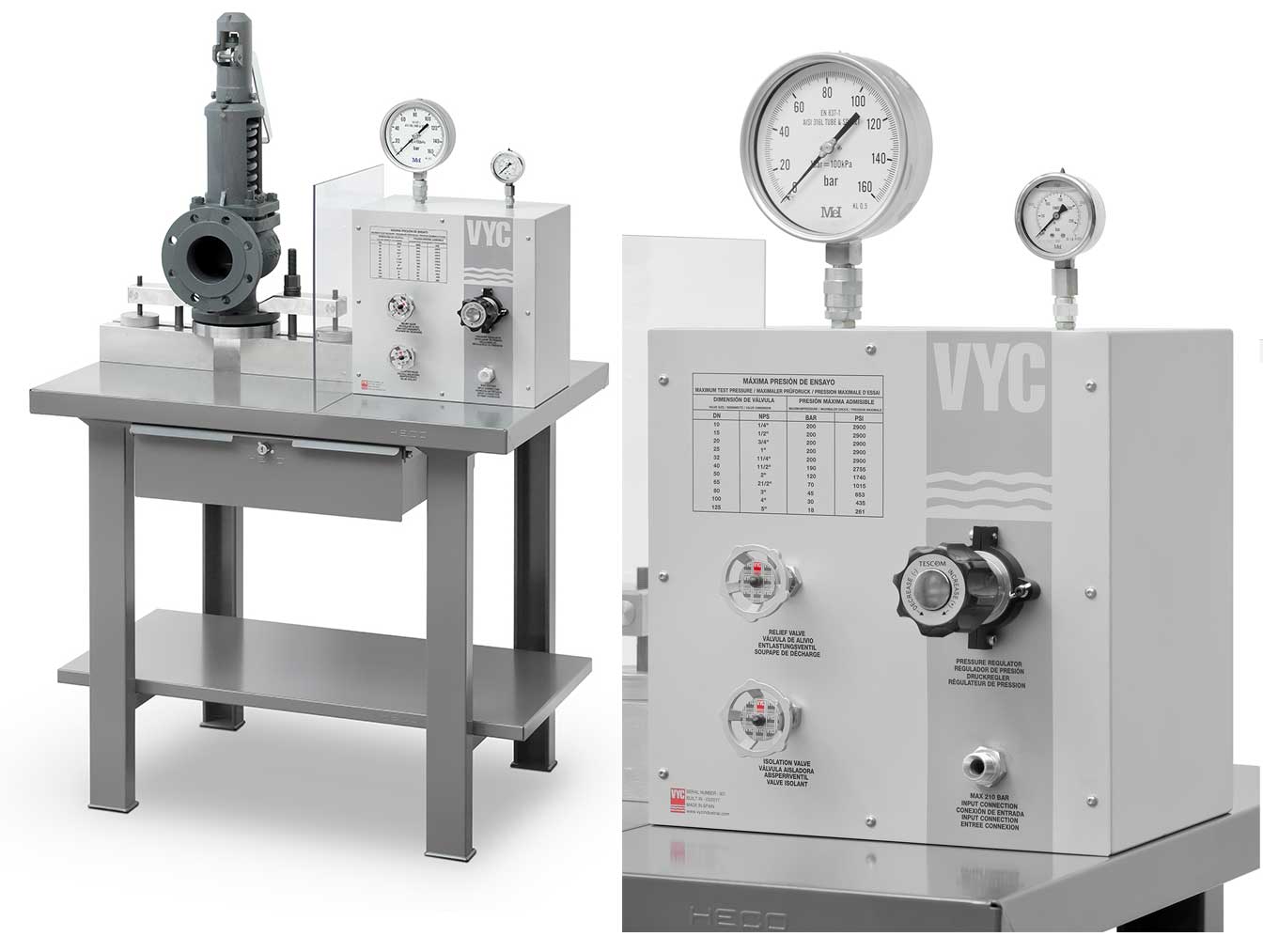
Test bench for regular inspections and setting and resetting safety valves. Ideal for distributors, maintenance companies or with in-house maintenance. It allows safety valves to be adjusted, tested and/or checked to the test pressure (setting) Pe wile cold (simulating service conditions), matching the opening pressure Ps and the closing pressure Pc, in accordance with the standard regulations.
Controlled safety pressure relief system CSPRS valves are mainly used where conventional direct-loaded spring action valves cannot guarantee the opening and closing margins that certain specifi c conditions of service demand.
The objective is to help the closure by means of pressure so that the valve remains completely watertight until reaching the set pressure and/or to activate the opening with pressure.
Increase the operating pressure of the system up to 99.9% of the set pressure.The control safety pressure relief system CSPRS device can be used with any safety valve available in the market and in particular, with models VYC Mod. 485, 486, 494, 495 and 496.
Stainless Steel Safety Relief Valve is a safety mechanism deployed in applications to prevent them from bursting under pressure. Suraj Metal Corporationis a leading manufacturer and supplier of the different types such as the Brass Safety Valveand others in various sizes and dimensions. The valves are fitted with the pipelines in a way that when the pressure goes above the threshold level, the Stainless Steel Air Safety Valveopens up and relieves the system of pressure.
This is important to prevent the pipes from being damaged or bursting under high pressure. The Stainless Steel Safety Exhaust Ball Valveis used in the exhaust systems where the temperature plays major role. When the temperature exceeds certain point, it increases pressure and the safety valve opens and balances the pressure in the system. The spring loaded boiler safety valveis used in boilers and heat exchanger systems where steam and hot water are circulated through pipes. There are different gas safety valvetypes and each of these differ in their purpose and functions. Please feel free to contact us for more information on the different types of air compressor pressure relief valveand others with pricing.
We Keep Bulk Stock of CF8 stainless steel Pressure Safety Valve at our stockyard, contact us for Free Sample & stock list, View Brass Safety Valve Dimension chart
find Stainless Steel Safety Exhaust Ball Valve Dimensions, price list, size chart here, Buy ASTM A351 CF8M 316 temperature safety valve at best price in India

The Popping Test or Pop Test is a set pressure test of Pressure Relief Valve (PRV). It is done by compressing air into the inlet of PRV until the valve opens. Engineers then compare the opening force with the set pressure of the PRV to see whether the valve functions as specified.
When pressure surpasses the safety threshold, relief valves pop off. The “popping off” action expels surplus pressure until the tank’s pressure drops to the designated minimum pressure. The valve then resets and closes automatically after completing the blowdown procedure.
Safety is imperative and test technicians should always behave as if the valve under pressure will physically implode at any moment. ASME Section I Division VIII covers testing criteria for pressure vessel and boiler applications. Other codes such as API may apply depending on the application.
Before testing, determine the set pressure of the PRV. Properly manufactured and serviced PRVs have a set pressure engraved on a tag that’s riveted onto the body. Ensure the gauge you’re using has the proper measuring range for the pressure you’ve set.
Reduce the pressure gradually and record the reseating pressure (the pressure at which the valve closes). This happens instantly if the pressure source contains too low of a volume, thus making the seating pressure too hard to record.
Even though the fundamental PRV testing technique is relatively straightforward, it produces results based on simple observation with minimal backing data. Provision of signed certifications allows for little to no traceability other than the technician’s word.
Always stay within the test stand’s pressure limits and ensure the test stand erects correctly. Ensure the valve’s escaping pressure directs away from the operator and that everyone in the test area wears safety shields and eye protection.
With this in mind, the application of pressure Relief Valves should be assigned only to fully trained personnel and strictly comply with rules provided by the governing codes and standards.
Bench testing provides the most popular type of pressure relief valve testing because it allows for work to occur in a controlled shop environment. Testing of valves that have already been in service, requires shutdown of the process system. Then, a lab takes receipt of the valve, checks it, and prepares it for testing.
An accurate pressure relief valve testing approach that does not need valve removal or facility downtime is inline testing. A competent technician can test valves in the system using inline safety relief valve testing equipment to determine the actual setpoint. Any testing that does not require bench testing may be a suitable candidate for inline pressure relief valve testing. It does away with the downtime requirement and delivers highly accurate results.
While not a popping test, all pressure relief valves require regular manual testing. An operated-in-place test occurs by manually activating the test lever on the valve. This ensures the valve can open and close tightly, but it does not validate its opening and closing pressure. This test requires quarterly or bi-annually to ensure the most basic functionality of safety relief valves.
The accumulation test is a boiler safety test that determines whether the safety valves can release steam quickly enough to keep the pressure rising by 10%. The main steam stop valve closes during this safety valve accumulation test. With the burner on, it validates that the steam pressure will not climb over 10% prior to the safety valve releasing excess steam pressure to the atmosphere.
Hydro testing, more formally called hydrostatic testing, is performed on pressure vessels to check for leaks. This testing completely fills a pressure vessel with water and pressures it. Once pressurized, leaks can be detected. Testing occurs in accordance with ASME Section VIII Division I.

At almost every show I attend, I ask a few engine owners and operators if they are satisfied with their new-style safety valves. It would be only a small exaggeration to say that I get just two responses. “I have been using a new-style valve for 15 years and I haven’t had any trouble with it” or “They are junk!” I have cleaned up the second response to spare the reader the unpleasant expletives.
As the result of these conversations, I have attempted to understand why there is such a discrepancy between the reactions to modern safety valves. It now appears that there are a few simple steps we can take when purchasing and installing these valves that might improve our satisfaction with the new-style valves, which are the only ones currently available.
To understand the issues involved in the selection of a safety valve, it is necessary to review the history of safety valves used on hand-fired boilers. I am referring to hand-fired boilers rather than historical boilers because the issues are determined by how the boilers are fired, not how they are constructed or how old they are. The requirements for a modern welded boiler made to the American Society of Mechanical Engineers (ASME) code are the same as for a 100-year-old riveted boiler, if both boilers are hand-fired. The requirements for a safety valve for a boiler that is automatically fired are dramatically different.
With automatic firing, the safety valve’s function as defined by Anderson Greenwood Crosby, a manufacturer of modern safety valves, is to protect life and property if all other safety measures fail. A safety valve on a hand-fired boiler, as defined by ASME almost a hundred years ago, is to give notice of the highest pressure permissible and to give alarm that more water or less fuel is needed. (The evolution of the purpose of the safety valve is summarized in “The Purpose of a Safety Valve,” at the end of this article.)
When hand-fired boilers, such as found on traction engines, steam cranes and locomotives disappeared, most of the boilers that remained were automatically fired. The safety valve manufacturers adapted their designs accordingly. The old-style valves with bottom guided, beveled seats were capable of withstanding vibration and operating near their setpoint, and were replaced by smaller top-guided valves with flat seats.
At the same time, steam system designs were adapted so there was no need to operate within 10 percent of the setpoint of the safety valve. Not all old-style valves had beveled seats, but the ones that didn’t were designed much differently from the modern flat-seated valves.
When I speak of a modern-style safety valve, I am referring to a valve shown in the second diagram of this article’s image gallery. An example of an old-style safety valve can also be seen in the image gallery. Changes in the design of safety valves had a dramatic effect on their capacity in pounds of steam per hour. If a boiler built in 1920 required a valve capable of releasing 1,000 pounds of steam per hour at a pressure of 100 pounds per square inch, it would have been equipped with a 2-inch safety valve. Today, 3/4-inch valves are available to release that much steam at that pressure.
The evolution of the safety valve did not end with the development of the modern, flat-seated valve. In the last 20 years, the design of safety valves has continued to evolve.
In 1985, a new-style 3/4-inch valve set at 150 pounds per square inch could have a capacity of 1,497 pounds of steam per hour. In 2002 this same valve could have a capacity of 1,651 pounds of steam per hour.
From 1914 until 1998, the blowdown allowed by the ASME boiler code was 2 to 4 percent of the setpoint. In 1998, this was changed to allow the blowdown to be as high as 6 percent. Beginning with the 2004 ASME code, there is no limit on blowdown. The code has not required that the amount of blowdown be stamped on a safety valve since 1986.
When I asked owners and operators how well they liked their new-style safety valves, I was not aware of the need to ask about the age of the valve. Instead, I would ask about the amount of blowdown. In almost every case, the people who were satisfied had valves that would blowdown 4 percent or less. It appears that this is almost the same as if I had asked the age of the valve. If the valve were purchased prior to 1998, it would have been set for 4 percent blowdown. If purchased after that date, unless specified otherwise, it would have been set for 6 percent. The change from 4 to 6 percent causes a 50 percent increase in the amount the pressure changes in a boiler each time the valve pops. The resulting increase in the flexing of the components of the boiler may be associated with a corresponding increase in seepage at stay bolts and tubes.
When you order a new safety valve, you will need to provide four pieces of information: the setpoint, the capacity in pounds of steam per hour, the blowdown and the requirement that the valve be stamped with the ASME “V” stamp. If you specify the pipe size, you may get a valve with far too much capacity, as I have already explained. To determine the capacity you need, do not use the capacity stamped on the old valve. First, if the valve has been replaced, it might not be the right capacity. Secondly, the capacity stamped on the valve is probably the capacity of the smallest valve available and might be significantly larger than the required capacity.
Calculating the heating surface of the boiler, in square feet, and multiplying the number by a factor can determine the required capacity. The ASME code requires a factor of 5 pounds of steam per hour per square foot of heating surface. Ohio requires a factor of 7. The heating surface is the area above the grates that is exposed to the fire. This includes the firebox, the tubes and the front tube sheet.
As I talked to many owners, they would offer other comments regarding their valves. One comment I heard from several owners who were satisfied with the new-style valves was that their valves were larger in pounds per hour than the minimum required by the ASME code. I am not certain as to exactly how the capacity affects the operation of the valve. What I do know is the larger the valve, the more force it takes to raise it off its seat. The force of the steam on the boiler-side of the valve cannot overcome the force of the spring in the safety valve until the pressure in the boiler rises to the setpoint of the valve.
When this happens, the valve pops open. It seems the larger diameter, and thus the greater forces, may result in more stable operation of the valve near its setpoint. There is a concern in the boiler code that safety valves should not be so large that water is drawn out of the boiler. It would seem, because of the relatively small size of portable and traction boilers, the pressure would drop so quickly that little water, if any, would be lost. I have seen boilers where the owners have installed modern safety valves of the same pipe size as the old style valves installed by the factory. The capacity of these valves was far greater than I believe anyone would recommend, but I am not aware that they caused water to be discharged from the boiler. It is important to be careful when sizing a safety valve. I suggest owners talk to each other and share their experiences before making such a decision.
If you would prefer to have a top-discharge safety valve, which looks more authentic, shop around. They are available in a few sizes. You might also want to consider specifying that the valve have a non-metallic seat.
When installing a safety valve, do not install any fitting smaller than the inlet to the valve and do not install any kind of valve between the safety valve and the boiler. Examples of what not to do can be seen in the image gallery. Do not use a pipe wrench on a safety valve, it can damage or destroy the valve.
Once you have carefully selected your safety valve and have installed it on your boiler, it is important to verify the setpoint and the blowdown have been set according to your specifications. The first step in this process is to have the accuracy of your steam gauge checked with a dead-weight gauge tester. If your gauge does not agree with the setpoint of your new safety valve do not assume that the gauge is wrong.
Do not use the lifting lever to lift the valve from its seat until the boiler pressure is up to 75 percent of the setpoint of the valve. If the valve is lifted from its seat at a lower pressure, any dirt or foreign material in the valve might not be blown clear of the seat and could damage the seats when the valve closes.
Because new-style safety valves are not designed to be operated within 10 percent of their setpoint, many owners have elected to install the new valve along with an old-style valve. In doing so, the old style valve operates in the range of 5 to 10 percent below the setpoint of the new valve. With this arrangement, the new valve satisfies the code requirements while the old-style valve performs the function for which it was designed. Two possible arrangements can be seen in the image gallery.
In response to complaints from owners of historical boilers who had recently purchased new safety valves, Dean Jagger, Ohio’s chief boiler inspector, requested that the National Board test valves from the manufacturer to determine if the valves complied with the requirements of the ASME boiler code. As a result of these tests the Ohio Department of Commerce issued a safety notice:
“The State of Ohio Boiler Division has been made aware of the fact that some recently purchased Kunkle safety valves, which were assembled by Allied Industries, have been tested by the National Board Testing Laboratory and found not to be in compliance. The tests indicated that the valves blowdown and setpoint pressure settings were out of tolerance as established by Section I of the ASME Boiler Code.”
This may be an indication that all of the problems with modern safety valves are not entirely the result of design issues, but insufficient oversight of manufacturing and quality control processes may also be a factor. A new valve may be “junk” as has been so often alleged.
The errors found by the National Board Laboratories were significant. One of the valves was stamped 165 psi but popped low at 148.8 psi. Another was stamped 150 psi and popped high at 164.5 psi. On the other three valves the pop was consistent with the setting stamped on the valve. The 2001 edition of the ASME Boiler Code specifies that for pressures from 70 to 300 psi the tolerance, plus or minus from the set pressure, shall not exceed 3 percent of the set pressure. The 165 psi valve popped 9.6 percent below the set pressure stamped on the valve, and the 150 psi valve popped 9.7 percent above the set pressure stamped on the valve.
The blowdowns on all of the valves that were tested were out of tolerance. The 2001 edition of the ASME Boiler Code specifies that for pressures from 67 to 250 psi the blowdown shall not be greater than 6 percent of the set pressure. With such a wide range of variations in both setpoint and blowdown, in a sample of just five valves, it seems reasonable to suspect that even greater variations may exist. The results of the tests are shown in the image gallery.
Complaints about quality problems are not limited to the five valves recently tested by the National Board; for example, an engine owner told me of purchasing a new 1-1/4-inch valve stamped 175 psi. When installed on a traction engine, the valve consistently popped at 185 psi and blew down 15 psi. (A pressure of 11.1 psi equals the allowed 6 percent.) The manufacturer told the owner that the valve had been tested properly prior to shipment but accepted it back. The owner had verified the accuracy of the pressure gauge prior to contacting the manufacturer.
The ASME and National Board procedures for safety valves merely confirm the adequacy of the design of the valve and do not assure the adequacy of production and quality control practices. Each boiler owner and operator must carefully confirm the accuracy of the setpoint and blowdown on every safety valve and not rely on the ASME and National Board stamps as assurances of quality. At this time, I have no reason to believe the monitoring of the ASME and National Board requirements at other valve manufacturers and assemblers is any different than what existed at Kunkle and Allied.
One scenario that concerns me is the owner who installs a new safety valve on his boiler and, seeing that the pop does not coincide with the reading on his 80- or 100-year-old gauge, decides that obviously his gauge must be wrong. This is a conclusion I am sure I would have considered when I first began my study of safety valves.
Incorrect settings of safety valves are more likely to be detected when the valves are used on hand-fired boilers than when used on modern boilers. If the controls on a modern boiler are to limit the pressure to 10 percent or more below the setpoint of the safety valve, the valve can be set as much as 10 percent below its rating and the error might not be apparent. Errors above the setpoint also wouldn’t be obvious even if the boiler were operated up to the setpoint stamped on the valve. Also, incorrect setting of the blowdown would not be apparent until the valve had operated.
1909: “The function of the safety valve is two fold: (A) it gives notice of the highest pressure permissible; (B) it gives alarm that more water or less fuel is needed.”
Today: “A PRV (pressure relief valve) is a safety device intended to protect life and property if all other safety measures fail.” – Anderson Greenwood Crosby, 2001 (safety valve manufactuer)
Bob Ferrell, Bob Schuler and Fred Harrison of the National Board of Boiler and Pressure Vessel Inspectors were instrumental in helping to obtain the information from the old editions fo the ASME boiler codes. Their assistance is greatly appreciated.

Choose these valves for small steam-heating boilers requiring pressure relief between 5 psi and 12 psi. They spring fully open at the set pressure and remain open until the system pressure is restored below the set pressure. All have a bronze body for durability and a long service life.

Boiler contractors see these valves all the time when working on equipment. Generally the steam relief valve is often little understood, often incorrectly installed, and usually neglected. A little refresher on these valves might be in order.
As the pressure of the steam within a boiler approaches the set pressure of the valve, the steam pressure on the underside of the actuating disc approaches the pressure of a spring applied to the outer side of the disc. When equilibrium is passed, the disc starts to lift off its seat. The moment this happens, steam is suddenly released all around the disc to what is called the “huddling chamber.” This chamber increases the area of the disc that sees steam pressure, thus increasing force. This increased area under steam pressure makes the pressure much more unbalanced in the direction of the valve discharge opening and therefore pops the valve into a wide open position. When the valve opens with a “pop” the valve seat is preserved from wiredraw caused by slow opening.
Closure of the valve occurs only after the boiler pressure is dropped several pounds below the set point. The reduction of the area of the disc seeing steam causes the disc to firmly close against the valve seat.
The first area of concern is valve distortion. Valve distortion occurs when the valve is improperly wrenched in, using the valve body instead of supplied wrench flats. Distortion also occurs when the discharge side of the safety relief valve is made to bear the weight of the discharge piping. To prevent this distortion use a short nipple from the valve to an independently supported bell reducer or drip pan elbow. These valves are precision devices and any distortion will affect accuracy and calibration.
The second area of concern is discharge piping. For a safety valve to do its job it must be sized properly to adequately relieve all the steam the boiler is capable of producing while operating at its maximum. All piping to or from a safety relief valve must be at least as large as the valve’s connections. Also, the restrictive effect of elbows and the friction losses in pipe must be taken into account. For this reason, piping runs should be as short as possible and pipe sizes should be generous.
If you need help in replacing or sizing a steam relief valve please contact Stromquist and Company at 1-800-241-9471. All others can order this product from one of our affiliates at CGNA.

Relief and safety Valves are used in high pressure systems to control the pressure and keep balance of the system. The different between safety valves and relief valves is that the safety valves fully open or close under a certain pressure while the relief valves can open in proportion to the pressure in front of them. The safety and pressure relief valves are used automatically. They both operate under similar conditions. When the pressure builds up in a system, it has to be managed by releasing the material to flow through. These valves have a threshold pressure at which they open. The consolidated safety and safety relief valves comprise of a bonnet vent and bellow with springs.
The springs are set up for the threshold pressure and when the pressure exceeds the threshold, the spring is pushed into the bonnet vent and the bellow opens the valve. The Safety Relief Valves can be open and shut valves. They either open or shut off at any given pressure. This is mostly for the safety of an application not to explode under high pressure. The Pressure Relief Valve on the other hand releases the material after the threshold pressure, but not fully. If the pressure is slightly higher the threshold, then the valve opens slightly. If the pressure is very high above the threshold, it opens wider. It also functions in the same manner when the pressure drops down. The valve closes in proportion to the pressure. The safety valve shuts down at once only when the pressure is below the threshold.
Ready Stock of ASTM A351 CF8M Spring Loaded Safety Valve in wide range of Sizes, Stainless Steel Air Compressor Pressure Relief Valve Manufacturers In India
Relief Valves are designed to control pressure in a system While Safety Valves are used for controlling the pressure in a system they release pressure immediately in the event of an emergency or system failure
The Setpoint of relief valve is usually set at 10 Percent above working pressure limit while safety valve is usually set at 3% above working pressure limit.
If you are operating systems that can only be off for short periods of time, it is sensible to keep a spare valve to swap over and then the removed valve can be inspected and recertified.

The PSV (Pressurizer Safety Valve) popping test carried out practically in the early phase of a refueling outage has a little possibility of triggering a test-induced LOCA due to a PSV not fully closed or stuck open. According to a KSNP (Korea Standard Nuclear Power Plant) low power and shutdown PSA (Probabilistic Safety Assessment), the failure of a HPSI (High Pressure Safety Injection) following a PSV stuck open was identified as a dominant accident sequence with a significant contribution to low power and shutdown risks. In this study, we aim to investigate the consequences of the NPP for the various accident sequences following the PSV stuck open as an initiating event through the thermal-hydraulic system code calculations. Also, we search the accident mitigation method for the sequence of HPSI failure, then, the applicability of the method is verified by the simulations using T/H system code.
The paper presents the results of the independent analysis of the operational event which took place on 07.11.2003 at Unit 1 of Rostov NPP. The event started with switching off the electrical generator of the turbine due to a short cut at the local switching substation. The turbine isolating valves closed to prevent damage of the turbine. The condenser dump valves (BRU-K) and the atmospheric dump valves (BRU-A) opened to release the vapour generated in the steam generators. After the pressure decrease in the steam generators BRU-K and BRU-A closed but one valve stuck opened. The emergency core cooling system was activated automatically. The main circulation pump of the loop corresponding to the steam generator with the stuck BRU-A was tripped. The stuck valve was closed by the operational stuff manually. No safety limits were violated. The analysis of the event was carried out using ATHLET code. A reasonable agreement was achieved between the calculated and measured values. (author)
In PWR steam generator tube rupture (SGTR) faults, a direct pathway for the release of radioactive fission products can exist if there is a coincident stuck-open safety relief valve (SORV) or if the safety relief valve is cycled. In addition to the release of fission products from the bulk steam generator water by moisture carryover, there exists the possibility that some primary coolant may be released without having first mixed with the bulk water - a process called primary coolant bypassing. The MB-2 Phase II test program was designed specifically to identify the processes for droplet carryover during SGTR faults and to provide data of sufficient accuracy for use in developing physical models and computer codes to describe activity release. The test program consisted of sixteen separate tests designed to cover a range of steady-state and transient fault conditions. These included a full SGTR/SORV transient simulation, two SGTR overfill tests, ten steady-state SGTR tests at water levels ranging from very low levels in the bundle up to those when the dryer was flooded, and three moisture carryover tests without SGTR. In these tests the influence of break location and the effect of bypassing the dryer were also studied. In a final test the behavior with respect to aerosol particles in a dry steam generator, appropriate to a severe accident fault, was investigated
Highlights: ► We modelled the ASTEC input file for accident scenario (SBO) and focused analyses on the behaviour of core degradation. ► We assumed opening and stuck-open of pressurizer relief valve during performance of SBO scenario. ► ASTEC v1.3.2 has been used as a reference code for the comparison study with the new version of ASTEC code. - Abstract: The objective of this paper is to present the results obtained from performing the calculations with ASTEC computer code for the Source Term evaluation for specific severe accident transient. The calculations have been performed with the new version of ASTEC. The ASTEC V2 code version is released by the French IRSN (Institut de Radioprotection at de surete nucleaire) and Gesellschaft für Anlagen-und Reaktorsicherheit (GRS), Germany. This investigation has been performed in the framework of the SARNET2 project (under the Euratom 7th framework program) by Institute for Nuclear Research and Nuclear Energy – Bulgarian Academy of Science (INRNE-BAS).
A safety injection event happened by opening of the Main Steam Safety Valve at Kori unit 1 on April 16, 2005. The safety valves were opened at the lower system pressure than the valve opening set point due to rapid system pressure drop by opening of the Power Operated Relief Valve installed at the upstream of the Main Steam System. But the opening mechanism of safety valve at the lower set point pressure was not explained exactly. So, it needs to be understood about the safety valve opening mechanism to prevent a recurrence of this kind of event at a similar system of Nuclear Power Plant. This study is aimed to suggest the hydrodynamic mechanism for the safety valve opening at the lower set point pressure and the possibility of the recurrence at similar system conditions through document reviewing for the related previous studies and Kori unit 1 event
Full Text Available BACKGROUND Implantation of prosthetic cardiac valves to treat haemodynamically significant valvular diseases has become common; however, it is associated with complications. Thus, this study was intended to evaluate the indications for implantation of prosthetic valve and complications after its implantation and prognosis after treatment of one of its complication, i.e. stuck valve. MATERIALS AND METHODS This was a single-centered study wherein 50 patients who came to the emergency department with stuck valve were assessed. The 2D echocardiography was performed in all patients. Thrombolysis was done and the gradients were reassessed. Further response to treatment and development of complications before and after treatment were observed. RESULTS Of total patients, 60% were females. Mean age group was 30-40 yrs. Most of them were asymptomatic for 6 years and there was lack of compliance in 90% of patients. Most common indication for valve replacement was mitral stenosis (60% followed by mitral regurgitation (20%, aortic regurgitation and aortic stenosis (10% and combined mitral and tricuspid regurgitation (10%. Commonest valve was St. Jude (90%. Pannus was observed in 10% patients and thrombus was observed in 50% patients. Most patients had gradients 45/20 mmHg across mitral valve. In about 90% patients, gradients decreased after thrombolysis (12/5 mmHg. The complications after thrombolysis were hemiparesis (4%, death before thrombolysis (6% and death after thrombolysis (4%. CONCLUSION Considering these results, it can be concluded that prosthetic valves are seldom associated with some complications. Further, thrombolysis can be effective in patients with prosthetic valve thrombosis.
Purpose: To enable the detection of the closing of a safety valve when the internal pressure in a BWR type reactor is a value which will close the safety valve, by inputting signals from a pressure detecting device mounted directly at a reactor vessel and a safety valve discharge pressure detecting device to an AND logic circuit. Constitution: A safety valve monitor is formed of a pressure switch mounted at a reactor pressure vessel, a pressure switch mounted at the exhaust pipe of the escape safety valve and a logic circuit and the lide. When the input pressure of the safety valve is raised so that the valve and the pressure switch mounted at the exhaust pipe are operated, an alarm is indicated, and the operation of the pressure switch mounted at a pressure vessel is eliminated. If the safety valve is not reclosed when the vessel pressure is decreased lower than the pressure at which it is to be reclosed after the safety valve is operated, an alarm is generated by the logic circuit since both the pressure switches are operated. (Sekiya, K.)
After the TMI event efforts were aimed towards improvements in the operational and administrative procedures related to the power operated relief valves (PORVs) in order to decrease the probability of a small-break loss-of-coolant accident (LOCA) caused by stuck-open power operated relief valve. This paper presents a frequency probabilistic analysis of a small break LOCA due to a stuck open PORV and safety valve to the Angra I nuclear power plant in operating conditions pre-TMI and post-TMI. (Author) [pt
... 46 Shipping 2 2010-10-01 2010-10-01 false Opening between boiler and safety valve (modifies PFT-44). 52.20-17 Section 52.20-17 Shipping COAST GUARD, DEPARTMENT OF HOMELAND SECURITY (CONTINUED) MARINE ENGINEERING POWER BOILERS Requirements for Firetube Boilers § 52.20-17 Opening between boiler and safety valve...
The blowdown of a spring loaded safety valve is defined as the difference between the pressure at which the valve opens and the pressure at which the valve fully closes under certain fluid flow conditions. Generally, the blowdown is expressed in terms of percentage of the opening pressure. An extensive series of tests carried out in the EPRI/PWR Utilities Valve Test Program has shown that the blowdown of safety valves can in general be strongly dependent upon the valve geometry and other parameters such as ring adjustments, spring stiffness, backpressure etc. In the present study, correlations have been developed using the EPRI safety valve test data to predict the expected blowdown as a function of adjustment ring settings for geometrically similar valves under steam discharge conditions. The correlation is validated against two different size Dresser valves
In performing the safety analyses for transients that result in a challenge to the reactor coolant system (RCS) pressure boundary, the general acceptance criterion is that the peak RCS pressure not exceed the American Society of Mechanical Engineers limit of 110% of the design pressure. Without crediting non-safety-grade pressure mitigating systems, protection from this limit is mainly provided by the primary and secondary code safety valves. In theory, the combination of relief capacity and setpoints for these valves is designed to provide this protection. Generally, banks of valves are set at varying setpoints staggered by 15- to 20-psid increments to minimize the number of valves that would open by an overpressure challenge. In practice, however, when these valves are removed and tested (typically during a refueling outage), setpoints are sometimes found to have drifted by >50 psid. This drift should be accounted for during the performance of the safety analysis. This paper describes analyses performed by Yankee Atomic Electric Company (YAEC) to account for setpoint drift in safety valves from testing. The results of these analyses are used to define safety valve operability or acceptance criteria
... gov/ency/article/007408.htm Aortic valve surgery - open To use the sharing features on this page, ... separates the heart and aorta. The aortic valve opens so blood can flow out. It then closes ...
Two different flow areas discharge same amount of design steam flow at the design condition but they provide the different flow rate during low pressure condition or two-phase mixture discharge. To evaluate the effect of the H-F model modification, the PSV stuck open event during a PSV popping test is selected since it involves the two phase discharge. In the present PSA practice for dealing with the variety of different plant operating states (POSs) during low power and shutdown (LPSD) operations, especially PSV popping test is performed during the POS2 of the overhaul period for OPR1000. To analyze thermal hydraulic behaviors of PSV stuck open event during POS2, RELAP5/MOD3.3 is used adopting the H-F critical flow model. In this paper, the impact on the PSV stuck open analysis during POS2 according to H-F critical flow model modification is investigated. Due to the modification of H-F model in RELAP5/MOD3.3 patch 4, the critical steam flow rate is increased at high pressure and thus the simulated PSV area is decreased. The change in PSV flow area impacts on the thermal hydraulic behaviors of the PSV stuck open event during POS2. PSA modeling can be changed depending on the results of thermal hydraulic analysis.
Two different flow areas discharge same amount of design steam flow at the design condition but they provide the different flow rate during low pressure condition or two-phase mixture discharge. To evaluate the effect of the H-F model modification, the PSV stuck open event during a PSV popping test is selected since it involves the two phase discharge. In the present PSA practice for dealing with the variety of different plant operating states (POSs) during low power and shutdown (LPSD) operations, especially PSV popping test is performed during the POS2 of the overhaul period for OPR1000. To analyze thermal hydraulic behaviors of PSV stuck open event during POS2, RELAP5/MOD3.3 is used adopting the H-F critical flow model. In this paper, the impact on the PSV stuck open analysis during POS2 according to H-F critical flow model modification is investigated. Due to the modification of H-F model in RELAP5/MOD3.3 patch 4, the critical steam flow rate is increased at high pressure and thus the simulated PSV area is decreased. The change in PSV flow area impacts on the thermal hydraulic behaviors of the PSV stuck open event during POS2. PSA modeling can be changed depending on the results of thermal hydraulic analysis
In Korean 3 Loop plants a water loop seal pipe is installed containing condensed water upstream of a pressurizer safety valve to protect the valve disk from the hot steam environment. The loop seal water purge time is a key parameter in safety analyses for overpressure transients, because it delays valve opening. The loop seal purge time is uncertain to measure by test and thus 3-dimensional realistic computational fluid dynamics (CFD) model is developed in this paper to predict the seal water purge time before full opening of the valve which is driven by steam after water purge. The CFD model for a typical pressurizer safety valve with a loop seal pipe is developed using the computer code of ANSYS CFX 11. Steady-state simulations are performed for full discharge of steam at the valve full opening. Transient simulations are performed for the loop seal dynamics and to estimate the loop seal purge time. A sudden pressure drop higher than 2,000 psia at the tip of the upper nozzle ring is expected from the steady-state calculation. Through the transient simulation, almost loop seal water is discharged within 1.2 second through the narrow opening between the disk and the nozzle of the valve. It can be expected that the valve fully opens at least before 1.2 second because constant valve opening is assumed in this CFX simulation, which is conservative because the valve opens fully before the loop seal water is completely discharged. The predicted loop seal purge time is compared with previous correlation. (orig.)
In Korean 3 Loop plants a water loop seal pipe is installed containing condensed water upstream of a pressurizer safety valve to protect the valve disk from the hot steam environment. The loop seal water purge time is a key parameter in safety analyses for overpressure transients, because it delays valve opening. The loop seal purge time is uncertain to measure by test and thus 3-dimensional realistic computational fluid dynamics (CFD) model is developed in this paper to predict the seal water purge time before full opening of the valve which is driven by steam after water purge. The CFD model for a typical pressurizer safety valve with a loop seal pipe is developed using the computer code of ANSYS CFX 11. Steady-state simulations are performed for full discharge of steam at the valve full opening. Transient simulations are performed for the loop seal dynamics and to estimate the loop seal purge time. A sudden pressure drop higher than 2,000 psia at the tip of the upper nozzle ring is expected from the steady-state calculation. Through the transient simulation, almost loop seal water is discharged within 1.2 second through the narrow opening between the disk and the nozzle of the valve. It can be expected that the valve fully opens at least before 1.2 second because constant valve opening is assumed in this CFX simulation, which is conservative because the valve opens fully before the loop seal water is completely discharged. The predicted loop seal purge time is compared with previous correlation. (orig.)
... 49 Transportation 4 2010-10-01 2010-10-01 false Safety valves. 229.109 Section 229.109..., DEPARTMENT OF TRANSPORTATION RAILROAD LOCOMOTIVE SAFETY STANDARDS Safety Requirements Steam Generators § 229.109 Safety valves. Every steam generator shall be equipped with at least two safety valves that have a...
This report presents analysis of development emergency operating procedures effectiveness for possible accident on nuclear power plant with WWER-1000 reactor type. Accident initiating event is the primary to secondary circuit leak caused by steam generator primary cover lift-up. In according to conservative assumptions the following additional failures were considered: dump valve BRU-A stuck open failure; loss of external power. The results of this work are represented as a comparative analysis of two possible ways of accident evolution: according to functioning automatic safety systems responses; according to accident management based on development emergency operating procedures with operator intervention. Developed emergency operating procedures assure the following significant goals to mitigate accident sequences: optimal use of ECCS water inventory; severe core damage prevention; mitigation of environment radioactive contamination. (authors)
This paper reports that Conoco Pipeline is using a unique relief valve to reduce costs while improving environmental protection at its facilities. Conoco Pipeline Co. Inc. began testing new relief valves in 1987 to present over-pressuring its pipelines while enhancing the safety, environmental integrity and profitability of its pipelines. Conoco worked jointly with Rupture Pin Technology Inc., Oklahoma City, to seek a solution to a series of safety, environmental, and operational risks in the transportation of crude oil and refined products through pipelines. Several of the identified problems were traced to a single equipment source: the reliability of rupture discs used at pipeline stations to relieve pressure by diverting flow to tanks during over-pressure conditions. Conoco"s corporate safety and environmental policies requires solving problems that deal with exposure to hydrocarbon vapors, chemical spills or the atmospheric release of fugitive emissions, such as during rupture disc maintenance. The company had used rupture pin valves as vent relief devices in conjunction with development by Rick Austin of inert gas methods to protect the inner casing wall and outer carrier pipeline wall in pipeline road crossings. The design relies on rupture pin valves set at 5 psi to isolate vent openings from the atmosphere prior to purging the annular space between the pipeline and casing with inert gas to prevent corrosion. Speciality Pipeline Inspection and Engineering Inc., Houston, is licensed to distribute the equipment for the new cased-crossing procedure
By the nature of its design, the set point and lift of a conventional spring loaded safety relief valve are sensitive to back pressure. One way to reduce the adverse effects of the back pressure on the safety relief valve function is to install a balanced bellows in a safety relief valve. The metallic bellows has a rather wide range of manufacturing tolerance which makes the design of the bellows safety relief valve very complicated. The state-of-the-art balanced bellows safety relief valve can only substantially minimize, but cannot totally eliminate the back pressure effects on its set point and relieving capacity. Set point change is a linear function of the back pressure to the set pressure ratio. Depending on the valve design, the set point correction factor can be either greater or smaller than unity. There exists an allowable back pressure and critical back pressure for each safety relief valve. When total back pressure exceeds the R a , the relieving capacity will be reduced mainly resulting from the valve lift being reduced by the back pressure and the capacity reduction factor should be applied in valve sizing. Once the R c is exceeded, the safety relief valve becomes unstable and loses its over pressure protection capability. The capacity reduction factor is a function of system overpressure, but their relationship is non-linear in nature. (orig.)
A study of the modeling techniques adequate for simulating the loss of coolant accident caused by stuck open pressurizer relief valves, using the RELAP4-MOD5 code, is performed and the model developed is applied to the analysis of this kind of accident for the Central Nuclear Almirante Alvaro Alberto Unit (Angra 1). The thermal hydraulic behavior of the reactor cooling system, when subjected to a loss of main feedwater followed by the failure in the open position of two pressurizer relief valves, is determined. The relief valves are assumed to fail in the totally open position, delivering the maximum massflow through the discharge line. The RELAP4-MOD5 code is shown to be adequate for this kind of analysis, and the detailed prediction of the thermal hydraulic behavior of the Reactor Coolant System is thus possible. The eficiency of the emergency core cooling system of Angra 1 is demonstrated, the fuel elements remaining covered by the coolant during all the accident, and the peak clad temperatures are kept within design limites, ensuring the integrity of the core. (Author) [pt
The Safety Valve Handbook is a professional reference for design, process, instrumentation, plant and maintenance engineers who work with fluid flow and transportation systems in the process industries, which covers the chemical, oil and gas, water, paper and pulp, food and bio products and energy sectors. It meets the need of engineers who have responsibilities for specifying, installing, inspecting or maintaining safety valves and flow control systems. It will also be an important reference for process safety and loss prevention engineers, environmental engineers, and plant and process designers who need to understand the operation of safety valves in a wider equipment or plant design context. . No other publication is dedicated to safety valves or to the extensive codes and standards that govern their installation and use. A single source means users save time in searching for specific information about safety valves. . The Safety Valve Handbook contains all of the vital technical and standards informat...
How to set policy in the presence of uncertainty has been central in debates over climate policy. Concern about costs has motivated the proposal for a cap-and-trade program for carbon dioxide, with a "safety valve" that would mitigate against spikes in the cost of emission reductions by introducing additional emission allowances into the market when marginal costs rise above the specified allowance price level. We find two significant problems, both stemming from the asymmetry of an instrument that mitigates only against a price increase. One is that most important examples of price volatility in cap-and-trade programs have occurred not when prices spiked, but instead when allowance prices collapsed. Second, a single-sided safety valve may have unintended consequences for investment. We illustrate that a symmetric safety valve provides environmental and welfare improvements relative to the conventional one-sided approach.
The LOFT pressurizer self-actuating safety-relief valves are constructed to the present state-of-the-art and should have reliability equivalent to the valves in use on PWR plants in the U.S. There have been no NRC incident reports on valve failures to lift that would challenge the Technical Specification Safety Limit. Fourteen valves have been reported as lifting a few percentage points outside the +-1% Tech. Spec. surveillance tolerance (9 valves tested over and 5 valves tested under specification). There have been no incident reports on failures to reseat. The LOFT surveillance program for assuring reliability is equivalent to nuclear industry practice.
The LOFT pressurizer self-actuating safety-relief valves are constructed to the present state-of-the-art and should have reliability equivalent to the valves in use on PWR plants in the U.S. There have been no NRC incident reports on valve failures to lift that would challenge the Technical Specification Safety Limit. Fourteen valves have been reported as lifting a few percentage points outside the +-1% Tech. Spec. surveillance tolerance (9 valves tested over and 5 valves tested under specification). There have been no incident reports on failures to reseat. The LOFT surveillance program for assuring reliability is equivalent to nuclear industry practice
The pressurizer relief and safety valve system provides the reactor coolant system overpressure protection and, therefore, it is fundamental for the security of a nuclear plant. This paper discusses the safety valve loop seal strategies adopted by others nuclear power plants over the world in order to attend the recommendations of NUREG-0578 (TMI-2 Lessons Learned Task Force Status Report and Short Term Recommendations). The technical option adopted for Angra 1 consists in making specific modifications on the original piping and support configuration of the pressurizer relief and safety valve system. These modifications were proposed in order to reduce the high stress levels induced by the thermal-hydrodynamic loads caused by the discharge of the sub-cooled water during the opening of the relief or the safety valves. Several thermal-hydraulic models were tested to assess the influen


 8613371530291