
boiler safety valve regulations quotation

Boiler explosions have been responsible for widespread damage to companies throughout the years, and that’s why today’s boilers are equipped with safety valves and/or relief valves. Boiler safety valves are designed to prevent excess pressure, which is usually responsible for those devastating explosions. That said, to ensure that boiler safety valves are working properly and providing adequate protection, they must meet regulatory specifications and require ongoing maintenance and periodic testing. Without these precautions, malfunctioning safety valves may fail, resulting in potentially disastrous consequences.
Boiler safety valves are activated by upstream pressure. If the pressure exceeds a defined threshold, the valve activates and automatically releases pressure. Typically used for gas or vapor service, boiler safety valves pop fully open once a pressure threshold is reached and remain open until the boiler pressure reaches a pre-defined, safe lower pressure.
Boiler relief valves serve the same purpose – automatically lowering boiler pressure – but they function a bit differently than safety valves. A relief valve doesn’t open fully when pressure exceeds a defined threshold; instead, it opens gradually when the pressure threshold is exceeded and closes gradually until the lower, safe threshold is reached. Boiler relief valves are typically used for liquid service.
There are also devices known as “safety relief valves” which have the characteristics of both types discussed above. Safety relief valves can be used for either liquid or gas or vapor service.
Nameplates must be fastened securely and permanently to the safety valve and remain readable throughout the lifespan of the valve, so durability is key.
The National Board of Boiler and Pressure Vessel Inspectors offers guidance and recommendations on boiler and pressure vessel safety rules and regulations. However, most individual states set forth their own rules and regulations, and while they may be similar across states, it’s important to ensure that your boiler safety valves meet all state and local regulatory requirements.
The National Board published NB-131, Recommended Boiler and Pressure Vessel Safety Legislation, and NB-132, Recommended Administrative Boiler and Pressure Vessel Safety Rules and Regulationsin order to provide guidance and encourage the development of crucial safety laws in jurisdictions that currently have no laws in place for the “proper construction, installation, inspection, operation, maintenance, alterations, and repairs” necessary to protect workers and the public from dangerous boiler and pressure vessel explosions that may occur without these safeguards in place.
The documents are meant to be used as a guide for developing local laws and regulations and also may be used to update a jurisdiction’s existing requirements. As such, they’re intended to be modifiable to meet any jurisdiction’s local conditions.
The American Society of Mechanical Engineers (ASME) governs the code that establishes guidelines and requirements for safety valves. Note that it’s up to plant personnel to familiarize themselves with the requirements and understand which parts of the code apply to specific parts of the plant’s steam systems.
High steam capacity requirements, physical or economic constraints may make the use of a single safety valve impossible. In these cases, using multiple safety valves on the same system is considered an acceptable practice, provided that proper sizing and installation requirements are met – including an appropriately sized vent pipe that accounts for the total steam venting capacity of all valves when open at the same time.
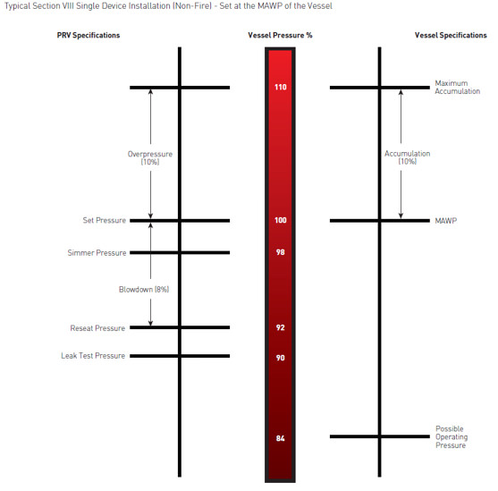
The lowest rating (MAWP or maximum allowable working pressure) should always be used among all safety devices within a system, including boilers, pressure vessels, and equipment piping systems, to determine the safety valve set pressure.
Avoid isolating safety valves from the system, such as by installing intervening shut-off valves located between the steam component or system and the inlet.
Contact the valve supplier immediately for any safety valve with a broken wire seal, as this indicates that the valve is unsafe for use. Safety valves are sealed and certified in order to prevent tampering that can prevent proper function.
Avoid attaching vent discharge piping directly to a safety valve, which may place unnecessary weight and additional stress on the valve, altering the set pressure.
(a) Each power boiler, nuclear boiler, and high temperature water boiler shall have safety valves or pressure relieving devices constructed, stamped and installed in accordance with the applicable section of the Code, except:
(2) Upon written request by the employer, the Division may permit three-way two-port valves to be installed under two safety valves, each with the required relieving capacity, provided they are so installed that both safety valves cannot be closed off from the boiler at the same time and provided the three-way valve will permit at least full flow to the safety valve in service at all time.
(b) The user shall maintain all pressure relieving devices in good operating condition. Where the valves cannot be tested in service, the user shall maintain and make available to the inspector records showing the test dates and set pressure for such valves.
3. Change without regulatory effect inserting "(a)" immediately preceding the first paragraph and "(b)" immediately preceding the fourth paragraph, filed 1-24-91 pursuant to section 100, Title 1, California Code of Regulations (Register 91, No. 7).
Shipment: All products and/or services covered by the quotation are sold F.O.B. either our plant in Linden, NJ or the manufacturer"s plant for the parts and/or valves required, unless otherwise indicated. The risk of loss or damage in transit will be upon the purchaser. The products will be prepared for shipment in a manner prescribed by us or the manufacturer and shipped by any public carrier which we deem satisfactory, unless the purchaser provides other specific shipping instructions when placing orders. Any date provided by us for completion of work or for shipment is intended as an estimate only and is not to be deemed a term of the quotation. Shipping charges shall be pre-paid and billed at the time of shipment.
Warranties and Limitations: We warrant only that our products will conform to their description herein and that at the time of sale our products will be free from defects on workmanship and material. The name and reputation of Certified Valve Repair stands prudently behind every valve or piece of equipment we recondition. We are valve repair specialists, if at any time, in any way, a valve or piece of equipment that we have repaired fails to provide complete satisfaction, please bring the matter to our attention. Every repaired valve, pump, instrument, or equipment when used in accordance with the manufacturer and our recommendations is guaranteed to be free from defective workmanship and material. We will repair or replace without charge, F.O.B. our plant any repaired unit which our own examination proves to be defective within a period stated by our firm at the time of delivery. We assume no responsibility for incidental damage or expense. Authorization is required before returned articles will be accepted.

Years ago, it was not uncommon to read news about tragic boiler explosions, sometimes resulting in mass destruction. Today, boilers are equipped with important safety devises to help protect against these types of catastrophes. Let’s take a look at the most critical of these devices: the safety valve.
The safety valve is one of the most important safety devices in a steam system. Safety valves provide a measure of security for plant operators and equipment from over pressure conditions. The main function of a safety valve is to relieve pressure. It is located on the boiler steam drum, and will automatically open when the pressure of the inlet side of the valve increases past the preset pressure. All boilers are required by ASME code to have at least one safety valve, dependent upon the maximum flow capacity (MFC) of the boiler. The total capacity of the safety valve at the set point must exceed the steam control valve’s MFC if the steam valve were to fail to open. In most cases, two safety valves per boiler are required, and a third may be needed if they do not exceed the MFC.
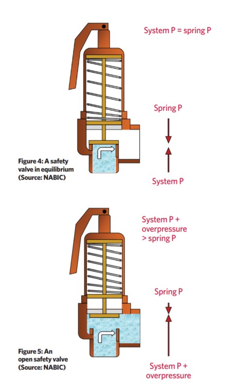
There are three main parts to the safety valve: nozzle, disc, and spring. Pressurized steam enters the valve through the nozzle and is then threaded to the boiler. The disc is the lid to the nozzle, which opens or closes depending on the pressure coming from the boiler. The spring is the pressure controller.
As a boiler starts to over pressure, the nozzle will start to receive a higher pressure coming from the inlet side of the valve, and will start to sound like it is simmering. When the pressure becomes higher than the predetermined pressure of the spring, the disc will start to lift and release the steam, creating a “pop” sound. After it has released and the steam and pressure drops below the set pressure of the valve, the spring will close the disc. Once the safety valve has popped, it is important to check the valve to make sure it is not damaged and is working properly.
A safety valve is usually referred to as the last line of safety defense. Without safety valves, the boiler can exceed it’s maximum allowable working pressure (MAWP) and not only damage equipment, but also injure or kill plant operators that are close by. Many variables can cause a safety valve on a boiler to lift, such as a compressed air or electrical power failure to control instrumentation, or an imbalance of feedwater rate caused by an inadvertently shut or open isolation valve.
Once a safety valve has lifted, it is important to do a complete boiler inspection and confirm that there are no other boiler servicing issues. A safety valve should only do its job once; safety valves should not lift continuously. Lastly, it is important to have the safety valves fully repaired, cleaned and recertified with a National Board valve repair (VR) stamp as required by local code or jurisdiction. Safety valves are a critical component in a steam system, and must be maintained.
All of Nationwide Boiler’s rental boilers include on to two safety valves depending on the size; one set at design pressure and the other set slightly higher than design. By request, we can reset the safeties to a lower pressure if the application requires it. In addition, the valves are thoroughly checked after every rental and before going out to a new customer, and they are replaced and re-certified as needed.
Tired of keeping track of your valve inventory’s annual certification records? We offer complete management of your safety relief valves. With an inventory of repair parts and in stock relief valves of all sizes, we can respond to any customer emergency. We offer annual certification services as well as repair of all major brands, including Kunkle, Conbraco, Consolidated, Dresser, Apollo and more.
In the latter half of the 19th century explosions of steam boilers were commonplace. As a consequence of this, a company was formed in Manchester with the objective of reducing the number of explosions by subjecting steam boilers to independent examination. This company was, in fact, the beginning of today’s Safety Federation (SAFed), the body whose approval is required for boiler controls and fittings in the UK.
After a comparatively short period, only eight out of the 11 000 boilers examined exploded. This compared to 260 steam boiler explosions in boilers not examined by the scheme. This success led to the Boiler Explosions Act (1882) which included a requirement for a boiler name-plate. An example of a boiler name-plate is shown in Figure 3.7.1.
The serial number and model number uniquely identify the boiler and are used when ordering spares from the manufacturer and in the main boiler log book.
In Europe, matters relating to the suitability of safety valves for steam boilers are governed by the European standard EN 12953. In the US and some other parts of the world, such matters are covered by ASME standards.
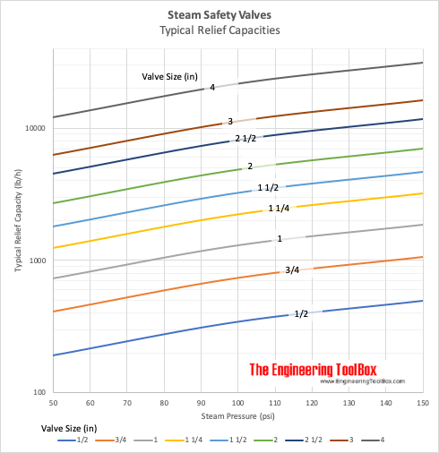
The total discharge capacity of the safety valve(s) must be at least equal to the ‘from and at 100°C’ capacity of the boiler. If the ‘from and at’ evaporation is used to size the safety valve, the safety valve capacity will always be higher than the actual maximum evaporative boiler capacity.
The discharge pipework from the safety valve must be unobstructed and drained at the base to prevent the accumulation of condensate. It is good practice to ensure that the discharge pipework is kept as short as possible with the minimum number of bends, so that the allowable backpressure indicated by the valve manufacturer is not exceeded.
It will be quite normal for the internal diameter of the discharge pipework to be more than the internal diameter of the safety valve outlet connection, but under no circumstances should it be less.
A steam boiler must be fitted with a stop valve (also known as a crown valve) which isolates the steam boiler and its pressure from the process or plant. It is generally an angle pattern globe valve of the screw-down variety. Figure 3.7.3 shows a typical stop valve of this type.
In the past, these valves have often been manufactured from cast iron, with steel and bronze being used for higher pressure applications. In the UK, BS 2790 (eventually to be replaced with EN 12953) states that cast iron valves are no longer permitted for this application on steam boilers. Nodular or spheroidal graphite (SG) iron should not be confused with grey cast iron as it has mechanical properties approaching those of steel. For this reason many boilermakers use SG iron valves as standard.
The stop valve is not designed as a throttling valve, and should be fully open or closed. It should always be opened slowly to prevent any sudden rise in downstream pressure and associated waterhammer, and to help restrict the fall in boiler pressure and any possible associated priming.
To comply with UK regulations, the valve should be of the ‘rising handwheel’ type. This allows the boiler operator to easily see the valve position, even from floor level. The valve shown is fitted with an indicator that makes this even easier for the operator.
On multi-boiler applications an additional isolating valve should be fitted, in series with the crown valve. At least one of these valves should be lockable in the closed position. The additional valve is generally a globe valve of the screw-down, non-return type which prevents one boiler pressurising another. Alternatively, it is possible to use a screw-down valve, with a disc check valve sandwiched between the flanges of the crown valve and itself.
The feedwater check valve (as shown in Figures 3.7.4 and 3.7.5) is installed in the boiler feedwater line between the feedpump and boiler. A boiler feed stop valve is fitted at the boiler shell.
The check valve includes a spring equivalent to the head of water in the elevated feedtank when there is no pressure in the boiler. This prevents the boiler being flooded by the static head from the boiler feedtank.
Under normal steaming conditions the check valve operates in a conventional manner to stop return flow from the boiler entering the feedline when the feedpump is not running. When the feedpump is running, its pressure overcomes the spring to feed the boiler as normal.
Because a good seal is required, and the temperatures involved are relatively low (usually less than 100°C) a check valve with a EPDM (Ethylene Propylene) soft seat is generally the best option.
The maintenance of water quality is essential to the safe and efficient operation of a steam boiler. The measurement and control of the various parameters is a complex topic, which is also covered by a number of regulations. It is therefore covered in detail later in this Block. The objective of the next few Sections is simply to identify the fittings to be seen on a boiler.
This controls the amount of Total Dissolved Solids (TDS) in the boiler water, and is sometimes also referred to as ‘continuous blowdown’. The boiler connection is typically DN15 or DN20. The system may be manual or automatic. Whatever system is used, the TDS in a sample of boiler water is compared with a set point; if the TDS level is too high, a quantity of boiler water is released to be replaced by feedwater with a much lower TDS level. This has the effect of diluting the water in the boiler, and reducing the TDS level.
This ejects the sludge or sediment from the bottom of the boiler. The control is a large (usually DN25 to DN50) key operated valve. This valve might normally be opened for a period of about 5 seconds, once per shift.
Figure 3.7.7 illustrates a key operated manual bottom blowdown valve whereas Figure 3.7.8 illustrates an automated bottom blowdown valve and its typical position in a blowdown system.
Pressure gauges are connected to the steam space of the boiler and usually have a ring type siphon tube which fills with condensed steam and protects the dial mechanism from high temperatures.
All steam boilers are fitted with at least one water level indicator, but those with a rating of 100 kW or more should be fitted with two indicators. The indicators are usually referred to as gauge glasses complying with EN 12953.
A gauge glass shows the current level of water in the boiler, regardless of the boiler’s operating conditions. Gauge glasses should be installed so that their lowest reading will show the water level at 50 mm above the point where overheating will occur. They should also be fitted with a protector around them, but this should not hinder visibility of the water level. Figure 3.7.10 shows a typical gauge glass.
Gauge glasses are prone to damage from a number of sources, such as corrosion from the chemicals in boiler water, and erosion during blowdown, particularly at the steam end. Any sign of corrosion or erosion indicates that a new glass is required.
If the water passages are choked an artificially high water level may be observed due to steam condensing in the glass. After testing, the glass will tend to remain empty unless the water level in the boiler is higher than the top connection, in which case water might flow into the glass from this connection.
Gauge glass levels must be treated with the utmost respect, as they are the only visual indicator of water level conditions inside the boiler. Any water level perceived as abnormal must be investigated as soon as it is observed, with immediate action taken to shut down the boiler burner if necessary.
The maintenance of the correct water level in a steam boiler is essential to its safe and efficient operation. The methods of sensing the water level, and the subsequent control of water level is a complex topic that is covered by a number of regulations. The following few Sections will provide a brief overview, and the topic will be discussed in much greater detail later.
The function of the level controls or alarms is checked daily using the sequencing purge valves. With the handwheel turned fully anticlockwise the valve is in the ‘normal working’ position and a back seating shuts off the drain connection. The handwheel dial may look similar to that shown in Figure 3.7.12. Some handwheels have no dial, but rely on a mechanism for correct operation.
Slowly move the handwheel further clockwise to full travel. The water connection is shut-off, the drain valve remains open, and the float chamber and steam connections are blown through. The boiler controls should operate as for lowered water level in boiler i.e. pump running and / or audible alarm sounding and burner cut-out. Alternatively if the level control chamber is fitted with a second or extra low water alarm, the boiler should lock-out.
Sequencing purge valves are provided by a number of different manufacturers. Each may differ in operating procedure. It is essential that the manufacturer’s instructions be followed regarding this operation.
Level control systems with sensors (or probes) which fit inside the boiler shell (or steam drum) are also available. These provide a higher degree of safety than those fitted externally. The level alarm systems may also provide a self-checking function on system integrity.
When a boiler is started from cold, the steam space is full of air. This air has no heat value, and will adversely affect steam plant performance due to its effect of blanketing heat exchange surfaces. The air can also give rise to corrosion in the condensate system, if not removed adequately.
The air may be purged from the steam space using a simple cock; normally this would be left open until a pressure of about 0.5 bar is showing on the pressure gauge. An alternative to the cock is a balanced pressure air vent which not only relieves the boiler operator of the task of manually purging air (and hence ensures that it is actually done), it is also much more accurate and will vent gases which may accumulate in the boiler. Typical air vents are shown in Figure 3.7.14.
When a boiler is taken off-line, the steam in the steam space condenses and leaves a vacuum. This vacuum causes pressure to be exerted on the boiler from the outside, and can result in boiler inspection doors leaking, damage to the boiler flat plates and the danger of overfilling a shutdown boiler. To avoid this, a vacuum breaker (see Figure 3.7.14) is required on the boiler shell.


 8613371530291