
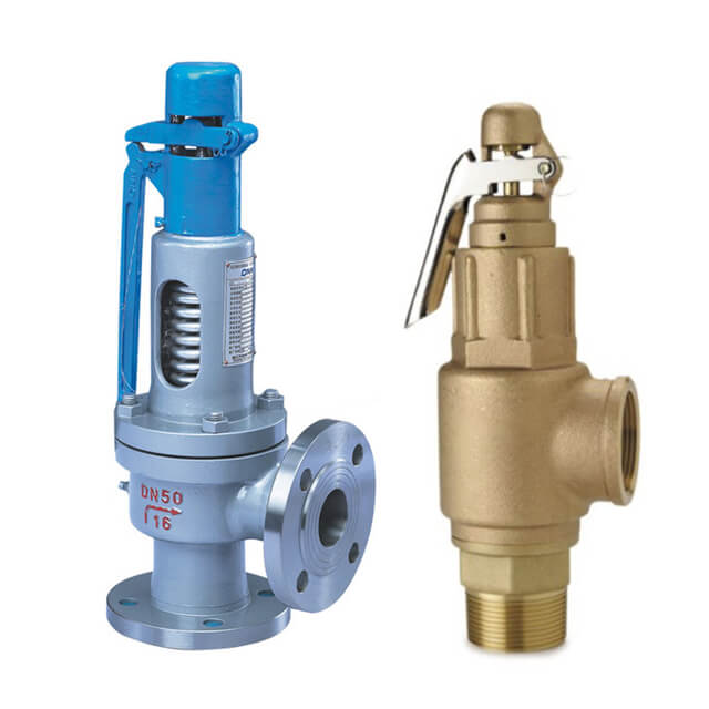
boiler safety valve sizing made in china
Safety valves are an arrangement or mechanism to release a substance from the concerned system in the event of pressure or temperature exceeding a particular preset limit. The systems in the context may be boilers, steam boilers, pressure vessels or other related systems. As per the mechanical arrangement, this one get fitted into the bigger picture (part of the bigger arrangement) called as PSV or PRV that is pressure safety or pressure relief valves.
This type of safety mechanism was largely implemented to counter the problem of accidental explosion of steam boilers. Initiated in the working of a steam digester, there were many methodologies that were then accommodated during the phase of the industrial revolution. And since then this safety mechanism has come a long way and now accommodates various other aspects.
These aspects like applications, performance criteria, ranges, nation based standards (countries like United States, European Union, Japan, South Korea provide different standards) etc. manage to differentiate or categorize this safety valve segment. So, there can be many different ways in which these safety valves get differentiated but a common range of bifurcation is as follows:
The American Society of Mechanical Engineers (ASME) I tap is a type of safety valve which opens with respect to 3% and 4% of pressure (ASME code for pressure vessel applications) while ASME VIII valve opens at 10% over pressure and closes at 7%. Lift safety valves get further classified as low-lift and full lift. The flow control valves regulate the pressure or flow of a fluid whereas a balanced valve is used to minimize the effects induced by pressure on operating characteristics of the valve in context.
A power operated valve is a type of pressure relief valve is which an external power source is also used to relieve the pressure. A proportional-relief valve gets opened in a relatively stable manner as compared to increasing pressure. There are 2 types of direct-loaded safety valves, first being diaphragms and second: bellows. diaphragms are valves which spring for the protection of effects of the liquid membrane while bellows provide an arrangement where the parts of rotating elements and sources get protected from the effects of the liquid via bellows.
In a master valve, the operation and even the initiation is controlled by the fluid which gets discharged via a pilot valve. Now coming to the bigger picture, the pressure safety valves based segment gets classified as follows:
So all in all, pressure safety valves, pressure relief valves, relief valves, pilot-operated relief valves, low pressure safety valves, vacuum pressure safety valves etc. complete the range of safety measures in boilers and related devices.
Safety valves have different discharge capacities. These capacities are based on the geometrical area of the body seat upstream and downstream of the valve. Flow diameter is the minimum geometrical diameter upstream and downstream of the body seat.
The nominal size designation refers to the inlet orifice diameter. A safety Valve"s theoretical flowing capacity is the mass flow through an orifice with the same cross-sectional area as the valve"s flow area. This capacity does not account for the flow losses caused by the valve. The actual capacity is measured, and the certified flow capacity is the actual flow capacity reduced by 10%.
A safety valve"s discharge capacity is dependent on the set pressure and position in a system. Once the set pressure is calculated, the discharge capacity must be determined. Safety valves may be oversized or undersized depending on the flow throughput and/or the valve"s set pressure.
The actual discharge capacity of a safety valve depends on the type of discharge system used. In liquid service, safety valves are generally automatic and direct-pressure actuated.
A safety valve is used to protect against overpressure in a fluid system. Its design allows for a lift in the disc, indicating that the valve is about to open. When the inlet pressure rises above the set pressure, the guide moves to the open position, and media flows to the outlet via the pilot tube. Once the inlet pressure falls below the set pressure, the main valve closes and prevents overpressure. There are five criteria for selecting a safety valve.
The first and most basic requirement of a safety valve is its ability to safely control the flow of gas. Hence, the valve must be able to control the flow of gas and water. The valve should be able to withstand the high pressures of the system. This is because the gas or steam coming from the boiler will be condensed and fill the pipe. The steam will then wet the safety valve seat.
The other major requirement for safety valves is their ability to prevent pressure buildup. They prevent overpressure conditions by allowing liquid or gas to escape. Safety valves are used in many different applications. Gas and steam lines, for example, can prevent catastrophic damage to the plant. They are also known as safety relief valves. During an emergency, a safety valve will open automatically and discharge gas or liquid pressure from a pressurized system, preventing it from reaching dangerous levels.
The discharge capacity of a safety valve is based on its orifice area, set pressure, and position in the system. A safety valve"s discharge capacity should be calculated based on the maximum flow through its inlet and outlet orifice areas. Its nominal size is often determined by manufacturer specifications.
Its discharge capacity is the maximum flow through the valve that it can relieve, based on the maximum flow through each individual flow path or combined flow path. The discharge pressure of the safety valve should be more than the operating pressure of the system. As a thumb rule, the relief pressure should be 10% above the working pressure of the system.
It is important to choose the discharge capacity of a safety valve based on the inlet and output piping sizes. Ideally, the discharge capacity should be equal to or greater than the maximum output of the system. A safety valve should also be installed vertically and into a clean fitting. While installing a valve, it is important to use a proper wrench for installation. The discharge piping should slope downward to drain any condensate.
The discharge capacity of a safety valve is measured in a few different ways. The first is the test pressure. This gauge pressure is the pressure at which the valve opens, while the second is the pressure at which it re-closes. Both are measured in a test stand under controlled conditions. A safety valve with a test pressure of 10,000 psi is rated at 10,000 psi (as per ASME PTC25.3).
The discharge capacity of a safety valve should be large enough to dissipate a large volume of pressure. A small valve may be adequate for a smaller system, but a larger one could cause an explosion. In a large-scale manufacturing plant, safety valves are critical for the safety of personnel and equipment. Choosing the right valve size for a particular system is essential to its efficiency.
Before you use a safety valve, you need to know its discharge capacity. Here are some steps you need to follow to calculate the discharge capacity of a safety valve.
To check the discharge capacity of a safety valve, the safety valve should be installed in the appropriate location. Its inlet and outlet pipework should be thoroughly cleaned before installation. It is important to avoid excessive use of PTFE tape and to ensure that the installation is solid. The safety valve should not be exposed to vibration or undue stress. When mounting a safety valve, it should be installed vertically and with the test lever at the top. The inlet connection of the safety valve should be attached to the vessel or pipeline with the shortest length of pipe. It must not be interrupted by any isolation valve. The pressure loss at the inlet of a safety valve should not exceed 3% of the set pressure.
The sizing of a safety valve depends on the amount of fluid it is required to control. The rated discharge capacity is a function of the safety valve"s orifice area, set pressure, and position in the system. Using the manufacturer"s specifications for orifice area and nominal size of the valve, the capacity of a safety valve can be determined. The discharge flow can be calculated using the maximum flow through the valve or the combined flows of several paths. When sizing a safety valve, it"s necessary to consider both its theoretical and actual discharge capacity. Ideally, the discharge capacity will be equal to the minimum area.
To determine the correct set pressure for a safety valve, consider the following criteria. It must be less than the MAAP of the system. Set pressure of 5% greater than the MAAP will result in an overpressure of 10%. If the set pressure is higher than the MAAP, the safety valve will not close. The MAAP must never exceed the set pressure. A set pressure that is too high will result in a poor shutoff after discharge. Depending on the type of valve, a backpressure variation of 10% to 15% of the set pressure cannot be handled by a conventional valve.

Fired pressure vessels shall be fitted with safety relieving devices with sufficient capacity to relieve all vapor that may be generated in the vessels during normal operation. The safety relieving devices shall be fitted with proper controls to ensure safe operation.
To eliminate the necessity of shutting the system down for the inspection, a three-way stop valve may be installed under 2 safety valves, each with the required relieving capacity, installed so that both safety valves cannot be closed off from the vaporizer at the same time. Alternatively may 2 or more separate safety valves be installed with individual shutoff valves, in which case the shutoff valve stems is mechanically interconnected in a manner that allow full required flow capacity at all times.

The main purpose of a safety valve is to prevent the pressure in a system to exceed the certification pressure. Above certification pressure, no one can guaranty the systems safety - and especially for a steam system with very hot gas with huge amount of latent heat, the consequences can be dramatically.
The size of the safety valve depends primarily on the maximum boiler output and the operation pressure of the system. The safety valve shall as minimum have the evacuation capacity of all the vapor the boiler can produce running at full power at working (or certification) pressure.
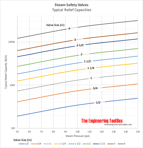
The table below can be used to select a typical safety valve based on boiler output. Before final design, always consult the manufactures documentation.
Note! The table above is based on low pressure steam of 100 kN/m2 (1 bar)or 15 psiin imperial units. Latent heat of saturated steam is 2201 kJ/kg (945 Btu/lb). 1 N/m2 = 1 Pa = 1.4504 x 10⁻⁴ lb/in2 (psi) = 10-5 bar For higher pressure, steam is compressed and require less volume - required size of the valve reduced

There are various safety valves available to meet various applications and performance criteria demanded by various industries. Furthermore, national standards determine many types of varied safety valves.
Standard ASME I and ASME VIII standards for boiler applications and vessels and ASME / ANSI PTC 25.3 standards for safety valves and relief valves provide the following definition. These standards set performance characteristics and define various types of safety valves used:
ASME I valve - A safety relief valve conforming to the requirements of Section I of the ASME pressure vessel code for boiler applications which will open within 3% overpressure and close within 4%. It will usually feature two blowdown rings and is identified by a National Board ‘V’ stamp.
ASME VIII valve - A safety relief valve conforming to the requirements of Section VIII of the ASME pressure vessel code for pressure vessel applications which will open within 10% overpressure and close within 7%. Identified by a National Board ‘UV’ stamp.
Full bore safety valve - A safety valve having no protrusions in the bore, and wherein the valve lifts to an extent sufficient for the minimum area at any section, at or below the seat, to become the controlling orifice.
Conventional safety relief valve - The spring housing is vented to the discharge side, hence operational characteristics are directly affected by changes in the backpressure to the valve.
Balanced safety relief valve - A balanced valve incorporates a means of minimizing the effect of backpressure on the operational characteristics of the valve.
Pilot operated pressure relief valve - The major relieving device is combined with, and is controlled by, a self-actuated auxiliary pressure relief device.
Power-actuated safety relief valve - A pressure relief valve in which the major pressure-relieving device is combined with, and controlled by, a device requiring an external source of energy.
Standard safety valve - A valve which, following the opening, reaches the degree of lift necessary for the mass flowrate to be discharged within a pressure rise of not more than 10%. (The valve is characterized by a pop-type action and is sometimes known as high lift).
Full lift (Vollhub) safety valve - A safety valve which, after commencement of lift, opens rapidly within a 5% pressure rise up to the full lift as limited by the design. The amount of lift up to the rapid opening (proportional range) shall not be more than 20%.
Directly loaded safety valve - A safety valve in which the opening force underneath the valve disc is opposed by a closing force such as a spring or a weight.
Proportional safety valve - A safety valve that opens more or less steadily in relation to the increase in pressure. Sudden opening within a 10% lift range will not occur without a pressure increase. Following opening within a pressure of not more than 10%, these safety valves achieve the lift necessary for the mass flow to be discharged.
Diaphragm safety valve - A directly loaded safety valve wherein linear moving and rotating elements and springs are protected against the effects of the fluid by a diaphragm
Bellows safety valve - A directly loaded safety valve wherein sliding and (partially or fully) rotating elements and springs are protected against the effects of the fluids by a bellows. The bellows may be of such a design that it compensates for influences of backpressure.
Controlled safety valve- Consists of the main valve and a control device. It also includes direct acting safety valves with supplementary loading in which, until the set pressure is reached, an additional force increases the closing force.
Safety valve - A safety valve which automatically, without the assistance of any energy other than that of the fluid concerned, discharges a quantity of the fluid so as to prevent a predetermined safe pressure from being exceeded, and which is designed to re-close and prevent further flow of fluid after normal pressure conditions of service have been restored. Note; the valve can be characterized either by pop action (rapid opening) or by opening in proportion (not necessarily linear) to the increase in pressure over the set pressure.
Directly loaded safety valve - A safety valve in which the loading due to the fluid pressure underneath the valve disc is opposed only by a direct mechanical loading device such as weight, lever, and weight, or a spring.
Assisted safety valve - A safety valve which by means of a powered assistance mechanism, may additionally be lifted at a pressure lower than the set pressure and will, even in the event of a failure of the assistance mechanism, comply with all the requirements for safety valves given in the standard.
Supplementary loaded safety valve - A safety valve that has, until the pressure at the inlet to the safety valve reaches the set pressure, an additional force, which increases the sealing force.
Notes; This additional strength (additional burden), which can be provided through foreign resources, is reliably released when the pressure on the safety valve inlet reaches the specified pressure. The amount of additional loading is very regulated that if the additional loading is not released, the safety valve will reach its certified discharge capacity at a pressure which is no greater than 1.1 times the maximum pressure that is permitted to be protected.
Pilot operated safety valve - A safety valve, the operation of which is initiated and controlled by the fluid discharged from a pilot valve, which is itself, a directly loaded safety valve subject to the requirement of the standard.
The common characteristic shared between the definitions of conventional safety valves in the different standards, is that their operational characteristics are affected by any backpressure in the discharge system. It is important to note that the total backpressure is generated from two components; superimposed backpressure and the built-up backpressure:
Subsequently, in a conventional safety valve, only the superimposed backpressure will affect the opening characteristic and set value, but the combined backpressure will alter the blowdown characteristic and re-seat value.
Once the valve starts to open, the effects of built-up backpressure also have to be taken into account. For a conventional safety valve with the spring housing vented to the discharge side of the valve.
Therefore, if the back pressure is greater than the overpressure, the valve will tend to close, reducing the flow. This can lead to instability within the system and can result in flutter or chatter of the valve.
In general, if conventional safety valves are used in applications, where there is excessive built-up backpressure, they will not perform as expected. According to the API 520 Recommended Practice Guidelines:
A conventional pressure relief valve should typically not be used when the built-up backpressure is greater than 10% of the set pressure at 10% overpressure. A higher maximum allowable built-up backpressure may be used for overpressure greater than 10%.
The European Standard EN ISO 4126, however, states that the built-up backpressure should be limited to 10% of the set pressure when the valve is discharging at the certified capacity.
For the majority of steam applications, the back pressure can be maintained within these limits by carefully sizing any discharge pipes. This will be discussed in Module 9.4. If, however, it is not feasible to reduce the backpressure, then it may be necessary to use a balanced safety valve.
Balanced safety valves are those that incorporate a means of eliminating the effects of backpressure. There are two basic designs that can be used to achieve this:
The bellows arrangement prevents back pressure acting on the upper side of the disc within the area of the bellows. The disc area extending beyond the bellows and the opposing disc area are equal, and so the forces acting on the disc are balanced, and the backpressure has little effect on the valve opening pressure.
Bellows failure is an important concern when using a bellows balanced safety valve, as this may affect the set pressure and capacity of the valve. It is important, therefore, that there is some mechanism for detecting any uncharacteristic fluid flow through the bellows vents. In addition, some bellows balanced safety valves include an auxiliary piston that is used to overcome the effects of backpressure in the case of bellows failure. This type of safety valve is usually only used on critical applications in the oil and petrochemical industries.
Since balanced pressure relief valves are typically more expensive than their unbalanced counterparts, they are commonly only used where high-pressure manifolds are unavoidable, or in critical applications where a very precise set pressure or blowdown is required.
This type of safety valve uses the flowing medium itself, through a pilot valve, to apply the closing force on the safety valve disc. The pilot valve is itself a small safety valve.
The diaphragm type is typically only available for low-pressure applications and it produces a proportional type action, characteristic of relief valves used in liquid systems. They are therefore of little use in steam systems, consequently, they will not be considered in this text.
The piston-type valve consists of the main valve, which uses a piston-shaped closing device (or obturator), and an external pilot valve. Below photo shows a diagram of a typical piston type, pilot-operated safety valve.
The piston and seating arrangement incorporated in the main valve is designed so that the bottom area of the piston, exposed to the inlet fluid, is less than the area of the top of the piston. As both ends of the piston are exposed to the fluid at the same pressure, this means that under normal system operating conditions, the closing force, resulting from the larger top area, is greater than the inlet force. The resultant downward force therefore holds the piston firmly on its seat.
If the inlet pressure were to rise, the net closing force on the piston also increases, ensuring that a tight shut-off is continually maintained. However, when the inlet pressure reaches the set pressure, the pilot valve will pop open to release the fluid pressure above the piston. With much less fluid pressure acting on the upper surface of the piston, the inlet pressure generates a net upwards force and the piston will leave its seat. This causes the main valve to pop open, allowing the process fluid to be discharged.
When the inlet pressure has been sufficiently reduced, the pilot valve will reclose, preventing the further release of fluid from the top of the piston, thereby re-establishing the net downward force, and causing the piston to reseat.
Pilot operated safety valves offer good overpressure and blowdown performance (a blowdown of 2% is attainable). For this reason, they are used where a narrow margin is required between the set pressure and the system operating pressure. Pilot operated valves are also available in much larger sizes, making them the preferred type of safety valve for larger capacities.
One of the main concerns with pilot operated safety valves is that the small bore, pilot connecting pipes are susceptible to blockage by foreign matter, or due to the collection of condensate in these pipes. This can lead to the failure of the valve, either in the open or closed position, depending on where the blockage occurs.
The terms full lift, high lift and low lift refer to the amount of travel the disc undergoes as it moves from its closed position to the position required to produce the certified discharge capacity, and how this affects the discharge capacity of the valve.
A full lift safety valve is one in which the disc lifts sufficiently, so that the curtain area no longer influences the discharge area. The discharge area, and therefore the capacity of the valve are subsequently determined by the bore area. This occurs when the disc lifts a distance of at least a quarter of the bore diameter. A full lift conventional safety valve is often the best choice for general steam applications.
The disc of a high lift safety valve lifts a distance of at least 1/12th of the bore diameter. This means that the curtain area, and ultimately the position of the disc, determines the discharge area. The discharge capacities of high lift valves tend to be significantly lower than those of full lift valves, and for a given discharge capacity, it is usually possible to select a full lift valve that has a nominal size several times smaller than a corresponding high lift valve, which usually incurs cost advantages.Furthermore, high lift valves tend to be used on compressible fluids where their action is more proportional.
In low lift valves, the disc only lifts a distance of 1/24th of the bore diameter. The discharge area is determined entirely by the position of the disc, and since the disc only lifts a small amount, the capacities tend to be much lower than those of full or high lift valves.
Except when safety valves are discharging, the only parts that are wetted by the process fluid are the inlet tract (nozzle) and the disc. Since safety valves operate infrequently under normal conditions, all other components can be manufactured from standard materials for most applications. There are however several exceptions, in which case, special materials have to be used, these include:
Cast steel - Commonly used on higher pressure valves (up to 40 bar g). Process type valves are usually made from a cast steel body with an austenitic full nozzle type construction.
For all safety valves, it is important that moving parts, particularly the spindle and guides are made from materials that will not easily degrade or corrode. As seats and discs are constantly in contact with the process fluid, they must be able to resist the effects of erosion and corrosion.
The spring is a critical element of the safety valve and must provide reliable performance within the required parameters. Standard safety valves will typically use carbon steel for moderate temperatures. Tungsten steel is used for higher temperature, non-corrosive applications, and stainless steel is used for corrosive or clean steam duty. For sour gas and high temperature applications, often special materials such as monel, hastelloy and ‘inconel’ are used.
Standard safety valves are generally fitted with an easing lever, which enables the valve to be lifted manually in order to ensure that it is operational at pressures in excess of 75% of set pressure. This is usually done as part of routine safety checks, or during maintenance to prevent seizing. The fitting of a lever is usually a requirement of national standards and insurance companies for steam and hot water applications. For example, the ASME Boiler and Pressure Vessel Code states that pressure relief valves must be fitted with a lever if they are to be used on air, water over 60°C, and steam.
A test gag (Figure 9.2.7) may be used to prevent the valve from opening at the set pressure during hydraulic testing when commissioning a system. Once tested, the gag screw is removed and replaced with a short blanking plug before the valve is placed in service.
The amount of fluid depends on the particular design of the safety valve. If the emission of this fluid into the atmosphere is acceptable, the spring housing may be vented to the atmosphere – an open bonnet. This is usually advantageous when the safety valve is used on high-temperature fluids or for boiler applications as, otherwise, high temperatures can relax the spring, altering the set pressure of the valve. However, using an open bonnet exposes the valve spring and internals to environmental conditions, which can lead to damage and corrosion of the spring.
When the fluid must be completely contained by the safety valve (and the discharge system), it is necessary to use a closed bonnet, which is not vented to the atmosphere. This type of spring enclosure is almost universally used for small screwed valves and, it is becoming increasingly common on many valve ranges since, particularly on steam, discharge of the fluid could be hazardous to personnel.
Some safety valves, most commonly those used for water applications, incorporate a flexible diaphragm or bellows to isolate the safety valve spring and upper chamber from the process fluid, (see Figure 9.2.9).
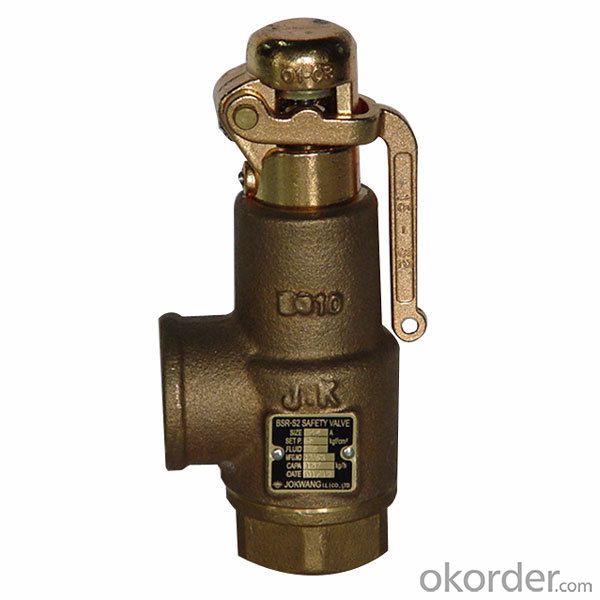
Spring Loaded Safety Relief Valve is used in power plant boilers, pressure containers and temperature reducing devices and other facilities. It serves to prevent pressure from exceeding max. allowed value and ensure the safety of the device during working. Steam Safety Valve sizing and selection acc. to API 520 (ASME sec Ⅷ), designed acc. to API 526, test acc. to API 527 (ASME PTC 25), flange acc. to ASME B16.5. This valve"s type include A48C Open Bonnet Plain Lever Safety Valve, A48Y High Temperature and High Pressure With Radiator Safety Valve, High Performance Steam Safety Valve which meets the requirement of ASME secⅠ, High Temperature High Pressure Welded Safety Valve.

As soon as mankind was able to boil water to create steam, the necessity of the safety device became evident. As long as 2000 years ago, the Chinese were using cauldrons with hinged lids to allow (relatively) safer production of steam. At the beginning of the 14th century, chemists used conical plugs and later, compressed springs to act as safety devices on pressurised vessels.
Early in the 19th century, boiler explosions on ships and locomotives frequently resulted from faulty safety devices, which led to the development of the first safety relief valves.
In 1848, Charles Retchie invented the accumulation chamber, which increases the compression surface within the safety valve allowing it to open rapidly within a narrow overpressure margin.
Today, most steam users are compelled by local health and safety regulations to ensure that their plant and processes incorporate safety devices and precautions, which ensure that dangerous conditions are prevented.
The principle type of device used to prevent overpressure in plant is the safety or safety relief valve. The safety valve operates by releasing a volume of fluid from within the plant when a predetermined maximum pressure is reached, thereby reducing the excess pressure in a safe manner. As the safety valve may be the only remaining device to prevent catastrophic failure under overpressure conditions, it is important that any such device is capable of operating at all times and under all possible conditions.
Safety valves should be installed wherever the maximum allowable working pressure (MAWP) of a system or pressure-containing vessel is likely to be exceeded. In steam systems, safety valves are typically used for boiler overpressure protection and other applications such as downstream of pressure reducing controls. Although their primary role is for safety, safety valves are also used in process operations to prevent product damage due to excess pressure. Pressure excess can be generated in a number of different situations, including:
The terms ‘safety valve’ and ‘safety relief valve’ are generic terms to describe many varieties of pressure relief devices that are designed to prevent excessive internal fluid pressure build-up. A wide range of different valves is available for many different applications and performance criteria.
In most national standards, specific definitions are given for the terms associated with safety and safety relief valves. There are several notable differences between the terminology used in the USA and Europe. One of the most important differences is that a valve referred to as a ‘safety valve’ in Europe is referred to as a ‘safety relief valve’ or ‘pressure relief valve’ in the USA. In addition, the term ‘safety valve’ in the USA generally refers specifically to the full-lift type of safety valve used in Europe.
Pressure relief valve- A spring-loaded pressure relief valve which is designed to open to relieve excess pressure and to reclose and prevent the further flow of fluid after normal conditions have been restored. It is characterised by a rapid-opening ‘pop’ action or by opening in a manner generally proportional to the increase in pressure over the opening pressure. It may be used for either compressible or incompressible fluids, depending on design, adjustment, or application.
Safety valves are primarily used with compressible gases and in particular for steam and air services. However, they can also be used for process type applications where they may be needed to protect the plant or to prevent spoilage of the product being processed.
Relief valve - A pressure relief device actuated by inlet static pressure having a gradual lift generally proportional to the increase in pressure over opening pressure.
Relief valves are commonly used in liquid systems, especially for lower capacities and thermal expansion duty. They can also be used on pumped systems as pressure overspill devices.
Safety relief valve - A pressure relief valve characterised by rapid opening or pop action, or by opening in proportion to the increase in pressure over the opening pressure, depending on the application, and which may be used either for liquid or compressible fluid.
In general, the safety relief valve will perform as a safety valve when used in a compressible gas system, but it will open in proportion to the overpressure when used in liquid systems, as would a relief valve.
Safety valve- A valve which automatically, without the assistance of any energy other than that of the fluid concerned, discharges a quantity of the fluid so as to prevent a predetermined safe pressure being exceeded, and which is designed to re-close and prevent further flow of fluid after normal pressure conditions of service have been restored.
Kunkle Relief Valve OverviewWhen it comes to industrial and commercial safety and relief valve products, Kunkle’s valve’s catalog is second to none in steam, air, gas, and liquid applications.
Kunkle relief valves range in size from ¼” NPT to 6” flange and are suitable in cryogenic and high temperatures up to 800°F environments at vacuum to 7,500 psig pressure. Kunkle Valve’s code certifications meet several global and national board standards, including ASME Section I, Section IV, and Section VIII, PED, CRN, TU and Chinese, as well as non-code requirements.
Relief Valves for Steam ServiceSteam supplies heat for industrial and chemical processes and also is used to heat buildings, supply mechanical energy, and drive mechanical equipment. Steam moves from the boiler to the end point, then heats by direct heating or indirect heating through a heat exchanger. Kunkle steam relief valves are critical to protecting equipment such as boilers, steam lines, and pressure valves, from being over-pressurized.
Relief Valves for Air ServiceKunkle designs valves for air service, for example for air compressors in mechanical shops and small factories where either low-pressure or high-pressure air is required. NASVI stocks Kunkle relief valves for air service in iron, steel and bronze for a variety of uses.
Relief Valves for Liquid ServiceKunkle also makes valves for liquid service, which provide bypass relief in a variety of applications and liquid types.
More About KunkleKunkle Valve is a renowned pressure relief valve manufacturer. Erastus B. Kunkle invented the safety valve to prevent overpressure in locomotive engines. Kunkle patented it in 1875. Since that time, Kunkle has earned its reputation for high-quality valves, and other equipment manufacturers ship their products with Kunkle’s valves pre-installed.
NASVI has stocked Kunkle safety relief valves since we opened in 1975, so we are confident when we call ourselves Kunkle safety valve experts. Every day we fulfill orders for our customers looking for Kunkle relief valves for steam, air, gas, and liquid applications.

Safety valves or pressure relief valves are pressure regulating devices that are responsible for expelling excess pressure from the system when the maximum pressure levels for which they have been designed are exceeded, usually due to a
Safety valves perform their function when the pressure of the system where the fluid is contained, becomes higher than the maximum set pressure of the valve previously adjusted. When the system pressure is higher than the valve’s set
pressure, this opens, releasing the excess pressure to the atmosphere or to containment tanks, depending on the toxicity of the fluid. After releasing the excess, the valve closes again and the system pressure returns to normal.
To ensure total safety of personnel and installation, make sure that the valves have passed all safety tests and meet the requirements of the system where they are to be installed. All our valves are supplied with certificates of materials, cas-
What is the difference between the instantaneous full opening safety valve AIT (PSV) and the normal opening relief valve AN or progressive opening relief valve AP (PRV)?
The Pressure Safety Valve (PSV) opens instantaneously and fully upon reaching the set pressure for which it is designed, expelling the excess pressure from the system immediately. They are optimised for use with steam or gases.
In contrast, the normally or progressively opening Pressure Relief Valve (PRV) opens gradually as the system pressure rises above the set pressure of the valve above its setting. They are optimised to work with liquids.
At VYC Industrial we are specialists in the design and manufacture of all types of safety valves. We have a wide range of safety valves to cover all the needs of the sector.
The Mod. 496 EN safety valve works as an automatic pressure releasing regulator activated by the static pressure existing at the entrance to the valve and is characterized by its ability to open instantly and totally.
The Mod. 495 EN pressure relief valve works as an automatic pressure releasing regulator activated by the static pressure existing at the entrance to the valve and is characterized by its ability to open instantly and totally.
The relief valve works as an automatic pressure releasing regulator activated by the static pressure existing at the entrance to the valve and is characterized by its ability to open instantly and totally.
The valve works as an automatic pressure releasing regulator activated by the static pressure existing at the entrance to the valve and is characterized by its ability to open instantly and totally.
The valve works as an automatic pressure releasing regulator activated by the static pressure existing at the entrance to the valve and is characterized by its ability to open instantly and totally.
The valve works as an automatic pressure releasing regulator activated by the static pressure existing at the entrance to the valve and is characterized by its ability to open instantly and totally.
The valve works as an automatic pressure releasing regulator activated by the static pressure existing at the entrance to the valve and is characterized by its ability to open instantly and totally.
The valve works as an automatic pressure releasing regulator activated by the static pressure existing at the entrance to the valve and is characterized by its ability to open instantly and totally.
The valve works as an automatic pressure releasing regulator activated by the static pressure existing at the entrance to the valve and is characterized by its ability to open, at the fi rst proportional to the pressure increase, and after instantly and totally.
The valve works as an automatic pressure releasing regulator activated by the static pressure existing at the entrance to the valve and is characterized by its ability to open, at the fi rst proportional to the pressure increase, and after instantly and totally.
The valve works as an automatic pressure releasing regulator activated by the static pressure existing at the entrance to the valve and is characterized by its ability to open, at the fi rst proportional to the pressure increase, and after instantly and totally.
The valve works as an automatic pressure releasing regulator activated by the static pressure existing at the entrance to the valve and is characterized by its ability to open proportional to the pressure increase.
The valve works as an automatic pressure releasing regulator activated by the static pressure existing at the entrance to the valve and is characterized by its ability to open proportional to the pressure increase.
The valve works as an automatic pressure releasing regulator activated by the static pressure existing at the entrance to the valve and is characterized by its ability to open instantly and totally.
The valve works as an automatic pressure releasing regulator activated by the static pressure existing at the entrance to the valve and is characterized by its ability to open instantly and totally.
The valve works as an automatic pressure releasing regulator activated by the static pressure existing at the entrance to the valve and is characterized by its ability to open instantly and totally.
The valve works as an automatic pressure releasing regulator activated by the static pressure existing at the entrance to the valve and is characterized by its ability to open instantly and totally.
The valve works as an automatic pressure releasing regulator activated by the static pressure existing at the entrance to the valve and is characterized by its ability to open instantly and totally.
They are used in places such as power, chemical and petrochemical plants to discharge safety valves, control valves, etc. in pressure lines and equipment that convey compressible substances such as steam, air, carbon dioxide, helium, methane, nitrogen, oxygen and other gases.
Test bench for regular inspections and setting and resetting safety valves. Ideal for distributors, maintenance companies or with in-house maintenance. It allows safety valves to be adjusted, tested and/or checked to the test pressure (setting) Pe wile cold (simulating service conditions), matching the opening pressure Ps and the closing pressure Pc, in accordance with the standard regulations.
Controlled safety pressure relief system CSPRS valves are mainly used where conventional direct-loaded spring action valves cannot guarantee the opening and closing margins that certain specifi c conditions of service demand.
The objective is to help the closure by means of pressure so that the valve remains completely watertight until reaching the set pressure and/or to activate the opening with pressure.
Increase the operating pressure of the system up to 99.9% of the set pressure.The control safety pressure relief system CSPRS device can be used with any safety valve available in the market and in particular, with models VYC Mod. 485, 486, 494, 495 and 496.
**Update to this article, June 7, 2022 : If you found this article helpful, here is a link to another article I recently found that does a nice job explaining the topic: ENGINEERS BEWARE: API vs ASME Relief Valve Orifice Size – Petro Chem Engineering (petrochemengg.com)
NOTE: this article is written to an audience that is familiar with PSVs, PSV sizing, and API and ASME standards at a basic level. I initially wrote this article in early 2017, and due to some great input and questions made significant revisions to increase clarity in mid-2018. I hope it is helpful to you, please send me a message with any comments/questions!
If you"ve ever sized/selected a Pressure Safety-Relief Valve (PSV) using vendor sizing programs or good-old hand calculations, you"ve probably run into a very strange anomaly: Why does a PSV orifice size change between American Petroleum Institute (API) and American Society of Mechanical Engineers (ASME) data sets? What is an "effective" orifice area? How do I know which standard to use when selecting a PSV?
Usually, this issue is one of curiosity and doesn"t affect the end result of what valve is chosen. Common practice is to default to API sizing equations and parameters, and only use ASME data sets for situations outside of the API letter-designations. But what if I told you that approach is likely causing you to oversize about 10% of your PSVs and their respective piping systems?
Too often, we leave that third part out of the process, and simply calculate relief loads and select valves using API techniques, without ever checking our selection against certified ASME data. Proper application of these standards is the first key point of this article:
Initial sizing and valve selection is done using API equations, and final valve selection and certification is done using ASME-certified coefficients and capacities.
When sizing a PSV, the sizing equations are always API 520. When a PSV is certified, it is always certified to ASME BPVC (whether one “selects” ASME certification or not!) It"s important to remember that the ASME BPVC is the "code", the standard to which we must design. API 520/526 are "recommended practices" which were developed to give engineers a tool to meet the ASME requirements. Another way to look at it: ASME BPVC sets the goal, API 520/526 provide the instructions, and ASME has the final say.
The BPVC is an enormous code, and not reviewed in detail here. On the subject of PSVs, it basically says that a PSV must be capable of relieving the required load, and it must be tested in a specific manner to be certified to do so. If a valve is tested per the specific directions in the BPVC, it will be ASME certified and receive an ASME UV stamp.
The first thing API does is attempt to standardize physical PSV sizes and design, and it does so in API RP 526, which is targeted at PSV manufacturers. API provides pre-defined valve sizes, with letter designations D through T (API 526). It also defines other details directed toward valve manufacturers (such as temperature ratings). All of this is intended as minimum design standards, and manufacturers are free to exceed these parameters as they wish.
The second thing API does is provide standardized equations and parameters to use when trying to figure out just what size of a PSV one needs for a particular scenario. The equations account for design parameters that ASME doesn"t speak to, such as specific fluid properties, backpressures, critical flow, two-phase flow, and many other aspects of fluid dynamics that will affect the ability of a particular valve to relieve a required load.
API sizing equations are by nature theoretical, standardized, and use default or "dummy" values for several sizing parameters that may or may not reflect the actual values for any specific valve.
API RP 520 very clearly talks about this, and emphasizes that the intended use of its equations is to determine a preliminary valve size, which should be verified with actual data. API intends PSV sizing to be a two-step process, but we are often unaware of this because we (gasp) don’t read the full standard, and/or rely solely on vendor sizing software that hides the iteration from us. See API 520, part 1, section 5.2 for further explanation.
When valves are built, they are built to the API RP 526 standard, however, as one might imagine, when valves are actually tested and certified, the results don’t match up identically to the theoretical values that were calculated. This is where API and ASME intersect; we switch from calculations (API) which were used as a basis to design the valve, to actual empirical data (ASME) to certify the valve. When a valve manufacturer gets the UV code stamp that certifies the valve orifice size and capacity, it is based on actual test results, not API sizing standards. And ASME (which came first) does not have tiered letter designations. The typical D, E, F, etc. sizes we refer to are strictly an API tool, and ASME’s capacity certifications are completely independent of them!
3. A third-party Engineer (you), trying to select a PSV, runs a sizing calculation using API 520 equations on ABC Valve Company"s sizing software, gets a result that requires 4.66in2 to relieve the load, and is now thoroughly confused on what size valve to select.
If one selects the API data set on the sizing software in this example, it will automatically eliminate N-orifice valves as an option, and bump the user up to a P-orifice. However, if one simply selects the ASME data set, the N-orifice valve magically reappears as an option. How can this be? Will the N-orifice work or not?
Digest that for a moment. If you’ve sized and purchased more than a dozen PSVs, chances are you have inadvertently selected a PSV a full size larger than you needed to, in a situation much like our example, simply because you chose a PSV based on its API “rating” rather than its real, certified, stamped ASME rating. If that was a small valve, impact was probably nil. But what if this happened on a valve that resulted in selecting a 8x10 PSV when you could have used a 6x8?
If you’re like me, that answer isn’t very satisfying. Why on earth is this so confusing? How can you simply hit a button on the sizing program and a different size of valve is suddenly acceptable? The key lies how the main coefficient of discharge, Kd, is handled, and how capacities are determined.
There are several K values used in API calculations, all of which have generic values defined in API 520 that can be used for preliminary sizing. These are the numbers used in initial sizing calculations to get us close, then (if we do this correctly) replaced with the actual/tested/empirical/ASME values when we get a certified valve. Remember, anytime you hear “certified” or “stamped”, think ASME.
Let’s take the numbers from the example above, which came from an attempt to size a valve for liquid relief. API says to use a value of Kd=0.65 for liquid relief. If one uses the API data set on the vendor software, then the calculation stops here, and you get a required area of 4.66in2. When you select a valve, you’re comparing that to the API effective (actual) area of an N orifice, which is 4.34 in2, which is obviously too small and you’d logically step up to a P orifice. However….
Remember that the API N-orifice area is just the benchmark, a minimum requirement, and may or may not (most likely not) reflect the actual area of a real-life PSV. Once a valve is selected, all of those K values and capacities should be replaced with actual ASME-certified K values, also determined by testing, that are specific to each valve model, and the calculations performed again.
Normally, ASME-certified K-values are smaller than the API dummy values, driving up the required orifice area. So valve manufacturers have to over-design their valves to make up for it, resulting in ASME-certified areas and capacities that typically exceed the benchmark API ones. The end result of all this?
It (almost) all boils down to one sneaky little sentence in the ASME BPVC which mandates a 10% safety factor on the empirically-determined Kd that “de-rates” the valve (see ASME BPVC Section VIII, UG-131.e.2). This tidbit seems to be a little-known fact that is key to proper PSV sizing and selection, because as engineers we often pile safety factors upon each other and oversize our equipment. I cannot highlight this enough:
I mentioned above that ASME K values are nearly always lower than API values, due to this 10% de-rating. The PSV in our example scenario has a determined Kd of 0.73, which is adjusted down by 10% for a final AMSE Kd of 0.66, slightly higher than the dummy API value (that just means that this particular valve proved it could do about 11% better than the minimum theoretical flow calculated by API when it was tested). So, for our valve in question, the Required ASME area is slightly less than the API area. This is atypical, but not unheard of, and again points to the importance of checking the ASME ratings of any valve you select, and comparing against the API benchmarks.
When you choose to use the ASME data on a specific valve, it’s not just the Kd sizing factor that changes; the actual orifice area and therefore the capacity of the valve also adjusts to empirical, certified values. You can generally expect both values to increase over the API values.
Why is this? Simply that any given real-world valve is usually over-designed so that it will meet and exceed the required minimum capacity of its corresponding API size. What a simple concept, but so often overlooked by engineers!
*Note: this is data from a real case; the specific PSV make/model is omitted. Did you catch the result? The actual, certified capacity of this valve is nearly 13% higher than the generic N-orifice valve, and that includes its 10% safety factor!
With this adjusted orifice area, we can compare to the ASME certified area (which is always going to be larger than the API area), and we have our final answer for the valve size. Often this will not result in a different choice of valve, but sometimes, as in the example case, it will allow us to use a valve with an API letter designation that did not appear large enough based on its API effective area. This can save time and money for our plants by preventing over-sizing valves, leading to smaller piping systems to support them. And remember, the ASME values are empirical and have a 10% safety factor built in, so we don’t need to worry about cutting the design too close; the conservatism is already built in to the method. We can choose the Brand X N-orifice valve and sleep well at night!
Avoid simply defaulting to the API data set for the final “rating” or data sheet when selecting a PSV. Use API sizing calculations as they are intended: for preliminary valve selection. Then switch to the ASME data set. This will often (but not always, remember, it"s valve-specific) result in two differences:
Closing notes: PSV sizing and selection is a big topic, and this article only addresses one issue. I have chosen to omit specific code references and quotations in an attempt to make this a general guideline that is useful for most engineers, not an interpretation of the codes. Many tangent issues can spin off from this article; I will be happy to help with any questions it may generate. Please email me any comments or suggestions, I welcome all input.

Consolidated boasts 140+ years of dedicated Pressure Relief Valve (PRV) Engineering and Manufacturing expertise. We know overpressure protection! With more than 10 major first-to-market products and features, Consolidated continues to deliver innovative technical solutions to the world"s most challenging overpressure protection applications. When combined with the expertise and full-scale service of the Green Tag Center (GTC) Network, Consolidated is able to provide a comprehensive approach to Valve Lifecycle Management (VLM) that is second to none.
Comprehensive Valve Lifecycle Management (VLM) enabled by state-of-the-art tools and delivered by the unparalleled Consolidated Green Tag Center (GTC) Network, Consolidated supports our product throughout the entire lifecycle.
Safety valve is a special valve that the opening and closing parts are normally closed under the action of external force. When the medium pressure in the equipment or pipeline increases beyond the specified value, the medium pressure in the pipeline or equipment is prevented from exceeding the specified value by discharging the medium outside the system. Safety valve belongs to automatic valve category, which is mainly used in boiler, pressure vessel and pipeline. The control pressure does not exceed the specified value, which plays an important role in protecting personal safety and equipment operation. Note the safety valve can only be used after pressure test.
In most cases, the safety valve is the last safety defense line. If the above safety measures fail, the safety valve will take off and release pressure to prevent the pressure in the pressure equipment from exceeding the design allowable value. Safety valve is a kind of intrinsic safety protection measure. It takes off automatically by spring force and medium force, without any manual participation and external force participation, so as to prevent the safety accident caused by human misoperation. The function of the safety valve is realized through the following action process: when the system reaches the maximum allowable pressure, the safety valve can be opened accurately, and can discharge stably with the increase of the system pressure, and can discharge the rated amount of working medium under the rated discharge pressure. When the system pressure drops to a certain value, it should be closed in time, and keep the necessary sealing under the closed state Sex.
According to the different overall structure and loading mechanism, the common types of safety valve are spring loaded safety valve, balance bellows safety valve and pilot safety valve.
Spring loaded safety valve is a common safety valve, which overcomes the force produced by the medium pressure under the valve disc by the closing force of the spring. If the medium is harmless to people and the environment, such as non-toxic, non flammable and low-cost, such as air, it can be directly discharged into the atmosphere, in this case, the ordinary safety valve is used.
Balanced bellow safety valve, the effective area of the bellow is equal to the area of the sealing surface of the valve seat, which is used to counteract the effect of back pressure on the set pressure. It is suitable for the working conditions of high temperature and pressure, high back pressure or the medium can not be directly discharged into the atmosphere.
The pilot type safety valve is usually composed of a main valve with a movable unbalanced disc and an external pilot valve (piston). It drives or controls the opening and closing of the main valve by means of the medium discharged from the pilot valve. Compared with the balanced bellows type safety valve, its back pressure compensation coefficient is higher, which reduces the influence of back pressure on the action characteristics to a minimum and the discharge volume is large. For example, in the process of overpressure, the discharge of medium in the reactor is very large. If the balance bellows type safety valve is used, 16 sets are needed at most. If the pilot type safety valve is selected, 8 sets are enough, or even less. It will bring many advantages to users, such as less installation, less maintenance, less work and convenient maintenance. Of course, the technical complexity of the pilot safety valve is high, which puts forward higher requirements for the technical level of operators.
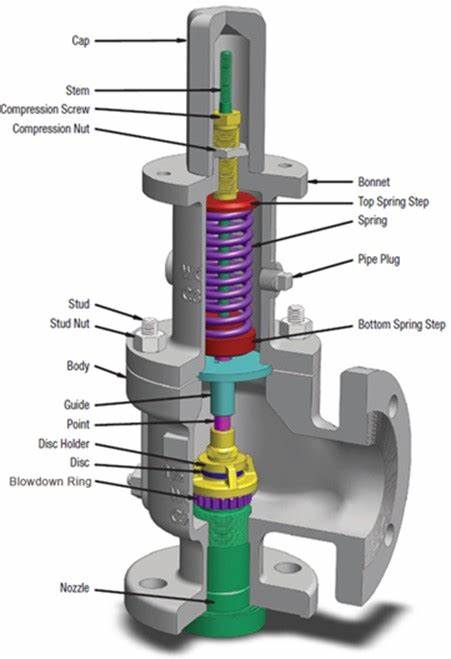
In the load spring safety valve, the valve closing pressure or spring force is applied by the coil spring under the pressure of the adjusting screw. The spring force is transferred to the disc through the stem. As long as the spring force is greater than the force generated at the inlet of the safety valve, the valve disc will seal the nozzle. The following figure shows the expanded nozzle and disc area of the relief valve at the pressure acting on the disc.
According to the preset conditions, the safety valve will open at the preset pressure. The spring force FS is applied in the closing direction, and the force FP generated by the pressure at the inlet of the safety valve is applied in the opening direction. When the pressure FS and medium force FP reach a balance, there is no force to place the valve disc on the valve seat; at this time, the safety valve will start to leak, and the sound of medium discharge can be seen or heard (the sound of medium just discharged).
Before the safety valve is obviously opened, the pressure at the valve inlet must be increased above the set pressure. Due to the flow restriction between the disc and the adjusting ring, the pressure gradually increases in this so-called mixing chamber. This pressure now acts on the expanded disc area, further increasing the pressure FP, which overcomes the additional force required to enter a compression spring. The valve will open quickly with a “bang” and in most cases it will be fully open. Overpressure refers to the pressure increase beyond the necessary set pressure of the safety valve to achieve full opening and full displacement of the valve. This overpressure is usually expressed as a percentage of the set pressure. The value is usually 10%, between 3% and 21% according to relevant specifications and applications.
In most applications, the proper size of safety valve will reduce the pressure when the vessel is discharged. The pressure of the vessel will drop at any subsequent point in time, but not later than the end of the pre-set condition. A decrease in pressure in the vessel will reduce the pressure FP. However, at set pressure, flow still acts on the expanded disc area, which opens the valve. Further pressure reduction is required before the spring force FS exceeds FP again and the relief valve begins to close again. Moreover, under the so-called reseating pressure, the disc will contact the nozzle again and the safety valve will close again. Return pressure difference refers to the difference between the set pressure of the safety valve and the return pressure, which is calculated as a percentage of the set pressure. According to the definition of relevant codes and standards, the reseating differential pressure is generally – 7% to – 10%, and it is – 4% to – 20% according to relevant codes and services (steam, gas or liquid).
API 526 safety valve series has a down regulating ring, and its set pressure is defined as the set pressure of the valve when the pressure reaches the initial discharge sound.
It is important to understand that the operating pressure of the protected equipment should be less than the reseating pressure of the safety valve. Most manufacturers and relevant codes and standards recommend that the difference between the reseating pressure and the operating pressure of 3% – 5% can achieve reasonable adjustment of the valve seat, and can again achieve good tightness of the valve seat.
Because the area of the pressure chamber is larger than the area of the main valve seat, the closing pressure is larger than the opening pressure. This allows the main valve to close tightly.
When the pressure reaches the set pressure, the pilot relief valve is activated. The medium will no longer lead to the pressure chamber (see Figure). This prevents further pressure rise in the pressure chamber.
At the same time, the pressure of the pressure chamber is discharged. Results the closing pressure of the main valve disappeared, which provided the precondition for the system overpressure to push the main valve to open.
The main valve is open. According to the design of pilot safety valve, there are two opening modes of safety valve, one is quick and thorough (quick opening action), the other is gradual and local (regulating action).
When the pressure in the pressure chamber increases, the main valve can be closed again through quick and thorough (quick opening action) or gradual local


 8613371530291