
boiler safety valve sizing price

Fired pressure vessels shall be fitted with safety relieving devices with sufficient capacity to relieve all vapor that may be generated in the vessels during normal operation. The safety relieving devices shall be fitted with proper controls to ensure safe operation.
To eliminate the necessity of shutting the system down for the inspection, a three-way stop valve may be installed under 2 safety valves, each with the required relieving capacity, installed so that both safety valves cannot be closed off from the vaporizer at the same time. Alternatively may 2 or more separate safety valves be installed with individual shutoff valves, in which case the shutoff valve stems is mechanically interconnected in a manner that allow full required flow capacity at all times.

A safety valve must always be sized and able to vent any source of steam so that the pressure within the protected apparatus cannot exceed the maximum allowable accumulated pressure (MAAP). This not only means that the valve has to be positioned correctly, but that it is also correctly set. The safety valve must then also be sized correctly, enabling it to pass the required amount of steam at the required pressure under all possible fault conditions.
Once the type of safety valve has been established, along with its set pressure and its position in the system, it is necessary to calculate the required discharge capacity of the valve. Once this is known, the required orifice area and nominal size can be determined using the manufacturer’s specifications.
In order to establish the maximum capacity required, the potential flow through all the relevant branches, upstream of the valve, need to be considered.
In applications where there is more than one possible flow path, the sizing of the safety valve becomes more complicated, as there may be a number of alternative methods of determining its size. Where more than one potential flow path exists, the following alternatives should be considered:
This choice is determined by the risk of two or more devices failing simultaneously. If there is the slightest chance that this may occur, the valve must be sized to allow the combined flows of the failed devices to be discharged. However, where the risk is negligible, cost advantages may dictate that the valve should only be sized on the highest fault flow. The choice of method ultimately lies with the company responsible for insuring the plant.
For example, consider the pressure vessel and automatic pump-trap (APT) system as shown in Figure 9.4.1. The unlikely situation is that both the APT and pressure reducing valve (PRV ‘A’) could fail simultaneously. The discharge capacity of safety valve ‘A’ would either be the fault load of the largest PRV, or alternatively, the combined fault load of both the APT and PRV ‘A’.
This document recommends that where multiple flow paths exist, any relevant safety valve should, at all times, be sized on the possibility that relevant upstream pressure control valves may fail simultaneously.
The supply pressure of this system (Figure 9.4.2) is limited by an upstream safety valve with a set pressure of 11.6 bar g. The fault flow through the PRV can be determined using the steam mass flow equation (Equation 3.21.2):
Once the fault load has been determined, it is usually sufficient to size the safety valve using the manufacturer’s capacity charts. A typical example of a capacity chart is shown in Figure 9.4.3. By knowing the required set pressure and discharge capacity, it is possible to select a suitable nominal size. In this example, the set pressure is 4 bar g and the fault flow is 953 kg/h. A DN32/50 safety valve is required with a capacity of 1 284 kg/h.
Where sizing charts are not available or do not cater for particular fluids or conditions, such as backpressure, high viscosity or two-phase flow, it may be necessary to calculate the minimum required orifice area. Methods for doing this are outlined in the appropriate governing standards, such as:
Coefficients of discharge are specific to any particular safety valve range and will be approved by the manufacturer. If the valve is independently approved, it is given a ‘certified coefficient of discharge’.
This figure is often derated by further multiplying it by a safety factor 0.9, to give a derated coefficient of discharge. Derated coefficient of discharge is termed Kdr= Kd x 0.9
Critical and sub-critical flow - the flow of gas or vapour through an orifice, such as the flow area of a safety valve, increases as the downstream pressure is decreased. This holds true until the critical pressure is reached, and critical flow is achieved. At this point, any further decrease in the downstream pressure will not result in any further increase in flow.
A relationship (called the critical pressure ratio) exists between the critical pressure and the actual relieving pressure, and, for gases flowing through safety valves, is shown by Equation 9.4.2.
Overpressure - Before sizing, the design overpressure of the valve must be established. It is not permitted to calculate the capacity of the valve at a lower overpressure than that at which the coefficient of discharge was established. It is however, permitted to use a higher overpressure (see Table 9.2.1, Module 9.2, for typical overpressure values). For DIN type full lift (Vollhub) valves, the design lift must be achieved at 5% overpressure, but for sizing purposes, an overpressure value of 10% may be used.
For liquid applications, the overpressure is 10% according to AD-Merkblatt A2, DIN 3320, TRD 421 and ASME, but for non-certified ASME valves, it is quite common for a figure of 25% to be used.
Backpressure - The sizing calculations in the AD-Merkblatt A2, DIN 3320 and TRD 421 standards account for backpressure in the outflow function,(Ψ), which includes a backpressure correction.
Two-phase flow - When sizing safety valves for boiling liquids (e.g. hot water) consideration must be given to vaporisation (flashing) during discharge. It is assumed that the medium is in liquid state when the safety valve is closed and that, when the safety valve opens, part of the liquid vaporises due to the drop in pressure through the safety valve. The resulting flow is referred to as two-phase flow.
The required flow area has to be calculated for the liquid and vapour components of the discharged fluid. The sum of these two areas is then used to select the appropriate orifice size from the chosen valve range. (see Example 9.4.3)
Many standards do not actually specify sizing formula for two-phase flow and recommend that the manufacturer be contacted directly for advice in these instances.
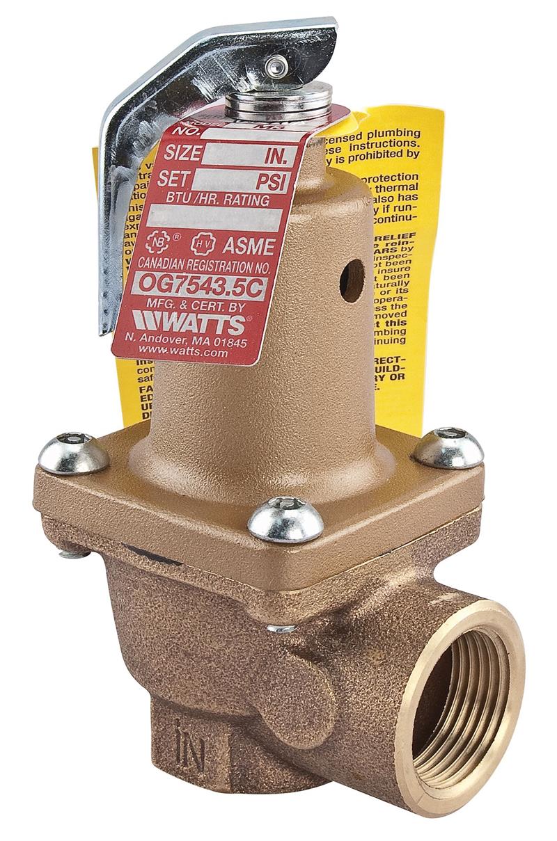
A safety valve is a valve that acts as a fail-safe. An example of safety valve is a pressure relief valve (PRV), which automatically releases a substance from a boiler, pressure vessel, or other system, when the pressure or temperature exceeds preset limits Safety valves are used to prevent pressure increases, leading to malfunctions, fire hazards, or explosions

Manufacturer of a wide range of products which include boiler safety valve, safety valve-pop type, pressure safety valve, spring loaded safety valve, safety relief valve and ibr safety valve.
ConnectionThreaded and Flanged EndsWe are the manufacturer, Supplier, and Exporter of Boiler Safety Valve from Chennai -India to Globally. These Safety Valves are Used to release the excess pressure inside the Boiler, High-Pressure Tanks, nd Vessels. So that Pressure can be maintained uniformly. we are manufacturer of valves like: Pressure Relief Valves, Safety relief Valves, Vacuum Relief Valve, Pressure cum vacuum relief valve, Breather valves.
Certificate-ApprovalISO, IBR, IRS, ATEX, TUV, BV, SGSWe are the manufacturer, supplier, and exporter of Safety Valves from Chennai-India to Globally. Used for controlling excess pressures, their precision construction standards make them extensively used in equipment like pressure vessels, pipelines & reactors.We have good infrastructure facility for EXPORT
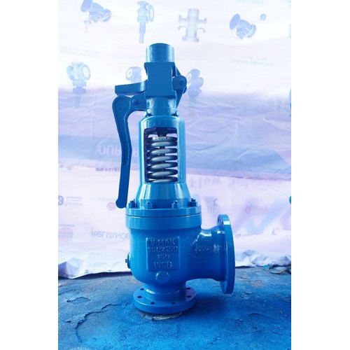
LeverPlain and Packed LeverBEEKAY brand Safety Valve, Safety Relief Valve, pressure Safety Valves are manufactured by LEVEL AND FLOW CONTROL ENGINEERS in India. Pressure Safety Valve can safeguard the tanks, vessels, boilers, and other capital equipments. when the pressure is esceed the limit valve will open automatically and release the excess pressure.we are expecting enquiry and orders from all over the world.
Accumulation0 to 10%LFCE Spring Loaded Safety Valve, Safety Relief Valves and Pressure Relief Valves are high performance and cost effective. Based on client request we can ready to supply valves with 0 to 5% accumulation and blowdown.Valve size : 1/4" to 12"
Country of OrginIndiaBEEKAY brand Safety Valve, Safety Relief Valve are manufactured by Level and Flow Control Engineers in INDIA. Valves are 100% safe and accuracy for Set pressure and Re-set pressures. Valves are mounted on pipelines, tanks, vessels and reactors to safeguard the capital equipments.We have already exported our range of products to all over the world like UAE, Middle East, Germany, Italay, Australlia, Malysia, Thailand, Indonesia, Philipines, Burunei, Srilanka, Pakistan, Netherland and many more
Flange Ratings150, 300, 600, 900, 1500 lbs RatingsLFCE Manufacturing, supplying, Exporting IBR Certified Safety Valves for Boilers, Deareators, LP, HP Heaters, Condensate Tanks and Vessels. We can able to supply the valves size from 25NB to 300NB and the Pressure Rating 150 lbs to 1500 lbs
We are expecting enquiry and orders from all over the world. Our valves and range of products are well exported to UAE, MIddle East, Thailand, Indonesia, Mayanmar, Vietnam, Srilanka, Malaysia, Singapore, Philipines, Australlia, Netherland, Italy, UAE, South African Countires.
Country of OriginMade in IndiaLFCE manufacturing, supplying, EXPORTING Safety Valve, Pressure Relief Valves with Lever and Plain types.We can able to supply CS, SS, DSS, SDSS, Alloy Steel grade of Materials with Max. of Pressure of 150 barValve size from 15NB to 200NBWe are expecting good enquiry and orders from all over the globe.
Rust ResistanceYesLFCE manufacturing and supplying Beekay brand Brass Safety Valves, Safety Relief Valves, Pressure Relief Valves fo the pressure vessels and Air Receivers. When the pressure is exceed the limit then the valve will open automatically and safeguard the capital equipments.Our brand Beekay is well known in the global market. Already we exported our range of products to all over the world :- UAE, Middle East, South Africa, Zimbawe, Zambia, Kenya, Oman, Saudi Arabia, Thailand, Indonesia, Philipines, Burunei, Srilanka, Pakistan, Hongkong, Netherland, Italay and many more
Flange StandardsANSI, BS, DIN, JS, IS, ASMELFCE manufacturing and EXPORTING Low Pressure, Medium Pressure, High Pressure Safety Valves, Safety Relief Valves for the Process Industries and Hydro Carbon Projects.Our Valves are manufactured and tested as per API StandardsWe are expecting enquiry/orders from all over the world.
Pressure relief valves are used to protect equipment from excessive overpressure. Properly sized relief valves will provide the required protection, while also avoiding issues with excessive flow rates, including: possible valve damage, impaired performance, undersized discharge piping and effluent handling systems, and higher costs.
Many scenarios can result in an increased vessel pressure, and each scenario may result in a different valve size. It is generally recommended to perform multiple case studies to find the most conservative sizing. Some typical cases include:
In any of these scenarios, the pressure will increase until a predetermined relief pressure is reached, at which point the relief pressure valve will open, decreasing the pressure after the turnaround time. The first step in sizing a Relief Valve in ProMax is to determine which scenario you are interested in modeling.
The Relief Valve Sizing in ProMax is performed as a stream analysis. Any stream in ProMax may have one or more Relief Valve Sizing Analyses added, so multiple cases can be studied in a single stream if desired.
There are many different standards for Relief Valve Sizing, each applying different assumptions, thus giving different results. For instance, API 520, one of the most cited standards, assumes both a mechanical and thermodynamic equilibrium, and constant phase properties during relief. Alternatively, the EN ISA 4126 standard accounts for thermodynamic non-equilibrium. ProMax currently supports six different sets of Relief Valve Sizing Standards:
Next, an appropriate relief type must be selected, as sizing depends on the type of relief device selected. The operation of conventional spring-loaded pressure relief valve is based on a force balance: the spring-load is preset to apply a force opposite in amount to the pressure force exerted by the fluid on the other side when it is at the set pressure. When the fluid pressure exceeds the set pressure, the pressure force overcomes the spring force, and the valve opens. Any back pressure (downstream pressure) is additive to the spring force; if this back pressure varies, then the pressure at which the valve opens will vary. Bellows are used to maintain a constant relief pressure despite back pressure variations. Rupture disc relief valves do not reclose after activation; preference should usually be given to reclosing relief devices for both safety and reliability. The most common valve types include:
Balanced Bellows- spring loaded pressure relief valve that incorporates a bellows for minimizing the effect of back pressure on the operational characteristics of the valve.
Pilot Operated- a pressure relief valve in which the major relieving device or main valve is combined with and controlled by a self-actuated auxiliary pressure relief valve (pilot).
The Relief Temperature is determined by which pressure relief scenario you have chosen to model, and should be the temperature of the fluid at the time that the valve is expected to open. ProMax assumes that the Relief Temperature will be the current stream temperature, however, if your particular scenario requires that this be adjusted, it can be overwritten directly in the analysis dialog.
The Over Pressure is usually expressed as a percentage of the Set Pressure. For spring-operated relief valves, a small amount of leakage occurs at 92-95% of theSet Pressure, and sufficient Over Pressure is necessary to achieve full lift. ASME-certified relief valves are required to reach full-rated capacity at 10% or less overpressure.
Once you’ve determined your emergency scenario, and specified the relieving conditions and flowrate, and the appropriate standard, ProMax will calculate the Effective Discharge Area. This value is used to select the appropriately sized Pressure Relief Valve.
Although an orifice is often used to describe the minimum flow area constricted in the valve, the geometry and relief area calculations are more appropriately modeled based on an ideal (isentropic) nozzle. The expression for the mass flux (Gn) in an ideal nozzle is obtained directly from Bernoulli’s equation in the nozzle:
distribution of fluid phases, interaction, and transformation of the phases, sizing a two-phase relief scenario is considerably more complex than single-phase. The Mass Flux calculation varies depending on the relieving fluid type:
This type of flow is often encountered at metering devices in chemical processing and in relief valve sizing applications where both non-condensable and condensable (flashing) components
This term is an estimation used in sizing pressure relief valves for two-phase liquid/vapor applications when the system has less than 0.1 wt% H2, a nominal boiling range less than 150°F, and
As such, there are multiple methods of approximating the latent heat, and the Relief Valve Sizing analysis follows the methodology of the standards. For example, the API 520 standard defines “latent heat” as
Darby, R., Meiller, P. R., Stockton, J. R. (2001). Select the Best Model for Two-Phase Relief Sizing, Chemical Engineering Progress, Vol.97, No.5, pp 56.

Relief valves are designed to open at a preset pressure (or temperature) level and relieve the system when it has exceeded the desired level. The valve"s relief of elevated liquid, gas, or steam pressures prevents damage to the system. We offer a wide selection of relief valves for any application.

Pressure Relief ValvePioneers in the industry, we offer boiler safety valve, angle safety valve, pilot operated valve, clean steam pressure relief valve, pop safety valve and fire protection pressure relief valve from India.


 8613371530291