
boiler safety valve sizing quotation
The main purpose of a safety valve is to prevent the pressure in a system to exceed the certification pressure. Above certification pressure, no one can guaranty the systems safety - and especially for a steam system with very hot gas with huge amount of latent heat, the consequences can be dramatically.
The size of the safety valve depends primarily on the maximum boiler output and the operation pressure of the system. The safety valve shall as minimum have the evacuation capacity of all the vapor the boiler can produce running at full power at working (or certification) pressure.
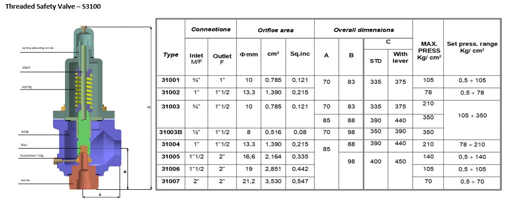
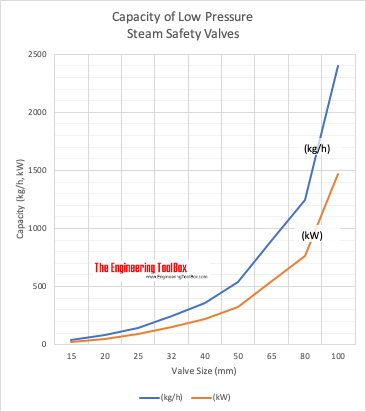
The table below can be used to select a typical safety valve based on boiler output. Before final design, always consult the manufactures documentation.
Note! The table above is based on low pressure steam of 100 kN/m2 (1 bar)or 15 psiin imperial units. Latent heat of saturated steam is 2201 kJ/kg (945 Btu/lb). 1 N/m2 = 1 Pa = 1.4504 x 10⁻⁴ lb/in2 (psi) = 10-5 bar For higher pressure, steam is compressed and require less volume - required size of the valve reduced
Above certification pressure no one can guaranty the systems safety - and especially for a steam system with a very hot gas with a huge amount of latent heat the consequence with a failure can be dramatically.
The size of a safety valve depends primarily on the maximum boiler output and the operation pressure of the system. The safety valve must as minimum have the evacuation capacity of all the vapor the boiler can produce running at full power at the working (or certification) pressure. for a higher pressure the steam is compressed and requires less volume and the size of the valve can be reduced
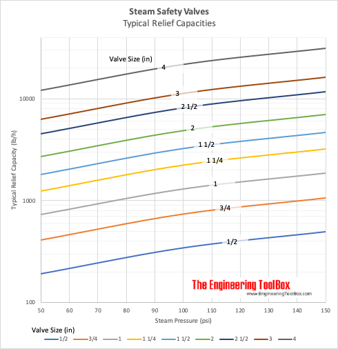
The tables below can be used to select a typical safety valve in a high pressure system. Before the final design - always consult manufacturing documentation.
Boiler explosions have been responsible for widespread damage to companies throughout the years, and that’s why today’s boilers are equipped with safety valves and/or relief valves. Boiler safety valves are designed to prevent excess pressure, which is usually responsible for those devastating explosions. That said, to ensure that boiler safety valves are working properly and providing adequate protection, they must meet regulatory specifications and require ongoing maintenance and periodic testing. Without these precautions, malfunctioning safety valves may fail, resulting in potentially disastrous consequences.
Boiler safety valves are activated by upstream pressure. If the pressure exceeds a defined threshold, the valve activates and automatically releases pressure. Typically used for gas or vapor service, boiler safety valves pop fully open once a pressure threshold is reached and remain open until the boiler pressure reaches a pre-defined, safe lower pressure.
Boiler relief valves serve the same purpose – automatically lowering boiler pressure – but they function a bit differently than safety valves. A relief valve doesn’t open fully when pressure exceeds a defined threshold; instead, it opens gradually when the pressure threshold is exceeded and closes gradually until the lower, safe threshold is reached. Boiler relief valves are typically used for liquid service.
There are also devices known as “safety relief valves” which have the characteristics of both types discussed above. Safety relief valves can be used for either liquid or gas or vapor service.
Nameplates must be fastened securely and permanently to the safety valve and remain readable throughout the lifespan of the valve, so durability is key.
The National Board of Boiler and Pressure Vessel Inspectors offers guidance and recommendations on boiler and pressure vessel safety rules and regulations. However, most individual states set forth their own rules and regulations, and while they may be similar across states, it’s important to ensure that your boiler safety valves meet all state and local regulatory requirements.
The National Board published NB-131, Recommended Boiler and Pressure Vessel Safety Legislation, and NB-132, Recommended Administrative Boiler and Pressure Vessel Safety Rules and Regulationsin order to provide guidance and encourage the development of crucial safety laws in jurisdictions that currently have no laws in place for the “proper construction, installation, inspection, operation, maintenance, alterations, and repairs” necessary to protect workers and the public from dangerous boiler and pressure vessel explosions that may occur without these safeguards in place.
The American Society of Mechanical Engineers (ASME) governs the code that establishes guidelines and requirements for safety valves. Note that it’s up to plant personnel to familiarize themselves with the requirements and understand which parts of the code apply to specific parts of the plant’s steam systems.
High steam capacity requirements, physical or economic constraints may make the use of a single safety valve impossible. In these cases, using multiple safety valves on the same system is considered an acceptable practice, provided that proper sizing and installation requirements are met – including an appropriately sized vent pipe that accounts for the total steam venting capacity of all valves when open at the same time.
The lowest rating (MAWP or maximum allowable working pressure) should always be used among all safety devices within a system, including boilers, pressure vessels, and equipment piping systems, to determine the safety valve set pressure.
Avoid isolating safety valves from the system, such as by installing intervening shut-off valves located between the steam component or system and the inlet.
Contact the valve supplier immediately for any safety valve with a broken wire seal, as this indicates that the valve is unsafe for use. Safety valves are sealed and certified in order to prevent tampering that can prevent proper function.
Avoid attaching vent discharge piping directly to a safety valve, which may place unnecessary weight and additional stress on the valve, altering the set pressure.
A safety valve must always be sized and able to vent any source of steam so that the pressure within the protected apparatus cannot exceed the maximum allowable accumulated pressure (MAAP). This not only means that the valve has to be positioned correctly, but that it is also correctly set. The safety valve must then also be sized correctly, enabling it to pass the required amount of steam at the required pressure under all possible fault conditions.
Once the type of safety valve has been established, along with its set pressure and its position in the system, it is necessary to calculate the required discharge capacity of the valve. Once this is known, the required orifice area and nominal size can be determined using the manufacturer’s specifications.
In order to establish the maximum capacity required, the potential flow through all the relevant branches, upstream of the valve, need to be considered.
In applications where there is more than one possible flow path, the sizing of the safety valve becomes more complicated, as there may be a number of alternative methods of determining its size. Where more than one potential flow path exists, the following alternatives should be considered:
This choice is determined by the risk of two or more devices failing simultaneously. If there is the slightest chance that this may occur, the valve must be sized to allow the combined flows of the failed devices to be discharged. However, where the risk is negligible, cost advantages may dictate that the valve should only be sized on the highest fault flow. The choice of method ultimately lies with the company responsible for insuring the plant.
For example, consider the pressure vessel and automatic pump-trap (APT) system as shown in Figure 9.4.1. The unlikely situation is that both the APT and pressure reducing valve (PRV ‘A’) could fail simultaneously. The discharge capacity of safety valve ‘A’ would either be the fault load of the largest PRV, or alternatively, the combined fault load of both the APT and PRV ‘A’.
This document recommends that where multiple flow paths exist, any relevant safety valve should, at all times, be sized on the possibility that relevant upstream pressure control valves may fail simultaneously.
The supply pressure of this system (Figure 9.4.2) is limited by an upstream safety valve with a set pressure of 11.6 bar g. The fault flow through the PRV can be determined using the steam mass flow equation (Equation 3.21.2):
Once the fault load has been determined, it is usually sufficient to size the safety valve using the manufacturer’s capacity charts. A typical example of a capacity chart is shown in Figure 9.4.3. By knowing the required set pressure and discharge capacity, it is possible to select a suitable nominal size. In this example, the set pressure is 4 bar g and the fault flow is 953 kg/h. A DN32/50 safety valve is required with a capacity of 1 284 kg/h.
Where sizing charts are not available or do not cater for particular fluids or conditions, such as backpressure, high viscosity or two-phase flow, it may be necessary to calculate the minimum required orifice area. Methods for doing this are outlined in the appropriate governing standards, such as:
Coefficients of discharge are specific to any particular safety valve range and will be approved by the manufacturer. If the valve is independently approved, it is given a ‘certified coefficient of discharge’.
This figure is often derated by further multiplying it by a safety factor 0.9, to give a derated coefficient of discharge. Derated coefficient of discharge is termed Kdr= Kd x 0.9
Critical and sub-critical flow - the flow of gas or vapour through an orifice, such as the flow area of a safety valve, increases as the downstream pressure is decreased. This holds true until the critical pressure is reached, and critical flow is achieved. At this point, any further decrease in the downstream pressure will not result in any further increase in flow.
A relationship (called the critical pressure ratio) exists between the critical pressure and the actual relieving pressure, and, for gases flowing through safety valves, is shown by Equation 9.4.2.
Overpressure - Before sizing, the design overpressure of the valve must be established. It is not permitted to calculate the capacity of the valve at a lower overpressure than that at which the coefficient of discharge was established. It is however, permitted to use a higher overpressure (see Table 9.2.1, Module 9.2, for typical overpressure values). For DIN type full lift (Vollhub) valves, the design lift must be achieved at 5% overpressure, but for sizing purposes, an overpressure value of 10% may be used.
For liquid applications, the overpressure is 10% according to AD-Merkblatt A2, DIN 3320, TRD 421 and ASME, but for non-certified ASME valves, it is quite common for a figure of 25% to be used.
Backpressure - The sizing calculations in the AD-Merkblatt A2, DIN 3320 and TRD 421 standards account for backpressure in the outflow function,(Ψ), which includes a backpressure correction.
Two-phase flow - When sizing safety valves for boiling liquids (e.g. hot water) consideration must be given to vaporisation (flashing) during discharge. It is assumed that the medium is in liquid state when the safety valve is closed and that, when the safety valve opens, part of the liquid vaporises due to the drop in pressure through the safety valve. The resulting flow is referred to as two-phase flow.
The required flow area has to be calculated for the liquid and vapour components of the discharged fluid. The sum of these two areas is then used to select the appropriate orifice size from the chosen valve range. (see Example 9.4.3)
Many standards do not actually specify sizing formula for two-phase flow and recommend that the manufacturer be contacted directly for advice in these instances.

When you need it: New construction, process conditions have changed, your valve is not performing as you expect, you want to consider modifications, or you just aren’t sure what you need. Our engineering team is available to assist with sizing and selection to get you the valve you need.
Automatic control valves must be sized to adequately control the process application for which it is intended. With nominal process data, calculations are performed to determine the flow capacity needed for the application, and that required capacity is matched to a type and size of valve and its “Cv”, or flow coefficient. If not properly sized, a control valve may not pass the required flow or may not operate in a range needed to effectively control the process.
Much like the control valve, the actuator must be sized to match the amount of force required to operate the valve. Without proper sizing, an actuator can be sluggish and not respond adequately to control signal changes, resulting in instability of the process being controlled. A missized actuator can also keep the valve from attaining its designed shutoff classification, and objectionable leakage may occur.
Valve type and size for the application are selected by an application engineer once the required flow capacities are calculated. Also essential is specifying the appropriate materials of construction of the process wetted parts: trim, valve body/bonnet, packing.

Accurately size and select a pressure relief valves for various process applications using SizeMaster™, a web-based engineering software tool. The SizeMaster™ software brings unprecedented integration of recognized and generally accepted good engineering practices (RAGAGEP) to the task of sizing and selecting pressure relief valves.
Accessing the SizeMaster™ sizing tool through one’s modern web browser, a user can perform a steady-state sizing analysis by first defining at least one, if not all, of the recommended overpressure failure scenarios identified within the API 521 Standard and then calculating the required discharge area to satisfy the upset conditions. Design details such as relieving conditions, fluid characteristics, and sound engineering principles are supplied to the software for such scenarios like fire, thermal expansion, control valve failure, and tube rupture. Suitable candidate Farris pressure relief valve(s) are presented to the user for selection based on the supplied application requirements which then can be further customized and configured for a specific criterion.
All sizing equations and selection algorithms are based on ASME Code requirements, API standards and best engineering practice as determined byFarris Engineering. The equations and flow algorithms are internally calculated within an innovative worksheet engine which checks selected conditions and any intermediate calculations against the constraints of industry standards, informing the user of any non-compliance issues it encounters. Using supplied sizing conditions and application-specific details, suitable candidate valve(s) are cross-checked against their appropriate temperature and pressure tables including any backpressure constraints. Once the software determines the orifice area required to relieve the supplied overpressure scenario(s), SizeMaster™ recommends an optimum Farris pressure relief valve series and orifice size. The user can further customize its materials, soft goods, and other options and accessories to meet their facility and device needs.
All application details, sizing equations, and other overpressure scenario parameters can be generated in different data formats (i.e. XLS, HTML, PDF, etc.) and extracted from the program.
SizeMaster includes catalog information forFarris 2400, 2600, 2700, 3800, 6400/6600, 4200, 1890, 1896, and 4700seriespressure relief valves,including black and white cross-section dimensional drawings. The registered user can select and customize a candidate Farris model number, SizeMaster™ will ensure a valve is suitable for the supplied process parameters (such as a liquid-trim valve for a vapor scenario), and on-line help is available to assist in the determination of each of the digits of the Farris model number configuration. SizeMaster™ can manage the sizing and selection work-flow process for jobs/plants, from request for quotation through order generation.
Whether the user is quoting safety valves for a large-scale Job/Plant or performing a single yet fast Quick Sizeoption, SizeMaster™ makes the task of sizing and selecting pressure relief valves straight-forward and globally accessible. The design of this web-based software allows for the development team to automatically deploy updated versions of the tool to remain up-to-date with the latest changes in industry best practices and new product features and offerings.

Years ago, it was not uncommon to read news about tragic boiler explosions, sometimes resulting in mass destruction. Today, boilers are equipped with important safety devises to help protect against these types of catastrophes. Let’s take a look at the most critical of these devices: the safety valve.
The safety valve is one of the most important safety devices in a steam system. Safety valves provide a measure of security for plant operators and equipment from over pressure conditions. The main function of a safety valve is to relieve pressure. It is located on the boiler steam drum, and will automatically open when the pressure of the inlet side of the valve increases past the preset pressure. All boilers are required by ASME code to have at least one safety valve, dependent upon the maximum flow capacity (MFC) of the boiler. The total capacity of the safety valve at the set point must exceed the steam control valve’s MFC if the steam valve were to fail to open. In most cases, two safety valves per boiler are required, and a third may be needed if they do not exceed the MFC.
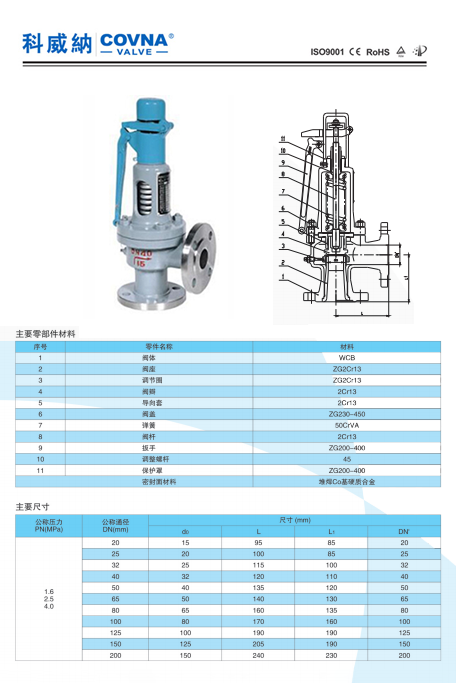
There are three main parts to the safety valve: nozzle, disc, and spring. Pressurized steam enters the valve through the nozzle and is then threaded to the boiler. The disc is the lid to the nozzle, which opens or closes depending on the pressure coming from the boiler. The spring is the pressure controller.
As a boiler starts to over pressure, the nozzle will start to receive a higher pressure coming from the inlet side of the valve, and will start to sound like it is simmering. When the pressure becomes higher than the predetermined pressure of the spring, the disc will start to lift and release the steam, creating a “pop” sound. After it has released and the steam and pressure drops below the set pressure of the valve, the spring will close the disc. Once the safety valve has popped, it is important to check the valve to make sure it is not damaged and is working properly.
A safety valve is usually referred to as the last line of safety defense. Without safety valves, the boiler can exceed it’s maximum allowable working pressure (MAWP) and not only damage equipment, but also injure or kill plant operators that are close by. Many variables can cause a safety valve on a boiler to lift, such as a compressed air or electrical power failure to control instrumentation, or an imbalance of feedwater rate caused by an inadvertently shut or open isolation valve.
Once a safety valve has lifted, it is important to do a complete boiler inspection and confirm that there are no other boiler servicing issues. A safety valve should only do its job once; safety valves should not lift continuously. Lastly, it is important to have the safety valves fully repaired, cleaned and recertified with a National Board valve repair (VR) stamp as required by local code or jurisdiction. Safety valves are a critical component in a steam system, and must be maintained.
All of Nationwide Boiler’s rental boilers include on to two safety valves depending on the size; one set at design pressure and the other set slightly higher than design. By request, we can reset the safeties to a lower pressure if the application requires it. In addition, the valves are thoroughly checked after every rental and before going out to a new customer, and they are replaced and re-certified as needed.

Series 174A Boiler Pressure Relief Valves are used in hot water heating and domestic supply boiler applications to protect against excessive pressures on all types of hot water heating supply boiler equipment. They have a bronze body construction with NPT threaded female inlet and NPT threaded female outlet (drain) connections, non-metallic disc-to-metal seating, stainless steel spring, and test lever. Series 174A resists corrosive water conditions, sticking, and freezing, and it prevents water and sediment from being trapped in the seat. It is designed for emergency safety relief and shall not be used as an operating control. Standard Pressure Setting: 30psi (206.9 kPa). Pressure Range: In 5psi (34.5 kPa) increments from 30 to 150psi (2 to 10 bar) with corresponding high ratings from 650,000 to 14,370,000 BTU/hr.

Tired of keeping track of your valve inventory’s annual certification records? We offer complete management of your safety relief valves. With an inventory of repair parts and in stock relief valves of all sizes, we can respond to any customer emergency. We offer annual certification services as well as repair of all major brands, including Kunkle, Conbraco, Consolidated, Dresser, Apollo and more.

**Update to this article, June 7, 2022 : If you found this article helpful, here is a link to another article I recently found that does a nice job explaining the topic: ENGINEERS BEWARE: API vs ASME Relief Valve Orifice Size – Petro Chem Engineering (petrochemengg.com)
NOTE: this article is written to an audience that is familiar with PSVs, PSV sizing, and API and ASME standards at a basic level. I initially wrote this article in early 2017, and due to some great input and questions made significant revisions to increase clarity in mid-2018. I hope it is helpful to you, please send me a message with any comments/questions!
If you"ve ever sized/selected a Pressure Safety-Relief Valve (PSV) using vendor sizing programs or good-old hand calculations, you"ve probably run into a very strange anomaly: Why does a PSV orifice size change between American Petroleum Institute (API) and American Society of Mechanical Engineers (ASME) data sets? What is an "effective" orifice area? How do I know which standard to use when selecting a PSV?
Usually, this issue is one of curiosity and doesn"t affect the end result of what valve is chosen. Common practice is to default to API sizing equations and parameters, and only use ASME data sets for situations outside of the API letter-designations. But what if I told you that approach is likely causing you to oversize about 10% of your PSVs and their respective piping systems?
Too often, we leave that third part out of the process, and simply calculate relief loads and select valves using API techniques, without ever checking our selection against certified ASME data. Proper application of these standards is the first key point of this article:
Initial sizing and valve selection is done using API equations, and final valve selection and certification is done using ASME-certified coefficients and capacities.
When sizing a PSV, the sizing equations are always API 520. When a PSV is certified, it is always certified to ASME BPVC (whether one “selects” ASME certification or not!) It"s important to remember that the ASME BPVC is the "code", the standard to which we must design. API 520/526 are "recommended practices" which were developed to give engineers a tool to meet the ASME requirements. Another way to look at it: ASME BPVC sets the goal, API 520/526 provide the instructions, and ASME has the final say.
The BPVC is an enormous code, and not reviewed in detail here. On the subject of PSVs, it basically says that a PSV must be capable of relieving the required load, and it must be tested in a specific manner to be certified to do so. If a valve is tested per the specific directions in the BPVC, it will be ASME certified and receive an ASME UV stamp.
The first thing API does is attempt to standardize physical PSV sizes and design, and it does so in API RP 526, which is targeted at PSV manufacturers. API provides pre-defined valve sizes, with letter designations D through T (API 526). It also defines other details directed toward valve manufacturers (such as temperature ratings). All of this is intended as minimum design standards, and manufacturers are free to exceed these parameters as they wish.
The second thing API does is provide standardized equations and parameters to use when trying to figure out just what size of a PSV one needs for a particular scenario. The equations account for design parameters that ASME doesn"t speak to, such as specific fluid properties, backpressures, critical flow, two-phase flow, and many other aspects of fluid dynamics that will affect the ability of a particular valve to relieve a required load.
API sizing equations are by nature theoretical, standardized, and use default or "dummy" values for several sizing parameters that may or may not reflect the actual values for any specific valve.
API RP 520 very clearly talks about this, and emphasizes that the intended use of its equations is to determine a preliminary valve size, which should be verified with actual data. API intends PSV sizing to be a two-step process, but we are often unaware of this because we (gasp) don’t read the full standard, and/or rely solely on vendor sizing software that hides the iteration from us. See API 520, part 1, section 5.2 for further explanation.
When valves are built, they are built to the API RP 526 standard, however, as one might imagine, when valves are actually tested and certified, the results don’t match up identically to the theoretical values that were calculated. This is where API and ASME intersect; we switch from calculations (API) which were used as a basis to design the valve, to actual empirical data (ASME) to certify the valve. When a valve manufacturer gets the UV code stamp that certifies the valve orifice size and capacity, it is based on actual test results, not API sizing standards. And ASME (which came first) does not have tiered letter designations. The typical D, E, F, etc. sizes we refer to are strictly an API tool, and ASME’s capacity certifications are completely independent of them!
3. A third-party Engineer (you), trying to select a PSV, runs a sizing calculation using API 520 equations on ABC Valve Company"s sizing software, gets a result that requires 4.66in2 to relieve the load, and is now thoroughly confused on what size valve to select.
If one selects the API data set on the sizing software in this example, it will automatically eliminate N-orifice valves as an option, and bump the user up to a P-orifice. However, if one simply selects the ASME data set, the N-orifice valve magically reappears as an option. How can this be? Will the N-orifice work or not?
Digest that for a moment. If you’ve sized and purchased more than a dozen PSVs, chances are you have inadvertently selected a PSV a full size larger than you needed to, in a situation much like our example, simply because you chose a PSV based on its API “rating” rather than its real, certified, stamped ASME rating. If that was a small valve, impact was probably nil. But what if this happened on a valve that resulted in selecting a 8x10 PSV when you could have used a 6x8?
If you’re like me, that answer isn’t very satisfying. Why on earth is this so confusing? How can you simply hit a button on the sizing program and a different size of valve is suddenly acceptable? The key lies how the main coefficient of discharge, Kd, is handled, and how capacities are determined.
There are several K values used in API calculations, all of which have generic values defined in API 520 that can be used for preliminary sizing. These are the numbers used in initial sizing calculations to get us close, then (if we do this correctly) replaced with the actual/tested/empirical/ASME values when we get a certified valve. Remember, anytime you hear “certified” or “stamped”, think ASME.
Let’s take the numbers from the example above, which came from an attempt to size a valve for liquid relief. API says to use a value of Kd=0.65 for liquid relief. If one uses the API data set on the vendor software, then the calculation stops here, and you get a required area of 4.66in2. When you select a valve, you’re comparing that to the API effective (actual) area of an N orifice, which is 4.34 in2, which is obviously too small and you’d logically step up to a P orifice. However….
Remember that the API N-orifice area is just the benchmark, a minimum requirement, and may or may not (most likely not) reflect the actual area of a real-life PSV. Once a valve is selected, all of those K values and capacities should be replaced with actual ASME-certified K values, also determined by testing, that are specific to each valve model, and the calculations performed again.
Normally, ASME-certified K-values are smaller than the API dummy values, driving up the required orifice area. So valve manufacturers have to over-design their valves to make up for it, resulting in ASME-certified areas and capacities that typically exceed the benchmark API ones. The end result of all this?
It (almost) all boils down to one sneaky little sentence in the ASME BPVC which mandates a 10% safety factor on the empirically-determined Kd that “de-rates” the valve (see ASME BPVC Section VIII, UG-131.e.2). This tidbit seems to be a little-known fact that is key to proper PSV sizing and selection, because as engineers we often pile safety factors upon each other and oversize our equipment. I cannot highlight this enough:
I mentioned above that ASME K values are nearly always lower than API values, due to this 10% de-rating. The PSV in our example scenario has a determined Kd of 0.73, which is adjusted down by 10% for a final AMSE Kd of 0.66, slightly higher than the dummy API value (that just means that this particular valve proved it could do about 11% better than the minimum theoretical flow calculated by API when it was tested). So, for our valve in question, the Required ASME area is slightly less than the API area. This is atypical, but not unheard of, and again points to the importance of checking the ASME ratings of any valve you select, and comparing against the API benchmarks.
When you choose to use the ASME data on a specific valve, it’s not just the Kd sizing factor that changes; the actual orifice area and therefore the capacity of the valve also adjusts to empirical, certified values. You can generally expect both values to increase over the API values.
Why is this? Simply that any given real-world valve is usually over-designed so that it will meet and exceed the required minimum capacity of its corresponding API size. What a simple concept, but so often overlooked by engineers!
*Note: this is data from a real case; the specific PSV make/model is omitted. Did you catch the result? The actual, certified capacity of this valve is nearly 13% higher than the generic N-orifice valve, and that includes its 10% safety factor!
With this adjusted orifice area, we can compare to the ASME certified area (which is always going to be larger than the API area), and we have our final answer for the valve size. Often this will not result in a different choice of valve, but sometimes, as in the example case, it will allow us to use a valve with an API letter designation that did not appear large enough based on its API effective area. This can save time and money for our plants by preventing over-sizing valves, leading to smaller piping systems to support them. And remember, the ASME values are empirical and have a 10% safety factor built in, so we don’t need to worry about cutting the design too close; the conservatism is already built in to the method. We can choose the Brand X N-orifice valve and sleep well at night!
Avoid simply defaulting to the API data set for the final “rating” or data sheet when selecting a PSV. Use API sizing calculations as they are intended: for preliminary valve selection. Then switch to the ASME data set. This will often (but not always, remember, it"s valve-specific) result in two differences:
Closing notes: PSV sizing and selection is a big topic, and this article only addresses one issue. I have chosen to omit specific code references and quotations in an attempt to make this a general guideline that is useful for most engineers, not an interpretation of the codes. Many tangent issues can spin off from this article; I will be happy to help with any questions it may generate. Please email me any comments or suggestions, I welcome all input.

For the diverse requirements of our clients we are involved in offering an extensive range of Boiler Valve. These can withstand with extreme weather conditions and have high strength also. Our products are abrasion resistant in nature and are well known for their perfect finishing. Besides, these can also be quality tested onread more...
Owing to our expertise, we are distributing, trading, retailing, importing and supplying a wide assortment of Utam-Boiler Mountings. The offered mountings are developed using superior grade material and modish technology in synchronization with set norms of industry. In addition, offered mountings are widely acknowledged amongread more...


 8613371530291