
boiler safety valve testing factory

Safety valves are used in a variety of industrial applications to include air/gas, vapor, steam, and liquid service, among many more. These pressure relief valves are critical to the safe operation of our customer’s equipment and provide—as their name implies—a safety measure that can reduce the number of risks that can threaten both your personnel and facilities.
Millennium Power Services’ safety valve technicians will get your valves tested, repaired, and quickly set to the exact specifications. We serve as your knowledge partner and will also evaluate the repair condition of every valve and make recommendations as needed to help you make the best decisions.

Safety valves are used in a variety of applications, including air/gas, vapor, steam and liquid service. Flotech has been approved by the National Board of Boiler and Pressure Vessel Inspectors to perform safety and relief valve testing, repair and certification.
Our valve experts will focus on getting your valves tested, repaired and quickly set to the exact specifications. We evaluate the repair condition of every valve and will recommend the right solution to manage your maintenance program.

The Pressure Safety Valve Inspection article provides you information about inspection of pressure safety valve and pressure safety valve test in manufacturing shop as well as in operational plants.
Your pressure safety valve is a direct spring-loaded pressure-relief valve that is opened by the static pressure upstream of the valve and characterized by rapid opening or pop action.
Your construction code for pressure safety valve is API Standard 526 and covers the minimum requirements for design, materials, fabrication, inspection, testing, and commissioning.
These are:API Recommended Practice 520 for Sizing and SelectionAPI Recommended practice 521 Guideline for Pressure Relieving and Depressing SystemsAPI Recommended Practice 527 Seat Tightness of Pressure Relief Valves
For example in the state of Minnesota the ASME Code application and stamping for pressure vessel and boiler is mandatory which “U” and “S” symbols are designated for stamping on the nameplate.
For example if there is pressure vessel need to be installed in the state of Minnesota then the pressure vessel nameplate shall be U stamped and pressure vessel safety valve shall be UV stamped.
National Board Inspection Code (NBIC) have own certification scheme for pressure safety valves and using NB symbol. The NBIC code book for this certification is NB 18.
There are some other standards and codes which are used in pressure safety valve such as:ASME PTC 25 for pressure relief devices which majorly is used for assessment of testing facility and apparatus for safety valvesBS EN ISO 4126-1, 4126-2 and 4126-3 which is construction standard similar to API STD 526.
This API RP 527 might be used in conjunction of API RP 576 as testing procedure for seat tightness testing of pressure safety valve for periodical servicing and inspection.
These are only important points or summery of points for pressure safety valve in-service inspection and should not be assumed as pressure safety valve inspection procedure.
Pressure safety valve inspection procedure is comprehensive document which need to cover inspection methods to be employed, equipment and material to be used, qualification of inspection personnel involved and the sequence of the inspection activities as minimum.
You may use following content as summery of points for Pressure Safety Valve Inspection in operational plantDetermination pressure safety valve inspection interval based API STD 510 and API RP 576 requirementsInspection of inlet and outlet piping after pressure safety valve removal for any foulingInspection of pressure safety valve charge and discharge nozzles for possible deposit and corrosion productsTaking care for proper handling of pressure safety valves from unit to the valve shop. The detail of handling and transportation instruction is provided in API RP 576.Controlling of seals for being intact when the valves arrived to the valve shop.Making as received POP test and recording the relieving pressure.
If the POP pressure is higher than the set pressure the test need to be repeated and if in the second effort it was near to the set pressure it is because of deposit.If in the second effort it was not opened near to the set pressure either it was set wrongly or it was changed during the operationIf the pressure safety valve was not opened in 150% of set pressure it should be considered as stuck shut.If the pressure safety valve was opened below the set pressure the spring is weakenedMaking external visual inspection on pressure safety valve after POP test. The test need contain following item as minimum;the flanges for pitting and roughness
Making body wall thickness measurementDismantling of pressure safety valve if the result of as received POP test was not satisfactoryMaking detail and comprehensive visual and dimensional inspection on the dismantled valve parts (after cleaning)Making special attention to the dismantled valves seating surfaces inspection e.g. disk and seat for roughness, wear and damage which might cause valve leakage in serviceReplacing the damaged parts in dismantled valves based manufacture recommendation and API RP 576 requirementsMaking precise setting of the pressure safety valve after reassembly based manufacture recommendation or NB-18 requirements
Making at least two POP test after setting and making sure the deviation from set pressure is not more than 2 psi for valves with set pressure equal or less than 70 psi or 3% for valves with set pressure higher than 70 psiMaking valve tightness test for leakage purpose after approval of the setting pressure and POP tests. The test method and acceptance criteria must be according to the API RP 576.The API RP 527 also can be used for pressure safety valve tightness test.Recording and maintaining the inspection and testing results.

When it comes to understanding pressure relief valve testing requirements, there’s a lot of information out there, but not all of it seems conclusive. If you’re new to pressure relief valves or are getting started in a new industry, it can be tough to decipher what testing requirements your facility needs to meet.
While we can’t provide the specific testing requirements for every industry, we can offer a few general testing requirements, and point you in the right direction to find the information you need for your facility’s unique testing requirements:
It’s good to keep in mind that every industry and region has unique pressure relief valve testing requirements. Your facility may be required to just bench test pressure relief valves every five years, or you may have to test valves every year, but bench test and repair valves every three to five years. There is a large variance in the testing requirements for pressure relief and safety valves depending on your industry and your region. That said, there are a few general testing requirements we can look at to start with.
The National Board Inspection Code, created by the National Board of Boiler and Pressure Valve Inspectors, makes the following recommendations on the frequency of testing for safety and pressure relief valves, depending on the temperature, psi, and function of your boiler:
High-pressure steam boilers greater than 15 psi and less than 400 psi should be manually checked every 6 months and pressure tested annually to verify nameplate set pressure.
High-pressure steam boilers greater than 400 psi should be pressure tested to verify nameplate set pressure every three years, or as determined by operating experience as verified by testing history.
High-temperature hot water boilers operating at greater than 160 psi and/or 250° F should be pressure tested annually to verify nameplate set pressure.
It’s important to remember that these are general pressure valve testing recommendations. For specific requirements, you’ll have to verify your unique jurisdictional and industry code requirements. See the resources below for more information.
The National Board Inspection Code is an industry-recognized name offering quality information on pressure relief valve testing requirements. Here, you’ll find a wealth of information and testing best practices.
The ASME is another organization setting pressure relief valve testing requirements, and offering the necessary training engineers need to test and understand the testing procedures for pressure relief valves. In addition to testing requirements and standards, the ASME offers a variety of online courses on pressure relief valves, from fabrication and proper installation to inspection and repair.
For specific testing standards, it’s best to check with your industry and your regional jurisdiction. Pressure relief valve testing requirements can vary by state or region and are most often industry-specific. Check your industry’s standards, and check local code requirements to ensure your facility is adhering to the most relevant pressure relief valve testing requirements.
When you’re looking for the pressure relief valve testing requirements relevant to your facility, it’s important to understand the different testing methods that are available to you. It’s likely that regardless of your industry if you have safety and pressure relief valves in use at your facility, you’ll have to bench test those valves at least every five years.
In addition to those bench tests, though, you’ll also have to perform manual or on-site pressure relief valve testing. Here’s a quick look at the three most common pressure relief valve testing methods you’ll see when researching pressure relief valve testing requirements:
The most commonly mandated form of pressure relief valve testing, bench testing is unique in that it requires you completely shut down your facility’s system and remove all pressure relief valves. The valves are then transported to a lab where they are tested and repaired as necessary. Tested valves are then re-installed in your system.
Bench testing is the most involved method of pressure relief valve testing, but as this is how valves are tested when they’re manufactured, the industry considers this to be the most thorough testing method.
Inline testing is another accurate pressure relief valve testing method that doesn’t require the removal of valves or facility downtime. With inline safety relief valve testing equipment, a trained technician can test valves in the system to calculate the real setpoint of a valve in the system.
While inline testing cannot take the place of mandated bench testing, it is a more efficient form of testing for other regular testing requirements. Inline pressure relief valve testing is the ideal choice for any required testing that does not have to be bench testing, as it eliminates the need for downtime while still providing exceptionally accurate results.
Some pressure relief valve testing requirements will call for regular manual testing for freedom of operation. This is a basic test that can be done on-site. To complete an operated-in-place test, the test lever on the valve is manually activated. This test functions to ensure that the valve can open and shut tightly, but it does not verify at what pressure the valve opens and shuts. This is a test that may be required quarterly or bi-annually, to ensure the most basic functionality of safety relief valves.
Pressure relief valve testing is necessary for any facility with safety relief and pressure relief valves. For more information about the equipment you need for pressure relief valve testing, the profitability of certain testing methods, and more, head to the AccuTEST blog. There, you’ll find a variety of resources on everything from implementing inline safety relief valve testing to minimizing plant downtime.
If your company requires regular pressure relief valve testing, you might be interested in AccuTEST’s high-tech equipment. Offering inline testing with accurate, repeatable results, our system is the best on the market. See how our equipment works in real-time — schedule a live webinar demo today.
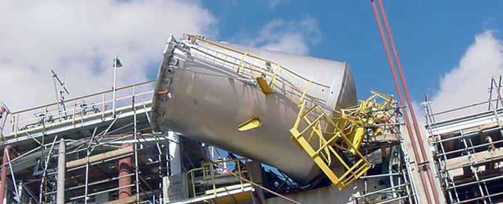
Safety is of the utmost importance when dealing with pressure relief valves. The valve is designed to limit system pressure, and it is critical that they remain in working order to prevent an explosion. Explosions have caused far too much damage in companies over the years, and though pressurized tanks and vessels are equipped with pressure relief vales to enhance safety, they can fail and result in disaster.
That’s also why knowing the correct way to test the valves is important. Ongoing maintenance and periodic testing of pressurized tanks and vessels and their pressure relief valves keeps them in working order and keep employees and their work environments safe. Pressure relief valves must be in good condition in order to automatically lower tank and vessel pressure; working valves open slowly when the pressure gets high enough to exceed the pressure threshold and then closes slowly until the unit reaches the low, safe threshold. To ensure the pressure relief valve is in good working condition, employees must follow best practices for testing them including:
If you consider testing pressure relief valves a maintenance task, you’ll be more likely to carry out regular testing and ensure the safety of your organization and the longevity of your
It’s important to note, however, that the American Society of Mechanical Engineers (ASME) and National Board Inspection Code (NBIC), as well as state and local jurisdictions, may set requirements for testing frequency. Companies are responsible for checking with these organizations to become familiar with the testing requirements. Consider the following NBIC recommendations on the frequency for testing relief valves:
High-pressure steam boilers greater than 15 psi and less than 400 psi – perform manual check every six months and pressure test annually to verify nameplate set pressure
High-pressure steam boilers 400 psi and greater – pressure test to verify nameplate set pressure every three years or as determined by operating experience as verified by testing history
High-temperature hot water boilers (greater than 160 psi and/or 250 degrees Fahrenheit) – pressure test annually to verify nameplate set pressure. For safety reasons, removal and testing on a test bench is recommended
When testing the pressure relief valve, raise and lower the test lever several times. The lever will come away from the brass stem and allow hot water to come out of the end of the drainpipe. The water should flow through the pipe, and then you should turn down the pressure to stop the leak, replace the lever, and then increase the pressure.
One of the most common problems you can address with regular testing is the buildup of mineral salt, rust, and corrosion. When buildup occurs, the valve will become non-operational; the result can be an explosion. Regular testing helps you discover these issues sooner so you can combat them and keep your boiler and valve functioning properly. If no water flows through the pipe, or if there is a trickle instead of a rush of water, look for debris that is preventing the valve from seating properly. You may be able to operate the test lever a few times to correct the issue. You will need to replace the valve if this test fails.
When testing relief valves, keep in mind that they have two basic functions. First, they will pop off when the pressure exceeds its safety threshold. The valve will pop off and open to exhaust the excess pressure until the tank’s pressure decreases to reach the set minimum pressure. After this blowdown process occurs, the valve should reset and automatically close. One important testing safety measure is to use a pressure indicator with a full-scale range higher than the pop-off pressure.
Thus, you need to be aware of the pop-off pressure point of whatever tank or vessel you test. You always should remain within the pressure limits of the test stand and ensure the test stand is assembled properly and proof pressure tested. Then, take steps to ensure the escaping pressure from the valve is directed away from the operator and that everyone involved in the test uses safety shields and wears safety eye protection.
After discharge – Because pressure relief valves are designed to open automatically to relieve pressure in your system and then close, they may be able to open and close multiple times during normal operation and testing. However, when a valve opens, debris may get into the valve seat and prevent the valve from closing properly. After discharge, check the valve for leakage. If the leakage exceeds the original settings, you need to repair the valve.
According to local jurisdictional requirements – Regulations are in place for various locations and industries that stipulate how long valves may operate before needing to be repair or replaced. State inspectors may require valves to be disassembled, inspected, repaired, and tested every five years, for instance. If you have smaller valves and applications, you can test the valve by lifting the test lever. However, you should do this approximately once a year. It’s important to note that ASME UG136A Section 3 requires valves to have a minimum of 75% operating pressure versus the set pressure of the valve for hand lifting to be performed for these types of tests.
Depending on their service and application– The service and application of a valve affect its lifespan. Valves used for clean service like steam typically last at least 20 years if they are not operated too close to the set point and are part of a preventive maintenance program. Conversely, valves used for services such as acid service, those that are operated too close to the set point, and those exposed to dirt or debris need to be replaced more often.
Pressure relief valves serve a critical role in protecting organizations and employees from explosions. Knowing how and when to test and repair or replace them is essential.

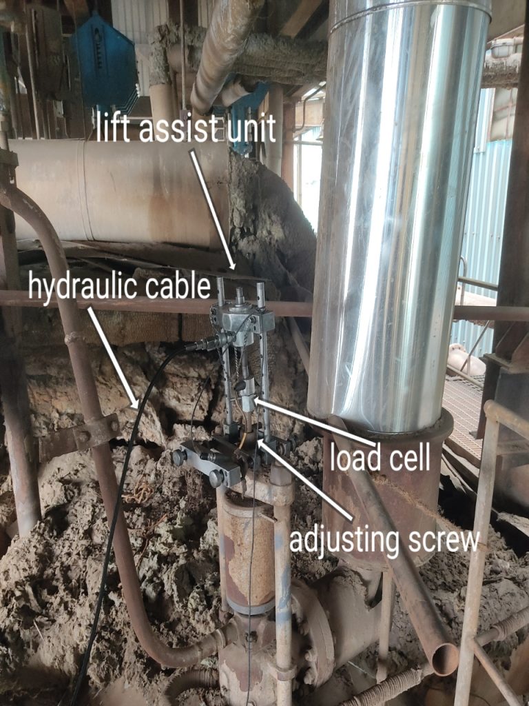
With an ever-increasing focus on reducing maintenance expenditure, there is a need for safety critical equipment to function reliably. With preventative maintenance on pressure safety valves (PSVs) being one of the more significant integrity costs, increasing efficiencies in this area is important, with potential for time savings and performance improvement.
The Pressure Safety Valve Manager digital tool is client-accessible and contains all the information used in the RBI, including the (pre-pop) results. Detailed tabs contain the PSV performance history for the asset(s). The tool may also communicate with the operator’s computerized maintenance management system (CMMS) to accurately relay, not only the performance history of each PSV, but also information useful for maintenance planning, such as shutdown requirements, online testing capabilities etc.
Pressure safety valves are designed to protect process piping and equipment in case of an overpressure event. TEAM Valve Solutions inspects, tests, repairs and re-certifies safety valves at 17 service centers across three continents, and in our fleet of mobile facilities, all of which are audited under the jurisdiction of relevant governing bodies.
Our solutions cover all major safety valve brands and support our customers through an inventory of spare parts and loose-assembled valves. In addition, our facilities are audited and governed by the National Board of Boiler and Pressure Vessel Inspectors. Testing, repair, and assembly are performed under license and guidelines of NBIC, and ASME Section I and VIII.
To ensure accurate in-line setpoint verification, TEAM Valve Solutions utilizes Trevitest, the pioneering system for validating safety valve performance in Conventional and Nuclear Power plants, as well as in other industrial process facilities.

Tired of keeping track of your valve inventory’s annual certification records? We offer complete management of your safety relief valves. With an inventory of repair parts and in stock relief valves of all sizes, we can respond to any customer emergency. We offer annual certification services as well as repair of all major brands, including Kunkle, Conbraco, Consolidated, Dresser, Apollo and more.
Safety valves are an arrangement or mechanism to release a substance from the concerned system in the event of pressure or temperature exceeding a particular preset limit. The systems in the context may be boilers, steam boilers, pressure vessels or other related systems. As per the mechanical arrangement, this one get fitted into the bigger picture (part of the bigger arrangement) called as PSV or PRV that is pressure safety or pressure relief valves.
This type of safety mechanism was largely implemented to counter the problem of accidental explosion of steam boilers. Initiated in the working of a steam digester, there were many methodologies that were then accommodated during the phase of the industrial revolution. And since then this safety mechanism has come a long way and now accommodates various other aspects.
These aspects like applications, performance criteria, ranges, nation based standards (countries like United States, European Union, Japan, South Korea provide different standards) etc. manage to differentiate or categorize this safety valve segment. So, there can be many different ways in which these safety valves get differentiated but a common range of bifurcation is as follows:
The American Society of Mechanical Engineers (ASME) I tap is a type of safety valve which opens with respect to 3% and 4% of pressure (ASME code for pressure vessel applications) while ASME VIII valve opens at 10% over pressure and closes at 7%. Lift safety valves get further classified as low-lift and full lift. The flow control valves regulate the pressure or flow of a fluid whereas a balanced valve is used to minimize the effects induced by pressure on operating characteristics of the valve in context.
A power operated valve is a type of pressure relief valve is which an external power source is also used to relieve the pressure. A proportional-relief valve gets opened in a relatively stable manner as compared to increasing pressure. There are 2 types of direct-loaded safety valves, first being diaphragms and second: bellows. diaphragms are valves which spring for the protection of effects of the liquid membrane while bellows provide an arrangement where the parts of rotating elements and sources get protected from the effects of the liquid via bellows.
In a master valve, the operation and even the initiation is controlled by the fluid which gets discharged via a pilot valve. Now coming to the bigger picture, the pressure safety valves based segment gets classified as follows:
So all in all, pressure safety valves, pressure relief valves, relief valves, pilot-operated relief valves, low pressure safety valves, vacuum pressure safety valves etc. complete the range of safety measures in boilers and related devices.
Safety valves have different discharge capacities. These capacities are based on the geometrical area of the body seat upstream and downstream of the valve. Flow diameter is the minimum geometrical diameter upstream and downstream of the body seat.
The nominal size designation refers to the inlet orifice diameter. A safety Valve"s theoretical flowing capacity is the mass flow through an orifice with the same cross-sectional area as the valve"s flow area. This capacity does not account for the flow losses caused by the valve. The actual capacity is measured, and the certified flow capacity is the actual flow capacity reduced by 10%.
A safety valve"s discharge capacity is dependent on the set pressure and position in a system. Once the set pressure is calculated, the discharge capacity must be determined. Safety valves may be oversized or undersized depending on the flow throughput and/or the valve"s set pressure.
The actual discharge capacity of a safety valve depends on the type of discharge system used. In liquid service, safety valves are generally automatic and direct-pressure actuated.
A safety valve is used to protect against overpressure in a fluid system. Its design allows for a lift in the disc, indicating that the valve is about to open. When the inlet pressure rises above the set pressure, the guide moves to the open position, and media flows to the outlet via the pilot tube. Once the inlet pressure falls below the set pressure, the main valve closes and prevents overpressure. There are five criteria for selecting a safety valve.
The first and most basic requirement of a safety valve is its ability to safely control the flow of gas. Hence, the valve must be able to control the flow of gas and water. The valve should be able to withstand the high pressures of the system. This is because the gas or steam coming from the boiler will be condensed and fill the pipe. The steam will then wet the safety valve seat.
The other major requirement for safety valves is their ability to prevent pressure buildup. They prevent overpressure conditions by allowing liquid or gas to escape. Safety valves are used in many different applications. Gas and steam lines, for example, can prevent catastrophic damage to the plant. They are also known as safety relief valves. During an emergency, a safety valve will open automatically and discharge gas or liquid pressure from a pressurized system, preventing it from reaching dangerous levels.
The discharge capacity of a safety valve is based on its orifice area, set pressure, and position in the system. A safety valve"s discharge capacity should be calculated based on the maximum flow through its inlet and outlet orifice areas. Its nominal size is often determined by manufacturer specifications.
Its discharge capacity is the maximum flow through the valve that it can relieve, based on the maximum flow through each individual flow path or combined flow path. The discharge pressure of the safety valve should be more than the operating pressure of the system. As a thumb rule, the relief pressure should be 10% above the working pressure of the system.
It is important to choose the discharge capacity of a safety valve based on the inlet and output piping sizes. Ideally, the discharge capacity should be equal to or greater than the maximum output of the system. A safety valve should also be installed vertically and into a clean fitting. While installing a valve, it is important to use a proper wrench for installation. The discharge piping should slope downward to drain any condensate.
The discharge capacity of a safety valve is measured in a few different ways. The first is the test pressure. This gauge pressure is the pressure at which the valve opens, while the second is the pressure at which it re-closes. Both are measured in a test stand under controlled conditions. A safety valve with a test pressure of 10,000 psi is rated at 10,000 psi (as per ASME PTC25.3).
The discharge capacity of a safety valve should be large enough to dissipate a large volume of pressure. A small valve may be adequate for a smaller system, but a larger one could cause an explosion. In a large-scale manufacturing plant, safety valves are critical for the safety of personnel and equipment. Choosing the right valve size for a particular system is essential to its efficiency.
Before you use a safety valve, you need to know its discharge capacity. Here are some steps you need to follow to calculate the discharge capacity of a safety valve.
To check the discharge capacity of a safety valve, the safety valve should be installed in the appropriate location. Its inlet and outlet pipework should be thoroughly cleaned before installation. It is important to avoid excessive use of PTFE tape and to ensure that the installation is solid. The safety valve should not be exposed to vibration or undue stress. When mounting a safety valve, it should be installed vertically and with the test lever at the top. The inlet connection of the safety valve should be attached to the vessel or pipeline with the shortest length of pipe. It must not be interrupted by any isolation valve. The pressure loss at the inlet of a safety valve should not exceed 3% of the set pressure.
The sizing of a safety valve depends on the amount of fluid it is required to control. The rated discharge capacity is a function of the safety valve"s orifice area, set pressure, and position in the system. Using the manufacturer"s specifications for orifice area and nominal size of the valve, the capacity of a safety valve can be determined. The discharge flow can be calculated using the maximum flow through the valve or the combined flows of several paths. When sizing a safety valve, it"s necessary to consider both its theoretical and actual discharge capacity. Ideally, the discharge capacity will be equal to the minimum area.
To determine the correct set pressure for a safety valve, consider the following criteria. It must be less than the MAAP of the system. Set pressure of 5% greater than the MAAP will result in an overpressure of 10%. If the set pressure is higher than the MAAP, the safety valve will not close. The MAAP must never exceed the set pressure. A set pressure that is too high will result in a poor shutoff after discharge. Depending on the type of valve, a backpressure variation of 10% to 15% of the set pressure cannot be handled by a conventional valve.

A containerized solution placed directly upstream from the client’s process allows for rapid transition to valve testing. A factory test fired, ready-to-use, containerized solution requires as little as 24 hours between final connections and full production. A comprehensive drawing package provided in advance allows for effective site preparation.
Quick steaming operation provides full output from cold status in less than 5 minutes. When combined with a PLC enhanced operating system, a constant steam supply is available for continuous rather than batch or unitary valve testing.
Plant safety is also significantly enhanced with ultra-low water content coil tube boilers. High quality steam is assured - firing rate and pressure control are achieved through pre-programmed, closed loop, control logic.
Thermogenics ST boilers are constructed with materials that exceed ASME standards providing a reliable solution with long life expectancy under harsh operating parameters.
Full parts, service, and start up support are available through Thermogenics’ boiler service solutions. This builds on a trusted partner relationship established over a long period of time servicing the legacy boiler solution. Less important to both parties is the type of solution or make of boiler in place, more important is maintaining a reliable, effective, component of the client’s overall process.
Valve manufacturers, suppliers, and repairers must pass a variety of certifications before they can perform assembly, repair, and other services on industrial valves. Below is an overview of the main valve certifications and authorizations applicable in the valve industry.
The National Board of Boiler and Pressure Vessel Inspectors sets the industry standards for pressure relief devices and is responsible for accrediting repair and alteration companies. The National Board offers three stamps and one mark. Organizations must obtain separate authorization for each type of valve they service.
An R stamp signifies that an organization has earned a National Board Certificate of Authorization to repair and/or alter pressure-retaining items including boilers and pressure vessels. According to the accreditation guidelines, “Organizations may be authorized to perform repairs only, or repairs and alterations. Organizations may also be authorized to perform design only, metallic or non-metallic repairs and/or alterations, either in the shop only, field only, or in both shop and field.” This authorization must be renewed every three years.
A VR stamp signifies that an organization has earned a National Board Certificate of Authorization to repair pressure relief valves, in the shop and/or in the field. This authorization must be renewed every three years.
An NR stamp signifies that a company has earned a National Board Certificate of Authorization to repair and replace nuclear components, in the shop and/or in the field. To earn this certification, an organization’s activities must be “performed in accordance with the National Board Inspection Code (NBIC) and American Society of Mechanical Engineers Boiler and Pressure Vessel Code (ASME BPV Code) Section XI requirements.” This authorization must be renewed every three years.
The NB mark signifies that a pressure relief device has been certified by the National Board. The NB mark is used jointly with ASME stamps to assure that pressure relief devices have gone through design review, rating factor testing, and production sample testing. Following the successful completion of a quality system review, organizations may become accredited to apply this mark to pressure relief devices.
The ASME Certification Mark indicates that a device is in compliance with the ASM Boiler and Pressure Vessel Codes (BPVCs). Both individuals and organizations may be authorized to use the ASME Certification Mark. The Certification Mark is used with a variety of certification designators, including the following, which apply to the assembly, setting, and testing of pressure relief devices:
Valve manufacturer certifications indicate that an organization’s technicians have undergone a comprehensive factory training program for services related to an individual manufacturer’s products.
Consolidated Green Tag Centers are organizations whose technicians have completed GE’s Green Tag training and certification program covering Consolidated pressure relief valves and repair services. GTCs are authorized to carry a large inventory of Consolidated valves as well as to provide a complete package of services including machining, measuring, testing, documentation, and valve repair. The GTC designation also signifies that valves comply with both National Board and ASME standards. To retain their authorization, Green Tag Centers must pass an audit every year.
A Masoneilan Authorized Repair Center (MARC) is a facility whose technicians have been factory-trained and authorized to repair GE’s Masoneilan control valves and valve products.

At each of our 12 convenient locations, the Chalmers & Kubeck Valve and Actuation Technicians are factory trained and certified. Each expert Technician is required to meet stringent factory standards prior certification so you can be confident that we will provide the expert, efficient, and comprehensive service that you expect.
Our services include field trouble shooting, actuator refurbishment, control enhancement, electronic valve testing, torque verification, turnkey overhauls / repairs, retrofits, and valve testing / certification. We offer complete reconditioning of ball valves, butterfly valves, check valves, control valves, gate valves, globe valves, parallel slide valves, pilot operated valves, plug valves, pressure relief valves, pressure safety valves, vacuum break valves, and other specialty valves.
Baker Hughes manufactures the premier boiler safety valves and pressure relief valves in the industry, Consolidated®, and authorizes a very select group of companies to be their exclusive factory authorized repair and service centers, known as Green Tag Centers® (GTC). Ten of the 12 C&K Service Locations are GTCs, which means that you will receive best-in-class aftermarket product support. With our OEM trained and certified valve technicians, you know that your relief valves will be rebuilt correctly to exacting standards. Prior to certification, each of our valve technicians must go through Baker Hughes classroom training that includes applicable codes and standards, proprietary repair procedures, and practical hands-on instruction. The technician must prove their proficiency during both written and practical examinations covering relief valve repair, assembly, and testing. With our certified Green Tag Technicians, you can rest assured that your valves will be serviced in compliance with ASME and NBBI (National Board of Boiler and Pressure Vessel Inspectors) standards so they perform their critical safety function as intended.
Each of our GTC service locations has compete machining capabilities, calibrated measuring and testing equipment, specialized electronic valve testing equipment, and ValvKeep, a proprietary electronic data management system, so you can track and trend the repair history of your valves. We also carry significant inventory of Consolidated pressure relief valves and OEM certified replacement parts ensuring rapid response to your urgent repair needs. If for some reason we don’t have a part in stock locally, we have access to all parts stocked by GTCs throughout the entire United States and can have them overnight shipped to one of our service centers. We are your trusted local pressure relief valve service center whether your valves are Consolidated or another manufacturer’s brand.
Since the first installation of its Limitorque Machine (limit & torque capable) in 1929, Limitorque has been manufacturing some of the most innovative and dependable motor-operated valve actuators for demanding industrial applications. Flowserve, the parent company of Limitorque, authorizes a select group of companies to be their “Limitorque Blue Ribbon” service and repair centers. Chalmers & Kubeck is proud to be the largest Limitorque Distributor east of the Mississippi River and that all twelve (12) of our locations are Limitorque Blue Ribbon Service Centers. With over 20 years providing outstanding Blue Ribbon Service, C&K is your go-to solution for actuator sizing, selection, adaptation, installation / certification, maintenance, repair, and field service.
This team of valve and instrument specialists works closely together to provide customer assistance in technical sales, quotations and delivery. Chalmers & Kubeck maintains around-the -clock service, which includes the assembly and test of new CONSOLIDATED® pressure relief valves, plus full machining and repair operations for industrial valves of many types and manufacturers. Additionally, C&K provides comprehensive design and manufacturing services to adapt your existing manual valve or a new manual valve to a motor operated actuator for enhanced process control and operator safety.

Many people probably know that the National Board operates a capacity certification program and a valve repair program where we test many pressure relief devices. I want to talk about the background and requirements of that program and the applicability of our testing data to reliability for industry. As a result of years of testing, we have accumulated a good deal of data that helps us analyze the quality and reliability of the equipment. We want to use the data to determine what industry can expect when they receive a certified pressure relief device, pressure relief valve, or rupture disk device.
Two samples are selected every six years and tested at an ASME-certified lab. All test requirements come from the ASME Boiler and Pressure Vessel Code. Through the code, the National Board has been designated the responsibility to manage and run that certification program using the ASME boiler code rules. National Board inspectors travel to the manufacturers’ sites. We also deal with valve assemblers and rupture disk manufacturers. A big part of their responsibility when visiting the site is to look at the manufacturing, assembly, and test procedures, and make sure we get a good representative sample of what that manufacturer is capable of doing.
In some cases we will actually take valves right from shelf stock, particularly from manufacturers that mass produce their product and have large quantities of valves in stock. One selection technique is to go into the warehouse and say, “Give me one of those and one of those.” Sometimes they will dust off the box, but we are trying to get an accurate sample. Sometimes they are testing a valve they are building for the inspector while he"s there, but in that case they are looking at the assembly and test procedures and trying to see if it’s a good representative sample.
The program for individual design is not meant to be statistical in nature, so we are not testing a certain percentage of devices: just those two products every six years. It may be more than two if a test failure occurs. If there is a failure, the manufacturer has to test two additional samples. If they get past that test and still have a problem, a formal corrective action program is implemented. They have to analyze their failure, report on what happened (the cause), and explain what corrective actions they will take. And potentially, a manufacturer could actually lose the ability to put the code stamp on their product, so it"s an important test. The manufacturers have a lot riding on it because if the product passes, they can produce that valve for a six-year period of time. The tests are conducted at ASME/National Board-certified test labs, which include the National Board Testing Lab in Columbus, Ohio, but there are also about 10 other laboratories that are operated by valve manufacturers and rupture disk manufacturers.
Slide 5: We analyzed information starting with the year 2000. I chose that year because it gave me a lot of tests, but also the code rules for rupture disk certification went into effect in the "98 code, and by the year 2000, rupture disks were a well-certified device under ASME Code Section 8, and manufacturers had started to certify those devices. So it gave them a wider variety of equipment than we had seen before, because until then we were just testing pressure relief valves, and the non-reclosing devices were not well represented in the formal testing that we did, although they were being used out in the industry. It includes valve repair verification tests.
So although we talked about testing done on new product, as part of the valve repair certification process, the valve repair applicant has to repair several sample valves. Those are sent to a certified test lab and tested to exactly the same procedure that a new device is tested under. And while we always say a goal of the valve repair program is to return the valve to a like-new condition, as far as a user is concerned, if we get a repaired pressure relief valve, you should be able to expect that valve to do exactly what a new valve would do. It"s a certified device to begin with. It"s put through a program to inspect it, repair it as necessary, reset it, and get it back to that like-new condition. So I included all these valve repair verification tests. The typical test program for a repair outfit is doing a steam valve, an air valve, and a water valve, depending on the scope of work. And I threw those into the hopper; I treated those just like any other new valve that would be coming from the manufacturer.
We do tests for research and development projects and informational tests (what we call provisional testing). Provisional testing is the test a manufacturer does when they are first getting their design certified. Those tests are essentially prototypes. They are not valves that have truly gone into production, which doesn"t happen until a two-valve test is performed. So none of that was included, because they are still tweaking their design and getting it to the point at which they think it"s capable of being put through the final tests, and then to the production tests, which are the proof of the pudding.
It doesn"t include what we call investigation tests. I will talk a little bit about some of that test data. We don"t have a lot of it, but we do have enough to draw a couple conclusions, but it"s not indicative of the new product going out the door. Some of the limitations of this information based on the economics represents the lower pressures and smaller sizes of valves. So what we and other test labs can do is go up to three-, four-inch inlet sizes. Our pressures and capacities are necessarily limited because to put a pressure relief valve through a full-flow test, you need a lot of support equipment. We run boilers (we previously ran large air compressors but we"ve switched to a nitrogen system) but we have a lot of capital tied up in that. And as you double the pressure, the costs go up exponentially. So our tests are limited; we don"t do eight- and twelve-inch valves. The theory is that the valves are scaled up appropriately, but most of the testing we do is lower sizes and pressures. Hopefully that reflects more typical industrial equipment. We don"t get super-critical boilers, but there are large numbers of boilers with a 150-pound safety valve, and we have covered those pretty well.
Section III – 12 tests (These Section III valves were likely nuclear valves that got repaired as part of a repair demonstration. We don"t normally test many nuclear valves. They are the same physical equipment as you see in either Section 1 or Section 8.)
This is the bulk of the work we do; a wide variety of all different types of Section 8 pressure relief devices. In regards to test medium used: steam is about 25 percent and air is almost half. Air represents all the industrial gases. And then water tests are at about 25 percent. That represents valves for liquid service.
The test outcomes are based on the criteria we put in our database. After we run a test, we give it a designation as to the outcome of the test. Eighty-five percent of the valves passed. The biggest ones are set pressure failures and failures of capacity, with the next biggest elements, and I will talk a little bit about each category.
What I have is a plot of all the pressure relief valves, looking first at set pressure. Anything we called a failure is a failure to meet the ASME code set pressure tolerance. It"s cut and dried. If you fail it, you have to retest. But what we tried to do is see how wide those failures were, their distribution, and where test failures might potentially affect the pressurized equipment where that valve might be installed.
Slides 11-12: This distribution is the measured set pressure over the nameplate set pressure. The numbers below the 100% line are valves that opened underneath the nameplate set pressure requirement. The little tilted spot in the middle is all the valves that passed. And then as we go up on the right-hand side, those are the valves that failed but where the set pressure was actually high. And that to me is the real area of concern. A valve that opens low indicates an operational issue. But what we don"t want are valves that open high.
One glitch we discovered were a few valves that showed up at 400% above the set pressure. Normally we stop a test essentially at one and a half times the set pressure of the valve.
Occasionally we had some valves where set pressure was in bars, the test pressure was in psi, and if you tried to compare those numbers you didn’t necessarily get the right answer. Then what is the unsafe level? Where should we be concerned? A lot of times when people do this analysis, they will look at the hydrostatic test pressure. I do not believe that is conservative enough. That was good when a pressure vessel or boiler was manufactured.
We did an overload test on it and made sure it was good. But as that equipment goes into service over time, we know it"s degraded and there are other things happening to it. The criteria I used for what I call ‘the real bad actors’ was all of the devices that were over 116 % of the nameplate set pressure. That is the Section 8 overpressure limit for a system with multiple pressure relief devices. And if we get above that, we also reference it in the NBIC as a place for taking up the valve for an inservice test. We are going to stop at that point. I"m concerned with anything above that. So that was my first set of data where I"m thinking these are really not the way we would want them to be.
Then we get to valve capacity. The capacity includes valves that didn"t flow what they were rated to flow. A common cause is when valves are over pressured, they will hit a point where they get a secondary lift, and if someone doesn"t fine tune that valve properly, secondary lift isn"t quite achieved. It’s a test-and-tune issue; it"s not necessarily a design issue, but people really understanding how the equipment works. We do have a number of liquid valves that showed up, and again, if a valve doesn"t meet its rated capacity by the code-specified overpressure, it"s a test failure. But we have a number of liquid valves that would open just above whatever the specified overpressure is, typically 10 percent for a Section 8 valve.
So we did have a number of comments for those. And this also includes rupture disks where the flow resistance, which is the Kr valveor minimum net flow area, did not meet specifications.
Slides 13-14: This is my first graph of the distribution of our valve capacity. These are valves that were designated as failures, and we have the measured capacity divided by what the valve is actually rated for. So you can see, it starts at zero and works its way up. It should end at one but I had two or three tests where we called it a capacity failure, but it actually flowed more than the nameplate. Every so often we do run across valves that are misidentified, and sometimes that can be an issue. What I used as a measuring stick was stuff that was less than half of what it was rated at. That tells me it"s a valve that probably was not just a secondary lift issue. There was something really wrong with it. And that ended up being about a half percent of all the tests that were done.
We had about 1% of tests where we just didn"t have a measured capacity. Many were liquid valves. So we will take that test (the set pressure on those is where it first starts to have a trickling flow) and we will keep increasing the pressure until that valve pops open. And if that pressure occurred more than 10% above the set pressure, that valve was a capacity failure. We had a number of those that were about 12-15% above the set point. That information goes to the manufacturer and it can help them figure out their problem. Those valves were not counted in the case where we knew where they opened. We know that once they did open, they would probably work fine. But if you don"t hit it by that 10%, you have got to go through and do another test and improve your product to make it better. The rupture disk Kr number is used a little bit differently.
Slide 17: We had about two percent of what we reported as blow-down failures. These are not included in the final analysis because in reality we look at blow-down ultimately as more of an operational issue. It"s a concern to the user and to the boiler operator. It took two examples: one, we did have some Section 1 valves that were occasionally flagged. There is a minimum blow-down under Section 1. If it"s less than that, again, it"s a test failure and you have to address it. In most cases the capacity is probably fine in those valves.
Under Section 8 there is a requirement for manufacturers to demonstrate the capability to make certain valves meet a 7% blow-down requirement, and ones that fell in this category were valves that the capacity was fine because we actually do test that in that case, but they could not make that blow-down be less than 7%, which is the Section 8 specification. And that"s only for certain designs that are deemed what we call adjustable.
Slide 18: For whatever reason, they couldn"t adjust it. And in that case, the service condition you see is the valve stayed open a little bit longer. We had about .2 percent that we called failed operation. Mostly this is the adjustment of the lifting lever. It"s a lack of attention to detail when the valve was being put together.
I had about a tenth of a percent of valves that we deemed incorrect lift. This is from valves that are certified primarily in Section 8 where they will have restricted lift design. The manufacturer could make a valve that would pass all the criteria, but if set incorrectly, there would be too much lift and the design would not meet capacity. We don"t want somebody to pass because they put the valve together wrong.
Slide 19: So to summarize, I took what I classified as my bad actors: the set pressures that were more than 16 percent above the set pressure; the valve capacity failures that were less than half; the rupture disk Kr and rupture disk failures to open; and it all adds up to about one percent of our test total. And thus my initial estimate of what"s the reliability of this equipment ultimately to do its overpressure protection job is that it comes to about 99 percent, which is good.
We also compare that to the actual test failures. They were higher, and it obviously shows there is still room for improvement in the industry. We deemed a number of tests ‘investigation tests.’ These were valves that either had been received from chief inspectors in a few cases or received from private organizations to do a test to see if it possibly contributed to an accident.
Slide 20: We had 130 tests. About half of them were not applicable, but about 37 valves actually passed. Some failed set pressures, some failed capacity, a few failed blow-down. In all of the tests I have personally witnessed, the majority of the problems were ultimately due to how it was applied or maintained. I can pick up a valve and look inside the inlet and tell you if it will pass or not. We will put it on the test stand and test it. But if it"s all clogged up with rust or corrosion, or if the outlet is clogged with product, that valve is not capable of doing its job. And it"s nothing to do with how it was built. It was ultimately how it was maintained when it was inservice.
Slides 21-22: Looking at all of this information, what can we take away from it? One, we do want to recognize the value of the ASME code/National Board capacity certification program. It ultimately is a program that makes the manufacturers and organizations toe the line. They have got to work hard to meet the standard, and the standard has some very tight tolerances that are associated with it. They are there for a reason: this is safety equipment. We want it to be available 100 percent of the time. But that tight margin does give us a little bit of leeway. For example, if we get a valve that opens at four percent above the set pressure, that"s not a good thing and we will want the manufacturer to do better than that, but it still is well below the area where potentially we are going to have a problem when that valve goes into service.
To increasing our test capabilities, the National Board Testing Lab has gone through an expansion project. We have up-rated our air testing capabilities specifically. I have also gone through some refitting of our steam system trying to improve our test capabilities. You may be hearing more about that over the next year or so.We are quite proud of the work that"s been done and we hope to improve what we do.
And then, finally, the statistics that we are looking at are new equipment going into service. And the one thing that we don"t account for in this information, other than the stuff we get from the investigation tests, is now once it goes into service, it"s not like wine, it doesn"t get better with age. Ultimately we need to inspect it, we need to look at this equipment periodically and make sure that when the inspections are done, they are not just a visual inspection, but we want to know for pressure relief devices, there needs to be testing associated with that to assure the device is working properly.
Make sure you have good inspection history to know how often we should be looking at these pressure relief devices. Some industry standards have a ten-year inspection period, which to me is way too long, particularly in a lot of the more aggressive services. You really need to look at the pressure relief devices more often because of the important function that they serve. But this preliminary data gives you an idea of how good a valve is once it goes into service, at least from a new product perspective. However, because of the data quirks, I wouldn"t necessarily quote any of this yet and put it into a publication.


 8613371530291