
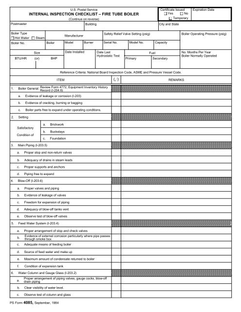
boiler safety valve testing free sample
Boiler explosions have been responsible for widespread damage to companies throughout the years, and that’s why today’s boilers are equipped with safety valves and/or relief valves. Boiler safety valves are designed to prevent excess pressure, which is usually responsible for those devastating explosions. That said, to ensure that boiler safety valves are working properly and providing adequate protection, they must meet regulatory specifications and require ongoing maintenance and periodic testing. Without these precautions, malfunctioning safety valves may fail, resulting in potentially disastrous consequences.
Boiler safety valves are activated by upstream pressure. If the pressure exceeds a defined threshold, the valve activates and automatically releases pressure. Typically used for gas or vapor service, boiler safety valves pop fully open once a pressure threshold is reached and remain open until the boiler pressure reaches a pre-defined, safe lower pressure.
Boiler relief valves serve the same purpose – automatically lowering boiler pressure – but they function a bit differently than safety valves. A relief valve doesn’t open fully when pressure exceeds a defined threshold; instead, it opens gradually when the pressure threshold is exceeded and closes gradually until the lower, safe threshold is reached. Boiler relief valves are typically used for liquid service.
There are also devices known as “safety relief valves” which have the characteristics of both types discussed above. Safety relief valves can be used for either liquid or gas or vapor service.
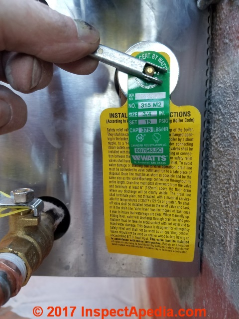
Nameplates must be fastened securely and permanently to the safety valve and remain readable throughout the lifespan of the valve, so durability is key.
The National Board of Boiler and Pressure Vessel Inspectors offers guidance and recommendations on boiler and pressure vessel safety rules and regulations. However, most individual states set forth their own rules and regulations, and while they may be similar across states, it’s important to ensure that your boiler safety valves meet all state and local regulatory requirements.
The National Board published NB-131, Recommended Boiler and Pressure Vessel Safety Legislation, and NB-132, Recommended Administrative Boiler and Pressure Vessel Safety Rules and Regulationsin order to provide guidance and encourage the development of crucial safety laws in jurisdictions that currently have no laws in place for the “proper construction, installation, inspection, operation, maintenance, alterations, and repairs” necessary to protect workers and the public from dangerous boiler and pressure vessel explosions that may occur without these safeguards in place.
The American Society of Mechanical Engineers (ASME) governs the code that establishes guidelines and requirements for safety valves. Note that it’s up to plant personnel to familiarize themselves with the requirements and understand which parts of the code apply to specific parts of the plant’s steam systems.
High steam capacity requirements, physical or economic constraints may make the use of a single safety valve impossible. In these cases, using multiple safety valves on the same system is considered an acceptable practice, provided that proper sizing and installation requirements are met – including an appropriately sized vent pipe that accounts for the total steam venting capacity of all valves when open at the same time.
The lowest rating (MAWP or maximum allowable working pressure) should always be used among all safety devices within a system, including boilers, pressure vessels, and equipment piping systems, to determine the safety valve set pressure.
Avoid isolating safety valves from the system, such as by installing intervening shut-off valves located between the steam component or system and the inlet.
Contact the valve supplier immediately for any safety valve with a broken wire seal, as this indicates that the valve is unsafe for use. Safety valves are sealed and certified in order to prevent tampering that can prevent proper function.
Avoid attaching vent discharge piping directly to a safety valve, which may place unnecessary weight and additional stress on the valve, altering the set pressure.

Safety is of the utmost importance when dealing with pressure relief valves. The valve is designed to limit system pressure, and it is critical that they remain in working order to prevent an explosion. Explosions have caused far too much damage in companies over the years, and though pressurized tanks and vessels are equipped with pressure relief vales to enhance safety, they can fail and result in disaster.
That’s also why knowing the correct way to test the valves is important. Ongoing maintenance and periodic testing of pressurized tanks and vessels and their pressure relief valves keeps them in working order and keep employees and their work environments safe. Pressure relief valves must be in good condition in order to automatically lower tank and vessel pressure; working valves open slowly when the pressure gets high enough to exceed the pressure threshold and then closes slowly until the unit reaches the low, safe threshold. To ensure the pressure relief valve is in good working condition, employees must follow best practices for testing them including:
If you consider testing pressure relief valves a maintenance task, you’ll be more likely to carry out regular testing and ensure the safety of your organization and the longevity of your
It’s important to note, however, that the American Society of Mechanical Engineers (ASME) and National Board Inspection Code (NBIC), as well as state and local jurisdictions, may set requirements for testing frequency. Companies are responsible for checking with these organizations to become familiar with the testing requirements. Consider the following NBIC recommendations on the frequency for testing relief valves:
High-pressure steam boilers greater than 15 psi and less than 400 psi – perform manual check every six months and pressure test annually to verify nameplate set pressure
High-pressure steam boilers 400 psi and greater – pressure test to verify nameplate set pressure every three years or as determined by operating experience as verified by testing history
High-temperature hot water boilers (greater than 160 psi and/or 250 degrees Fahrenheit) – pressure test annually to verify nameplate set pressure. For safety reasons, removal and testing on a test bench is recommended
When testing the pressure relief valve, raise and lower the test lever several times. The lever will come away from the brass stem and allow hot water to come out of the end of the drainpipe. The water should flow through the pipe, and then you should turn down the pressure to stop the leak, replace the lever, and then increase the pressure.
One of the most common problems you can address with regular testing is the buildup of mineral salt, rust, and corrosion. When buildup occurs, the valve will become non-operational; the result can be an explosion. Regular testing helps you discover these issues sooner so you can combat them and keep your boiler and valve functioning properly. If no water flows through the pipe, or if there is a trickle instead of a rush of water, look for debris that is preventing the valve from seating properly. You may be able to operate the test lever a few times to correct the issue. You will need to replace the valve if this test fails.
When testing relief valves, keep in mind that they have two basic functions. First, they will pop off when the pressure exceeds its safety threshold. The valve will pop off and open to exhaust the excess pressure until the tank’s pressure decreases to reach the set minimum pressure. After this blowdown process occurs, the valve should reset and automatically close. One important testing safety measure is to use a pressure indicator with a full-scale range higher than the pop-off pressure.
Thus, you need to be aware of the pop-off pressure point of whatever tank or vessel you test. You always should remain within the pressure limits of the test stand and ensure the test stand is assembled properly and proof pressure tested. Then, take steps to ensure the escaping pressure from the valve is directed away from the operator and that everyone involved in the test uses safety shields and wears safety eye protection.
After discharge – Because pressure relief valves are designed to open automatically to relieve pressure in your system and then close, they may be able to open and close multiple times during normal operation and testing. However, when a valve opens, debris may get into the valve seat and prevent the valve from closing properly. After discharge, check the valve for leakage. If the leakage exceeds the original settings, you need to repair the valve.
According to local jurisdictional requirements – Regulations are in place for various locations and industries that stipulate how long valves may operate before needing to be repair or replaced. State inspectors may require valves to be disassembled, inspected, repaired, and tested every five years, for instance. If you have smaller valves and applications, you can test the valve by lifting the test lever. However, you should do this approximately once a year. It’s important to note that ASME UG136A Section 3 requires valves to have a minimum of 75% operating pressure versus the set pressure of the valve for hand lifting to be performed for these types of tests.
Depending on their service and application– The service and application of a valve affect its lifespan. Valves used for clean service like steam typically last at least 20 years if they are not operated too close to the set point and are part of a preventive maintenance program. Conversely, valves used for services such as acid service, those that are operated too close to the set point, and those exposed to dirt or debris need to be replaced more often.
Pressure relief valves serve a critical role in protecting organizations and employees from explosions. Knowing how and when to test and repair or replace them is essential.

The steam will condenses and partial vacuum occurred and move back the water thealong the pipe with very high velocity, and the water will strike at the vent or valves.
Once being dose into the boiler water floating solid particles and suspended solid are settled tothe bottom of the boiler and easily remove by blowing down.
All safety valves are to be set to operate under steam a little above working pressure not greaterthan 3% above the approve working pressure of the boiler.

Emergency relief valve related phrases on Microchek.com include multi-port relief valve, boiler code safety valve testing, johnson control valves + water well + air conyrol,
directional hydraulic control valve, and sump pump flo control check valve. Microcheks innovative designs use a minimum number of parts to assure reliability through simplicity. The Microchek valve has a low pressure drop and can be specified with a wide variety of cracking pressures. Call us for a FREE check valve sample. 1-800-780-0008 Or fax us at 1-800-622-0002. We can select valves that fall into a specific cracking pressure range if needed.
This valve is the heart of our system and has a great design. We want the opportunity to help you solve your flow control applications and we can build special configurations. We offer competitive pricing and reliability because we are the manufacture. Parts are molded and assembled in the U.S. The Microchek system incorporates this cartridge and a wide selection of end pieces to accommodate most connection requirements. Relief valves are used to hold a fluid circuit or reservoir at a positive or negative pressure. Our staff is available to advise you on your applications. Please ask for a FREE sample that meets your needs.
The Microchek valve is a cartridge check valve incorporating an innovative guided poppet design. The system is available in a variety of polymers and elastomers to ensure compatibility with most liquids and gases. This vaulve may be used alone or as the central component of the system.
Microchek is a company with an expertise in cartridge check valves. Find emergency relief valve on Microchek.com. The Microchek valve incorporates our innovative check valve module with ultrasonically welded end pieces.
If your design requires a unique configuration, we will be pleased to quote your needs. Microcheks innovative designs use a minimum number of parts to assure reliability through simplicity. The system is available in a variety of polymers and elastomers to ensure compatibility with most liquids and gases. The Microchek valve is a cartridge check valve incorporating an innovative guided poppet design. The Microchek valve incorporates our innovative check valve module with ultrasonically welded end pieces. We want the opportunity to help you solve your flow control applications and we can build special configurations.
If your design requires a unique configuration, we will be pleased to quote your needs. The Microchek system incorporates this cartridge and a wide selection of end pieces to accommodate most connection requirements. This vaulve may be used alone or as the central component of the system. Related terms include directional hydraulic control valve, johnson control valves + water well + air conyrol, multi-port relief valve, boiler code safety valve testing, and sump pump flo control check valve. Relief valves are used to hold a fluid circuit or reservoir at a positive or negative pressure.
The Microchek valve has a low pressure drop and can be specified with a wide variety of cracking pressures. We can select valves that fall into a specific cracking pressure range if needed. Our staff is available to advise you on your applications. Please ask for a FREE sample that meets your needs. Call us for a FREE check valve sample. 1-800-780-0008 Or fax us at 1-800-622-0002. We offer competitive pricing and reliability because we are the manufacture. Parts are molded and assembled in the U.S. This valve is the heart of our system and has a great design.
Our staff is available to advise you on your applications. Please ask for a FREE sample that meets your needs. This vaulve may be used alone or as the central component of the system. We can select valves that fall into a specific cracking pressure range if needed.
In order to ensure that the maximum allowable accumulation pressure of any system or apparatus protected by a safety valve is never exceeded, careful consideration of the safety valve’s position in the system has to be made. As there is such a wide range of applications, there is no absolute rule as to where the valve should be positioned and therefore, every application needs to be treated separately.
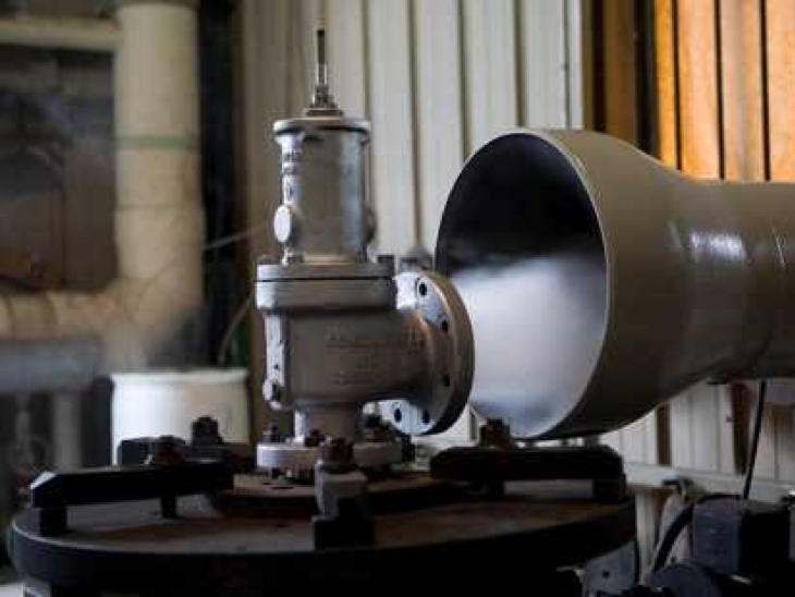
A common steam application for a safety valve is to protect process equipment supplied from a pressure reducing station. Two possible arrangements are shown in Figure 9.3.3.
The safety valve can be fitted within the pressure reducing station itself, that is, before the downstream stop valve, as in Figure 9.3.3 (a), or further downstream, nearer the apparatus as in Figure 9.3.3 (b). Fitting the safety valve before the downstream stop valve has the following advantages:
• The safety valve can be tested in-line by shutting down the downstream stop valve without the chance of downstream apparatus being over pressurised, should the safety valve fail under test.
• When setting the PRV under no-load conditions, the operation of the safety valve can be observed, as this condition is most likely to cause ‘simmer’. If this should occur, the PRV pressure can be adjusted to below the safety valve reseat pressure.
Indeed, a separate safety valve may have to be fitted on the inlet to each downstream piece of apparatus, when the PRV supplies several such pieces of apparatus.
• If supplying one piece of apparatus, which has a MAWP pressure less than the PRV supply pressure, the apparatus must be fitted with a safety valve, preferably close-coupled to its steam inlet connection.
• If a PRV is supplying more than one apparatus and the MAWP of any item is less than the PRV supply pressure, either the PRV station must be fitted with a safety valve set at the lowest possible MAWP of the connected apparatus, or each item of affected apparatus must be fitted with a safety valve.
• The safety valve must be located so that the pressure cannot accumulate in the apparatus viaanother route, for example, from a separate steam line or a bypass line.
It could be argued that every installation deserves special consideration when it comes to safety, but the following applications and situations are a little unusual and worth considering:
• Fire - Any pressure vessel should be protected from overpressure in the event of fire. Although a safety valve mounted for operational protection may also offer protection under fire conditions,such cases require special consideration, which is beyond the scope of this text.
• Exothermic applications - These must be fitted with a safety valve close-coupled to the apparatus steam inlet or the body direct. No alternative applies.
• Safety valves used as warning devices - Sometimes, safety valves are fitted to systems as warning devices. They are not required to relieve fault loads but to warn of pressures increasing above normal working pressures for operational reasons only. In these instances, safety valves are set at the warning pressure and only need to be of minimum size. If there is any danger of systems fitted with such a safety valve exceeding their maximum allowable working pressure, they must be protected by additional safety valves in the usual way.
In order to illustrate the importance of the positioning of a safety valve, consider an automatic pump trap (see Block 14) used to remove condensate from a heating vessel. The automatic pump trap (APT), incorporates a mechanical type pump, which uses the motive force of steam to pump the condensate through the return system. The position of the safety valve will depend on the MAWP of the APT and its required motive inlet pressure.
This arrangement is suitable if the pump-trap motive pressure is less than 1.6 bar g (safety valve set pressure of 2 bar g less 0.3 bar blowdown and a 0.1 bar shut-off margin). Since the MAWP of both the APT and the vessel are greater than the safety valve set pressure, a single safety valve would provide suitable protection for the system.
Here, two separate PRV stations are used each with its own safety valve. If the APT internals failed and steam at 4 bar g passed through the APT and into the vessel, safety valve ‘A’ would relieve this pressure and protect the vessel. Safety valve ‘B’ would not lift as the pressure in the APT is still acceptable and below its set pressure.
It should be noted that safety valve ‘A’ is positioned on the downstream side of the temperature control valve; this is done for both safety and operational reasons:
Operation - There is less chance of safety valve ‘A’ simmering during operation in this position,as the pressure is typically lower after the control valve than before it.
Also, note that if the MAWP of the pump-trap were greater than the pressure upstream of PRV ‘A’, it would be permissible to omit safety valve ‘B’ from the system, but safety valve ‘A’ must be sized to take into account the total fault flow through PRV ‘B’ as well as through PRV ‘A’.
A pharmaceutical factory has twelve jacketed pans on the same production floor, all rated with the same MAWP. Where would the safety valve be positioned?
One solution would be to install a safety valve on the inlet to each pan (Figure 9.3.6). In this instance, each safety valve would have to be sized to pass the entire load, in case the PRV failed open whilst the other eleven pans were shut down.
If additional apparatus with a lower MAWP than the pans (for example, a shell and tube heat exchanger) were to be included in the system, it would be necessary to fit an additional safety valve. This safety valve would be set to an appropriate lower set pressure and sized to pass the fault flow through the temperature control valve (see Figure 9.3.8).
A series of anomalies occurred in the boiler room that evening. The steel compression tank for the hydronic loop flooded, leaving no room for expansion. Water will expand at 3% of its volume when heated from room temperature to 180° F. When the burner fired, the expansion of the water increased the system pressure within the boiler. The malfunctioning operating control did not shut off the burner at the set point which caused the relief valve to open.
The brass relief valve discharge was installed with copper tubing piped solid to a 90° ell on the floor and the tubing further extended to the floor drain. The combination of hot water and steam from the boiler caused the discharge copper tubing to expand, using the relief valve as a fulcrum. The expansion of the copper discharge tubing pressing against the floor was enough to crack the brass relief valve, flooding the boiler room. The damage was not discovered until the next morning, several hours after the leak occurred. Thousands of dollars in damage was sustained and luckily no one was injured.
Each boiler requires some sort of pressure relieving device. They are referred to as either a safety, relief or safety relief valve. While these names are often thought of as interchangeable, there are subtle differences between them. According to the National Board of Boiler and Pressure Vessel Inspectors, the following are the definitions of each:
• Safety valve— This device is typically used for steam or vapor service. It operates automatically with a full-opening pop action and recloses when the pressure drops to a value consistent with the blowdown requirements prescribed by the applicable governing code or standard.
• Relief valve— This device is used for liquid service. It operates automatically by opening farther as the pressure increases beyond the initial opening pressure and recloses when the pressure drops below the opening pressure.
• Safety relief valve— This device includes the operating characteristics of both a safety valve and a relief valve and may be used in either application.
• Temperature and pressure safety relief valve— This device is typically used on potable water heaters. In addition to its pressure-relief function, it also includes a temperature-sensing element which causes the device to open at a predetermined temperature regardless of pressure. The set temperature on these devices is usually 210°.
• Relief valve piping— The boiler contractor installed a bushing on the outlet of the safety relief valve. Instead of 1 1/2-in. pipe, the installer used 3/4-in. pipe. When asked about it, he answered that he did not have any 1 1/2-in. pipe but had plenty of 3/4-in. pipe. I explained and then had to show the disbelieving contractor the code that states that the relief valve discharge piping has to be the same diameter as the relief valve outlet (see 2012 International Mechanical Code, 1006.6). By reducing the discharge pipe size, the relieving capacity of the safety valve may not be adequate to properly relieve the pressure inside the boiler, causing a dangerous situation.
The code also states that the discharge material shall be of rigid pipe that is approved for the temperature of the system. The inlet pipe size shall be full diameter of the pipe inlet for the relief valve. Some manufacturers suggest using black iron pipe rather than copper tubing. If using copper, it should have an air space that allows expansion should the relief valve open to avoid the accident that I referenced above. The discharge piping has to be supported and the weight of the piping should not be on the safety relief valve. Valves are not permitted in the inlet piping to or discharge piping from the relief valve. If you are using copper tubing on discharge piping, verify that there is room for expansion.
• Installation— Read the manufacturer’s installation manual as each may have different requirements. For instance, Conbraco requires that the discharge piping must terminate with a plain end and use a material that can handle temperatures of 375° or greater. This will preclude PVC or CPVC pipe for the discharge piping. The instruction manual for its model 12-14 steam relief valve stipulates that you cannot use a pipe wrench to install it. That would be good to know.
I once visited Boiler Utopia as the floor was clean and waxed. All the pipes were covered and exposed pipes were painted. There were large stickers detailing what was inside each pipe as well as directional arrows. Nothing was stacked next to the boilers. Yellow caution lines were painted on the floor around each boiler. I was in heaven. As I walked around the rear of the boiler, something clicked and triggered a warning bell. The discharge of the relief valve piping was about 6 in. from the floor but instead of a plain or angled cut end, the pipe had a threaded pipe cap on the termination. I asked the maintenance person about it and he said that the valve was leaking all over his newly waxed floor and this was the only way he could stop it. When I said that the discharge pipe should not have been threaded, he explained that it was not threaded and he had to take it to the local hardware store to thread it. I informed him that the cap had to be removed. We cut the pipe on an angle to prevent this.
• Steam boiler— Most manufacturers recommend a drip pan ell on the discharge of the steam boiler relief valve to eliminate the weight of the discharge piping on the relief valve. Some codes require the discharge to be vented outdoors.
• Testing— I will ask the attendees in my classes, “How often do you test the relief valves?” Most do not make eye contact and when I follow up with, “Why are they not tested?” I often hear that opening the relief valve will cause it to leak. I suggest that you refer to each manufacturer’s directions for testing. For instance, one will recommend once a year while another recommends twice a year. One manufacturer says, “Safety/relief valves should be operated only often enough to assure they are in good working order.” I am not sure what that even means. You want to also verify the proper test procedure as some will only want the relief valve tested when the boiler is at 75% of the rated pressure or higher of the relief valve.

A ship’s engine room is a complex arrangement of machinery and systems, which is used in carrying out various operations on board. One such important machinery, which has been assisting ships since the start of shipping, is the marine boiler.
Earlier, marine boilers were primarily installed on a ship for the propulsion plant, which used to run on steam (steam engine). Today, the steam generated by the boiler is utilized in various systems in the engine room, including heating of fuel for the main engine. Considering the importance of marine boilers and the risks involved with its operation on ships, there has been constant development in the industry to enhance boiler safety on board. Some even consider it one of the “deadliest” machinery systems on board.
Boiler Explosion: Many cases of boiler explosion in the past have shown how dangerous marine boiler can be if not operated professionally. Accidents happen when the fuel system within the boiler is mishandled, or when the steam pressure inside the boiler drum is not regulated.
Boiler Fire/ Meltdown: The boiler fire is another type of accident which can destroy all the tubes inside the boiler and lead to an explosion or spreading of fire within the ship.
Hot Surface: The boiler and the associated pipes, valves, and auxiliaries have a very hot surface as they carry steam to different parts of the ship. A direct skin contact with any of the exposed surface will lead to severe burn.
Other Risks: Other risks such as high pressurized parts, handling harmful chemicals, moving machinery etc. are also associated with operating marine boilers.
Needless to say, safety is a critical aspect when operating a high or even a low-pressure boiler on a ship and therefore different marine boiler devices are provided.
Boiler Safety System and Instruments: A modern marine boiler is fitted with several safety devices for the protection of the operator. For easy understanding, let us divide these instruments/devices as per the system they are fitted in –
Steam Safety System: The steam system in the boiler is a high pressure, high-temperature area. To safeguard the operator and the boiler itself, it is fitted with the following safety features:
Pressure gauge: Multiple pressure gauges are fitted to ensure the operator has an idea of the current value of pressure inside the boiler. Usually, two pressure gauges are fitted on the boiler and one line is taken from the steam drum to the engine control room, to display the steam pressure remotely.
The pressure gauges are also incorporated with cut-in and cut-out automation systems, i.e. the input from the pressure gauges are used to operate the boiler burner. When the pressure reaches the set value, the boiler burner will stop firing and when the pressure drops to a lower set value, the burner will be switched ON to raise the boiler pressure.
Safety Valve: Boiler safety valve is an extremely important safety equipment fitted on the steam drum of the boiler. As per SOLAS chapter II-1, every steam boiler and every un-fired steam generator shall be provided with not less than 2 safety valves of adequate capacity. However, with regards to the output or any other feature of a boiler or un-fired steam generator, the administration may permit only one safety valve to be fitted if adequate protection against overpressure is thereby satisfactorily provided.
Usually, an improved high lift is one of the most popular types of safety valves used on a ship. They are set to lift at the blow-off pressure and shut when the pressure reduces to the safe limit. They are set to open at 3 % above working pressure. The lift of valve is one-twelfth of the valve diameter.
Easing Gear: The easing gear is attached to the boiler safety valve. Every individual safety valve is provided with its own easing gear, which is a pulley and wire arrangement (connected to the lever of the safety valve) with an accessible handle at the lower operating boiler platform. It is used to lift the boiler safety valve in case of an emergency (without getting near to the safety valve) and to regularly test the operation of the safety valves.
Boiler Vent: Vent on the boiler drum is required to ensure boiler does not implode once it is shut down. It is normally opened when the pressure gauge shows the reading below 0.5 bars.
Water Safety System: The water system is a high-temperature system and the level and quality of the water inside the water drum plays a crucial role in the safe operation of the boiler. Following are the equipment/system fitted on the water side of the marine boiler:
Low / high water level alarm and cutout: The boiler water drum is fitted with a level sensor, which will continuously monitor the level of water inside the drum. A full drum will carry over the water or will have no space to generate steam, thus reducing the efficiency of the boiler; whereas low or no water level in the drum will lead to over-heating of tubes and can lead to fire or meltdown of the complete boiler.
The low/ high water level provides an early warning to the operator for taking appropriate action to manage the water level inside the boiler water drum.
Too low water level alarm and shut down: The initial warning provided by the above arrangement (low/high water level alarm), may not be sufficient for the operator as there can be a major leak in the tubes, leading to a reduction in the water level. A secondary safety is therefore provided i.e. Too low water level alarm and shut down, which will stop the burner firing to control the overheating of the boiler internal parts.
Water level indicators: The boiler is fitted with multiple water level indicators to make it easy for the operator to see the water drum level and ensure operational safety of the boiler.
Local gauge glasses are provided in a duplex on the boiler drum to ensure at least one gauge glass is operational in case one stops showing the level. Remote water level indicators such as a differential pressure water level sensor, probe level sensor etc. are also provided to indicate the current level in the drum at a remote position such as the engine control room.
Salinity Sensor: The boiler drum is fitted with a salinity sensor, which continuously monitors the dissolved solids content in the water. If the solid (e.g. salt) content exceeds the set value, it trips the boiler to ensure the tubes and boiler internals does not get affected due to the contamination. The operator should either blow down the boiler and feed fresh water to the drum to eliminate the cause which is resulting in high salinity (for e.g. leakage in the condenser)
Fuel Safety System: The boiler is provided with heavy or marine gas fuel oil for generating the heat in the furnace. To ensure the fuel system is operating efficiently, it is fitted with the following boiler safety features:
Low / high fuel oil temperature alarm: Modern marine boilers are meant to operate in different grades of fuel due to the port / ECA regulations for minimizing the air pollution from the ship. The oil temperature is an important factor as it controls the viscosity of the fuel which is directly related to atomization and efficient combustion inside the furnace. If the fuel temperature is not at its set value (which will vary for different grades), the alarm will sound. The operator must stop the alarm and the oil temperature should be brought to normal before restarting the boiler.
Smoke Density alarm: With more stringent rules coming up for environmental protection, the boiler exhaust is fitted with a smoke density sensor which detects the post-combustion product, especially during starting of a boiler and at low loads. If the smoke density is higher than the required value, it will sound an alarm to which the operator needs to check the combustion of the boiler
Operational Safety: Automation, alarms, and warnings have made the life of seafarers on ships a lot easier than what it used to be in terms of boiler safety. However, professional engineers rarely depend on them and always rely on the best practice for efficiently running the machinery.
Efficient hot well/ cascade tank function: Maintaining the correct hot-well temperature will decrease the steam production time of the boiler compared to a low-temperature water supply by the cascade tank
Routine furnace inspection: Boiler furnace is responsible to contain the heat within the boiler and to reduce the surface heat loss. Maintaining the furnace refractory will lead to efficient boiler steam production
Lagging: Once the steam comes out of the boiler via main steam stop valve, it is supplied to several systems via pipes and distribution valves. A proper lagging on the pipes and valves will ensure the boiler need not run extra as the steam loss will be contained. Also, it ensures the safety of ship staff from surface burns.
Maintenance: On-time maintenance such as testing of safety valve, cleaning of boiler tubes etc. will result in safe and efficient working of the marine boiler.


 8613371530291