
boiler safety valve testing frequency in stock

When it comes to understanding pressure relief valve testing requirements, there’s a lot of information out there, but not all of it seems conclusive. If you’re new to pressure relief valves or are getting started in a new industry, it can be tough to decipher what testing requirements your facility needs to meet.
While we can’t provide the specific testing requirements for every industry, we can offer a few general testing requirements, and point you in the right direction to find the information you need for your facility’s unique testing requirements:
It’s good to keep in mind that every industry and region has unique pressure relief valve testing requirements. Your facility may be required to just bench test pressure relief valves every five years, or you may have to test valves every year, but bench test and repair valves every three to five years. There is a large variance in the testing requirements for pressure relief and safety valves depending on your industry and your region. That said, there are a few general testing requirements we can look at to start with.
The National Board Inspection Code, created by the National Board of Boiler and Pressure Valve Inspectors, makes the following recommendations on the frequency of testing for safety and pressure relief valves, depending on the temperature, psi, and function of your boiler:
High-pressure steam boilers greater than 15 psi and less than 400 psi should be manually checked every 6 months and pressure tested annually to verify nameplate set pressure.
High-pressure steam boilers greater than 400 psi should be pressure tested to verify nameplate set pressure every three years, or as determined by operating experience as verified by testing history.
High-temperature hot water boilers operating at greater than 160 psi and/or 250° F should be pressure tested annually to verify nameplate set pressure.
It’s important to remember that these are general pressure valve testing recommendations. For specific requirements, you’ll have to verify your unique jurisdictional and industry code requirements. See the resources below for more information.
The National Board Inspection Code is an industry-recognized name offering quality information on pressure relief valve testing requirements. Here, you’ll find a wealth of information and testing best practices.
The ASME is another organization setting pressure relief valve testing requirements, and offering the necessary training engineers need to test and understand the testing procedures for pressure relief valves. In addition to testing requirements and standards, the ASME offers a variety of online courses on pressure relief valves, from fabrication and proper installation to inspection and repair.
For specific testing standards, it’s best to check with your industry and your regional jurisdiction. Pressure relief valve testing requirements can vary by state or region and are most often industry-specific. Check your industry’s standards, and check local code requirements to ensure your facility is adhering to the most relevant pressure relief valve testing requirements.
When you’re looking for the pressure relief valve testing requirements relevant to your facility, it’s important to understand the different testing methods that are available to you. It’s likely that regardless of your industry if you have safety and pressure relief valves in use at your facility, you’ll have to bench test those valves at least every five years.
In addition to those bench tests, though, you’ll also have to perform manual or on-site pressure relief valve testing. Here’s a quick look at the three most common pressure relief valve testing methods you’ll see when researching pressure relief valve testing requirements:
The most commonly mandated form of pressure relief valve testing, bench testing is unique in that it requires you completely shut down your facility’s system and remove all pressure relief valves. The valves are then transported to a lab where they are tested and repaired as necessary. Tested valves are then re-installed in your system.
Bench testing is the most involved method of pressure relief valve testing, but as this is how valves are tested when they’re manufactured, the industry considers this to be the most thorough testing method.
Inline testing is another accurate pressure relief valve testing method that doesn’t require the removal of valves or facility downtime. With inline safety relief valve testing equipment, a trained technician can test valves in the system to calculate the real setpoint of a valve in the system.
While inline testing cannot take the place of mandated bench testing, it is a more efficient form of testing for other regular testing requirements. Inline pressure relief valve testing is the ideal choice for any required testing that does not have to be bench testing, as it eliminates the need for downtime while still providing exceptionally accurate results.
Some pressure relief valve testing requirements will call for regular manual testing for freedom of operation. This is a basic test that can be done on-site. To complete an operated-in-place test, the test lever on the valve is manually activated. This test functions to ensure that the valve can open and shut tightly, but it does not verify at what pressure the valve opens and shuts. This is a test that may be required quarterly or bi-annually, to ensure the most basic functionality of safety relief valves.
Pressure relief valve testing is necessary for any facility with safety relief and pressure relief valves. For more information about the equipment you need for pressure relief valve testing, the profitability of certain testing methods, and more, head to the AccuTEST blog. There, you’ll find a variety of resources on everything from implementing inline safety relief valve testing to minimizing plant downtime.
If your company requires regular pressure relief valve testing, you might be interested in AccuTEST’s high-tech equipment. Offering inline testing with accurate, repeatable results, our system is the best on the market. See how our equipment works in real-time — schedule a live webinar demo today.
A relief valve is one of the most crucial pressured system components and often the last device to prevent catastrophic failures in high-pressured systems. That is why it is essential that relief valves are always certified and should work at all times.
Relief valves are pressure valves that are designed to open at a preset pressure and discharge fluid until the pressure drops to a safe and acceptable level. This means the relief valve is the last resort that releases pressure when other components in the system have failed to control the pressure.
Safety is of paramount importance when it comes to dealing with relief valves. So, it’s critical for industries to make sure the valves are working as designed.
The only way to do that is through periodic inspection and standardized testing. The standards about relief valves and associated assemblies like boilers and pressured vessels are regulated by ASME, API, OSHA, National Board, and individual State codes.
Standard requirements include periodic inspection, testing, and recertification. Certification assures that a valve’s condition and performance are essentially equal to that of a new valve.
Though ASME is the leading organization governing pressured systems’ standards and codes, the body itself does not certify the valves. Certification and recertification of relief valves are done by the National Board (NB).
Performing periodic testing on relief valves is the best practice to ensure that the valves are in good working condition and the employees and work environment is safe.
The above recommendations constitute correct inspecting and testing practices for efficient Relief Valve operations and, ultimately, a safe working environment. However, one crucial safety measure is to use a pressure indicator with a full-scale range higher than the valve’s relief pressure.
In fact, we believe proper valve inspection, testing, and maintenance is the best investment you make in the safety and security of your company and employees.
Our valve experts focus on getting your old valves tested and recertified for safe use. On top of that, we evaluate the repair condition of every valve and recommend the right solution to manage your equipment better.

When I teach my steam classes, I ask the attendees, "Do you test the pop safety valve?" Most do not. When I ask why, they tell me the same reason; the safety valve will leak. I joke during the classes that you do not want to test the pop safety valve on a Friday afternoon because it will almost certainly leak. I then ask, Do you check the low water cutoff? They look at me like I have a third eye and say they always check the low water cutoff. If you test the low water cutoff, you should test the pop safety valve. It is the last line of defense against a potential catastrophe. One of the things I do when performing a boiler service call is to explain the duty of the pop safety valve and ask the customer if they would like to have it tested. I explain that it could leak and if they refuse to test it, I will notate it on my service call in case something happens. In this way, my company is protected.
The best way to understand the pop safety valve is to read the instructions which came with the valve. I don"t have a life, and while you are watching the Masked Singer, I read O & M manuals. I know, I"m weird. I figure it"s my job to share things I find while reading these page-turners. The manufacturer hides all sorts of useful tidbits on the installation and maintenance of their valve. I have enclosed some information I gleaned while reading the instructions for a Conbraco/Apollo pop safety valve.
The valve must be mounted in a vertical, upright position directly to a clean, tapped opening in the top of the boiler. I see many safety valves installed horizontally and wonder if that voids the warranty. There should be no restrictions or valves in the piping to or from the safety valve. The installation instructions require the discharge piping to be schedule 40 pipe. They specifically say not to use schedule 80 pipe, which is 50% thicker than schedule 40 pipe. Many installers use copper tubing for the discharge, which does not meet the instructions. The other thing which confuses me the manufacturer instructs you not to use a pipe wrench to install the safety valve. I would wager 99% of all valves are installed using a pipe wrench. I wonder what kind of valve they want you to use.
I consult the pop safety manufacturer or the building insurance company to determine the frequency of tests. Apollo recommends quarterly testing using the Try Lever Test unless the valve is located in a severe service condition, and then it should be done more often. They further state the pop safety valve should have a Pressure Test annually before the heating season or at the end of any non-service period. This test will check your courage as you have to jump out the pressure controls and watch the operation of the boiler as the pressure builds. If the pop safety valve opens at the set pressure, the valve is working properly. This is not a test a novice should do alone.
Apollo suggests checking the pop safety valve at or near the maximum operating pressure by holding the test lever fully open for at least 5 seconds and letting it pop closed. On a low-pressure steam system, the pop safety valve is set for 15 psi. I like to run the boiler steam pressure up to 12 psi or higher to check the pop safety valve. After the test, I drop it to the operating pressure the owner requires. If the valve does not open, the boiler should be shut down until it is checked by a licensed contractor or qualified service person.
The pop safety manufacturer requires a minimum pressure differential of five psi between the pressure relief valve set pressure and the boiler operating pressure. It further states, Under no circumstances should the margin be less than five psig. On a low-pressure steam boiler, the pop safety valve will be set for 15 psi. That means the boiler steam pressure should be ten psi or lower. In breweries, it is common to see the boiler pressure set at 12-14 psi. This is less than the five psi differential and could create a dangerous condition.

A: Maintenance should be performed on a regular basis. An initial inspection interval of no longer than 12 months is recommended. The user must establish an appropriate inspection interval depending on the service conditions, the condition of the valve and the level of performance desired.
The ASME Boiler and Pressure Vessel Code does not require nor address testing installed valves. The only thing the code states are design and installation requirements, such as some valves must have a lifting lever. For instance for Section VIII:
“Each pressure relief valve on air, water over 140° F, or steam service shall have a substantial lifting device which when activated will release the seating force on the disk when the pressure relief valve is subjected to a pressure of at least 75% of the set pressure of the valve.”
A: This drain hole is required on some models by the ASME Boiler and Pressure Vessel Code. It is intended to prevent any condensate from accumulating in the body that may freeze or corrode internal valve parts and prevent the valve from opening. The drain hole should be piped away to safely dispose of any discharge or condensate.
A: This is often a confusing topic. The correct installation often looks backwards from what appears to be correct. A paper instruction tag illustrating the proper connection is attached to each valve. Vacuum valves should have the NPT threads that are cast integral to the body attached to the vacuum source. See the assembly drawing for additional clarification.
A: Typically, the valve should be nameplate set to open at the MAWP (Maximum Allowable Working Pressure) of the vessel the valve is intended to protect. There is a tolerance to actual set pressure, which means a valve set at 100 psig nameplate may open slightly above or below 100 psig. Consult the current ASME Boiler and Pressure Vessel Code for tolerance classes and special situations when the set pressure may be different than the MAWP.
A: It is normal for spring-operated safety valves to exhibit leakage or simmer/warn, as the system operating pressure approaches the nameplate set pressure, typically in the 80%-90% range of nameplate set pressure. The ASME Boiler and Pressure Vessel Code does not require a specific seat tightness requirement. A certain level of leakage is allowed per manufacturers’ literature and API-527 Seat Tightness Performance Standards, both of which can be found in the Technical Reference Catalog and in the Data Supplement, summarized as follows:
API-527 Standard Seat Tightness Performance: A Functional Test Report (FTR) is automatically provided for valves ordered to API-527. See API 527 for complete details.
A: Maintain a minimum operating gap of 10% between the system operating pressure and the safety valve’s nameplate set pressure. Since direct spring-operated safety valves may “simmer” or “warn” at 90% of the nameplate set pressure, and since the factory standard leak test is performed at 80% of nameplate set pressure, better seat tightness performance can be expected with an operating gap of 20%.
Variance of set pressure is allowed, i.e., a Section VIII air valve with a nameplate of 100 psig set pressure may open from 97 psig to 103 psig, but will be factory set around 102 psig.
Gage issues may lead to incorrect reporting of set pressure. Ensure the gage is within calibration and is accurate for the pressure being measured. Rapid increases in system pressure (more than 2 psig/second, water hammer, reciprocating pumps) can make the valve appear to be opening early because the gage cannot accurately report the pressure to which the valve is exposed.
A: Yes. Section I valves have more stringent setting blowdown requirements and may be used in Section VIII steam applications since they meet all the requirements as specified in Section VIII UG-125(a) “Pressure Relief Devices,” which states pressure relief devices must be “in accordance with the requirements of UG-125 through UG-137.” In addition, UG-125(b) actually specifies that even unfired steam boilers MUST use a Section I pressure relief device.
A: Section VIII UG-136(a)(3) states, “Each pressure relief valve on air, water over 140° F (60° C), or steam service shall have a substantial lifting device which when activated will release the seating force on the disk when the pressure relief valve is subjected to a pressure of at least 75% of the set pressure of the valve.”
The user has a documented procedure and an associated implementation program for the periodic removal of the pressure relief valves for inspection and testing, and repair as necessary.
A: Back pressure reduces set pressure on a one-to-one basis, i.e., a valve set at 100 psig subjected to a backpressure at the outlet of 10 psig will not actuate until system pressure reaches 110 psig. Back pressure drastically reduces capacity; typically backpressure of 10% of set pressure will decrease capacity by 50%. Specific capacity reduction should be determined by the user on a case-by-case basis by flow testing. Back pressure in excess of 10% of set pressure is not recommended.
A: The ASME Boiler and Pressure Vessel Code does not have blowdown requirements for Section VIII (or non-code) valves. Blowdown may vary from less than 2% to more than 50%, depending on many factors including: valve design, dimensional tolerance variation, where the set pressure falls in the set pressure range of a spring, spring rate/force ratio, warn ring/guide settings, etc. Typical blowdown for most valves is 15% to 30%, but cannot be guaranteed. VM
Jim Knox is president, Allied Valve, Inc. (www.alliedvalve.com), a valve repair service company and supplier of Tyco Kunkle and Dresser Consolidated safety valves in the Midwest. Reach him at knoxj@alliedvalveinc.com.
ValvTechnologies and Severn Glocon have reached a partnership agreement that will see collaboration between two of the world’s leading engineering and manufacturing companies specializing in innovative, high-end, severe-service valves.
This article outlines the challenges of lifting large valve assemblies weighing several tons and illustrates the industrial rigging equipment and lifting operations typically used for these valves.

Safety valves are used in a variety of applications, including air/gas, vapor, steam and liquid service. Quadco has been approved by the National Board of Boiler and Pressure Vessel Inspectors to perform safety and relief valve testing, repair and certification.
Our valve experts will focus on getting your valves tested, repaired and calibrated to the required specifications in a timely manner. We evaluate the current condition of every valve and will recommend the right solution to manage your maintenance program.
National Board of Boiler and Pressure Vessel Inspectors certified shop with a steam boiler available for testing and certifying your valves to reduce your downtime.
Quadco uses portable Accutest and Hydraulic equipment to verify the set pressure of in-line safety and safety relief valves without having to shut down a system or unit. By applying force to the valve spindle, coupled with system pressure, and a “true” effective area, specifications are acquired, processed, stored, and printed.

Tired of keeping track of your valve inventory’s annual certification records? We offer complete management of your safety relief valves. With an inventory of repair parts and in stock relief valves of all sizes, we can respond to any customer emergency. We offer annual certification services as well as repair of all major brands, including Kunkle, Conbraco, Consolidated, Dresser, Apollo and more.

Safety valves are used in a variety of applications, including air/gas, vapor, steam and liquid service. Flotech has been approved by the National Board of Boiler and Pressure Vessel Inspectors to perform safety and relief valve testing, repair and certification.
Our valve experts will focus on getting your valves tested, repaired and quickly set to the exact specifications. We evaluate the repair condition of every valve and will recommend the right solution to manage your maintenance program.
Pressure vessels and piping (pressure Pressure 5 yearsb relief valves in combination with rupture disks)
Note 1: If required for personnel or equipment safety, pressure relief devices with eitherthe ASME or National Board of Boiler and Pressure Vessel Inspectors (V or VR) stamp are tobe used.
Note 2: Manual tests are the responsibility of the equipment owner. If a valve is found tobe stuck during manual testing, it must be reported immediately to the ESH Coordinatorand must be subjected to pressure testing. Stuck valves are a serious condition indicatingproblems that must be corrected before operation is continued. Pressure tests areperformed by qualified inspectors or at qualified test facilities. Stamped valve repairs mustbe made by VR Qualified/Certified repair facilities.Note 3: Inspection intervals must be shortened if inspections discover defective ordamaged components. At the discretion of the inspector, the interval may be extended,dependant of service (i.e., inert gas vs. corrosive gas), using the considerations listed insection 2.5.8 (g) of NBIC NB-23 Part 2.Safety relief valves protecting life and property
Generally speaking, safety relief valves have been around since the 1600s in more or less the same design concept.In its primary function, the pressure safety relief valve serves to protect life and property. Acting as a "last resort", thisfully mechanical valve is designed to open based on an over pressure situation within a process pressure system,thus not only protecting life but safeguarding the investment and plant itself.This article reviews the principles of pressure safety relief valves for spring loaded and pilot operated designs. It willcover the applicable European and American codes and standards as well as end user procedures that are keyelements in establishing safety and safe selection. Testing (set pressure verification) and maintenance - importantcriteria once the safety valve has been installed and commissioned - will also be addressed.Pressure safety relief valves should be taken very seriously. Manufactured from castings they may not look verysophisticated, but in their design, accuracy and function they resemble a delicate instrument whilst performing anessential role. Self-contained and self-operating devices, they respond to system conditions and prevent catastrophicfailure when other instruments and control systems fail to adequately control process limits.
It is usually supposed that the Frenchman Papin was the inventor of the safety valve, which he first applied about1682 to his digesterThe safety valve was kept closed by means of a lever and movable weight; sliding the weight along the lever enabledPapin to keep the valve in place and regulate the steam-pressure. It appears now that Papin was only the inventor ofthe improvements just mentioned and that safety valves were already being used some fifty years before by theGerman Glauber (who contributed many valuable additions to the mechanical department of chemistry). In hispractise on philosophical furnaces, translated into English in 1651, he describes the modes by which he preventsretorts and stills from bursting from an excessive pressure. A conical valve was fitted, being ground air-tight to itsseat, and loaded with a "cap of lead", so that when the vapour became too "high" it slightly raised the valve and aportion escaped; the valve then closed again on itself, "being pressed down by the loaded cap and so kept close".The idea was followed up by others and we find in the art of distillation, by John French, published soon afterward inLondon, the following concerning the action of such safety-valves: "Upon the top of a stubble (valve) there may befastened some lead, that if the spirit be too strong, it will only heave up the stubble and let it fall down". It should berealised that the word steam was unknown at the time, being of later coinage. In its place we find in every old bookthe words vapour, spirit, smoke, Ayr and even ghost, whence the modern word gas, for aeriform bodies, is doubtlessderivedIn the New England region of the USA, there were 1700 boiler explosions resulting in 1300 deaths during the fiveyears between 1905 and 1911.The American Society of Mechanical Engineers was asked to formulate a design code. The boiler & pressure vesselcommittee was formed and hence the A.S.M.E. Section 1 for fired vessels was formulated and became a mandatoryrequirement for all States, which recognised the need for regulation. The sole purpose of a pressure-relieving device(safety relief valve) is to protect LIFE and PROPERTY.With the expansion of process industries the need for a code for unfired pressure vessels was identified which gaverise to A.S.M.E. Section VIII.The ASME Codes are mandatory in the USA and Canada. API recommended practices and standards have been animportant guidance for users and engineering companies. In many European countries, national ruIes for theprotection against overpressure of process equipment were developed and remained in force well into the 20thcentury.However, in order to allow free circulation of goods in the European Community, Member States were prohibited frommaking new technical rules and from updating the existing ones. They have to conform to a new directive, thepressure equipment directive PED which was published in 1997. lt has become compulsory for equipment "put in themarket" after 29/05/2002 (refer to Art.20 - par 3 of the PED).Today, the term safety valve should be used to describe - Safety, Safety/Relief and Relief Valves; this term is nowused in European Norms (EN) and ISO 4126 descriptions. Safety valves are included as "Safety Accessories in thePED (Art. 1 par 2.1.3) and are classified in risk category IV (the highest). The manufacturer, in order to EC mark hisproduct must undergo, for each product, a conformity assessment comprising the EC type or design examination andthe assurance of the production quality system. The procedures to certify the conformity to the PED are carried out bya body notified by the Member States of the European Community.With the completion of the above, the manufacturer may stamp the EC mark on his product.
Harmonised standards for safety valvesNo standard is yet harmonised. A list of standards relative to safety valves (and rupture discs), which are in theprocess of being harmonised is given in Table 1. It is not compulsory to follow harmonised standards, but if amanufacturer conforms to these standards, he is presumed to conform to the PED (Art 5 of PED Presumption ofconformity). Otherwise the manufacturer himself must prove that his products conform to the PED.As a consequence of the "New Approach" there have been many changes regarding safety valves, the moresignificant of which being:
When the back pressure exceeds 25% of the full lift pressure, the manufacturer must obtain valve dischargecoefficients after tests carried out in actual backpressure conditions. Reference: par 7.1.2, 7.3.3.4 and 9.1 of prENISO 4126-1 (see Table 1).
PrEN ISO Safety devices for the protection against excessive pressure - Part 3: Safety valves and bursting disc4126-3 safety devices in combination
PrEN ISO D Safety devices for the protection against excessive pressure - Part 5: Controlled safety pressure4126-5 relief systems (CSPRS)
PrEN ISO Safety devices for the protection against excessive pressure - Part 6: Application, selection and4126-6 installation of bursting disc safety devices
If the bellows break, the valve must still open within 10% of the maximum allowable pressure of the equipment beingprotected. Reference: par 5.1.8 of prEN ISO 4126-1. If the valve is set at or close to the design pressure of theprotected vessel (as in the case of 99% of the applications) a way to meet with requirements is to install a balancingpiston to back up the bellows.
It will be possible to install pilot operated valves in some Member States (i.e. the Netherlands and Germany) wherelocal authorities have not approved pilot operated valves up to now. Reference: prEN ISO 4126-4.
Safety valve - steam applications, characterised by rapid, full opening or "pop" action. Relief valve - liquid applications, the valves open in proportion to the increase of system pressure over the opening pressure. Safety/relief valve - pressure relieving device suitable for use as a safety valve or a relief valve depending on its application. Pilot-operated safety valve - in one such valve the spring provides +/-75% of the disk loading; the gas or vapour supplies the remainder through the pilot valve. When the pressure in the vessel reaches the set pressure, the pilot valve relieves the gas pressure (which contributes to the disk loading) to the atmosphere causing the safety valve to open wide. Both the pilot and the main valve contain flexible membranes and, consequently, are limited to the design factors of the membranes. These can be snap acting or modulating and are non-flowing. Conventional safety valve - a conventional safety relief valve is a pressure relief valve characterised by rapid opening or pop action, or by opening in proportion to the increase in pressure over the opening, depending on the application. Such valves may be used either for liquid or compressible fluids. Balanced safety valve - A balanced safety relief valve is a pressure relief valve, which incorporates a means of minimising the effect of backpressure on the operational characteristics (opening pressure, closing pressure, and relieving capacity). Full nozzle - inlet flow passage; only the nozzle and disc insert are in contact with the process media when valve is in the closed position. Semi nozzle - the nozzle, disc insert and part of the valve body are in contact with the process media. Effective discharge area - the nominal orifice size listed in API-526, usually defined by a letter (D thru T) Actual discharge area - the measured minimum net area, which determines the flow through a valve. Coefficient of discharge - ratio of the measured relieving capacity to the theoretical relieving capacity. Simmer - audible or visual escape of fluid between the seat and disc. Applies to valves on compressible fluids, at around 98% of the set pressure. Huddling chamber - annular pressure chamber located beyond the valve seat, this generates the pop characteristics.
M.A.W.P. (Maximum Allowable Working Pressure) - maximum gauge pressure permissible at the top of a completed vessel for a designated temperature. Operating pressure - working pressure in a pipe or vessel. ·Set pressure - pressure at which a relieving device opens and relieves. Operating gap - difference between set pressure of the valve and the operating pressure of the vessel or system. Overpressure - increase over set pressure of a relief device. Accumulation - increase over M.A.W.P. Blowdown - difference between set pressure and re-seating pressure of a safety valve. Back pressure - pressure existing at the outlet of the pressure relieving device. Back pressure is either - constant or variable. Built-up pressure - the pressure existing at the outlet of a pressure relief device caused by the flow through that particular device into a discharge system. Superimposed - the static pressure existing at the outlet of a pressure relief device at the time the device is required to operate. It is the result of pressure in the discharge system from other sources.
Because of their critical safety function, pressure relief valve design rules are very strict. Public safety laws in manycountries require special inspection and verification of compliance with codes before allowing operation of theinstalled equipment.The most widely used and recognised of these codes is the ASME Boiler and Pressure Vessel Code. One of the keyfeatures of the ASME Code is the rule for overpressure protection. These rules provide for the accreditation ofmanufacturers and the certification of pressure relief valves by tests in approved laboratories. Thus, the specificationof ASME Code symbol stamped pressure relief valves assures the end-user that the performance requirementsdefined in the Code has been verified.ISO 4126 provides for design and performance standards, but no accreditation process is in place to ensurecompliance. Other standards groups such as NEN (Europe) provide alliterative specification and control rules. Thebalance of this article, however, focuses on the rules of the ASME Code as it relates to pressure relief valves. Alsoreviewed are contents of certain American Petroleum Institute (API) Standards and Recommended Practices, whichare commonly applied in the petroleum and petrochemical industry.For safety valves, then, the general design codes are the American Society of Mechanical Engineers (ASME) and theAmerican Petroleum Institute (API)
ASME Section I (V) which covers Fired Pressure Vessels (Power Boilers) ASME Section VIII (UV) which covers Process Installations (Unfired Pressure Vessels)
API RP520 Part I. This design manual is widely used for sizing & selection of relief valves. API RP520 Part II. This includes methods of installation. API RP521. Guide for pressure relief and de-pressurising systems. API 526. Flanged steel safety/relief valves for use in the petroleum industry. Gives industry standards for dimensions, pressure-temperature rating, and maximum set pressure and body materials. API RP527. Commercial seat tightness of safety/relief valves with metal to metal & soft seats.
The important sections of the ASME Code which deal with pressure relief valves are Section I {Power Boilers};Section 11 {Materials}; Section 111 {Nuclear}; Section IV {Heating Boilers}; Section VIII {Unfired Pressure Vessels};and Section IX {Welding}.As the applications of interest to the petroleum and chemical industries are primarily covered in ASME Code SectionsI and VIII, only the requirements of these sections are reviewed. AII manufacturers certified to these sections of thecode also comply with materials and welding requirements as they may apply to pressure relief valves. Because ofthe specialised nature of power boilers, the operating characteristics of pressure relief valves are very strict. Springoperated valves are generally required under Section I of the ASME Code.
Pressure relief valves are designed to open automatically at a pre-determined set pressure level of system pressureand to achieve a rated relieving capacity at a specified pressure and temperature above the set point (overpressure)before re-closing at a pressure below the opening point (blowdown). Many manufacturers provide special trim optionsfor liquid service valves because of the properties of incompressible fluids.The simplest and most reliable type of pressure relief valve even to this day some four hundred years on from the firstdesign is the spring-loaded design (Fig. 1) where a spring force opposes the system pressure acting on the valvedisc. When the system pressure rises above the level of the spring force, the valve opens. This valve type may alsobe fitted with a bellows, for better emission control performance (Fig 2).Fig. 1 Spring-loaded pressure relief valve. Fig. 2 Spring-loaded relief valve fitted with a bellows and a balanced piston.
The significant elements of all spring-loaded pressure relief designs are the springs and the seats.The springs must provide the desired compression rate and a reasonable range of adjustment. They must also fit intothe valve bonnet and stay within the design perimeters.The seats may be flat or angled, metal or soft. As the seat area usually defines the load transmitted to and from thespring, very high precision is essential to ensure proper valve operation.
A second type of valve, which is more sophisticated and offers operating advantages in selected applications is thepilot operated pressure relief valve (Fig. 3) Fig. 3 Pilot operated pressure relief valve
This type of valve consists of a main valve and a pilot valve. The pilot responds directly to system pressure andcommunicates with the main valve. As with the spring loaded valve, many unique models exist. However, somecommon design features of pilot operated pressure relief valves include: the sensing line, the pilot valve and the mainvalve.The sensing line is either connected to the valve inlet or a remote location and conveys system pressure to the pilot.The pilot valves senses and responds to the system pressure. The pilot is the controlling member of the valve systemand determines all of the operating characteristics of the valve. It consists of many small parts and passages andusually relies on elastomer seals for operation.The main valve operates in response to the pilot and provides the main rated flow capacity to reduce excesspressure.
The American Petroleum Institute has developed the most commonly applied standards and recommended practicesfor the petroleum and chemical industries in addition to the ASME Code. API Recommended Practice 521 providesexcellent guidance for evaluating causes of overpressure and pressure relief systems.API Recommended Practice 520 Part I is the design manual which is most widely used for the design. sizing andselection of components for pressure relief systems. Part II includes guidelines for recommended piping practicesand methods for determining the reactive force created during valve discharge. If not properly evaluated, thesereactive forces can cause chattering when conventional piping designs are applied. These high performance liquidservice designs ensure smooth, stable operation and full relieving capacity on liquid service.API also provides handling and storage recommendations. API Recommended Practice 526 provides an industrystandard to manufacturers of flanged pressure relief valves and includes a common set of installation dimensions,pressure and temperature ratings, set pressure limits, capacities, and materials. This set of industry standardsensures that valves from different manufacturers will be interchangeable functionally and dimensionally. As manyvalves may not comply with this standard, these variables should be verified before substituting one model foranother.API Recommended Practice 527 provides a basis for testing and acceptance for set pressure and seats tightness ofpressure relief valves.
As pressure relief valves contain neither instrumentation nor external operators it is necessary to establish aneffective program for inspection and maintenance to ensure that they will operate when called upon in emergencysituations.A number of guidelines exist for recommending the basic structure of an effective pressure relief valve inspection andmaintenance program. API Recommended Practice 510 is the Pressure Vessel Inspection Code. Also, the API Guidefor Inspection of Refinery Equipment, Chapter XVI, provides excellent guidance for review of relief valves to ensureoperational readiness.The best policy for assurance of safety is also the best policy for economic considerations. The risk associated withthe lack of attention to suspect pressure relief devices cannot be tolerated and is a major threat to both life and plantavailability.When purchasing new valves, always make certain that you are dealing with a reputable and reliabledistributor/manufacturer. Verify that your vendor has current authorisation to sell advise/manufacture or assemble theproducts that you purchase.
Safety relief valve testing is one of the most important elements of an effective maintenance program. There aremany techniques available for conducting pressure relief valve tests. Obviously, the most desirable type of test is onethat subjects the pressure relief valves to the full operating conditions that it is expected to endure. Such a test hasthe advantage of assuring that all of the operating characteristics of the valve, set pressure, lift and blowdown areacceptable. However, this type of test is often impractical if not impossible.The most practical valve test is usually the bench-testing alternative because a controlled environment can becreated. By transporting valves to a central shop, consistency of test techniques and record keeping of test data canbe monitored. Reference to the manufacturer"s instructions for testing and adjustment is an essential part of anytesting program. These documents are most easily accessed in a shop environment.There are many contract services that provide pressure relief valve testing capabilities. It is important to review andqualify these service contractors in the same manner that valve suppliers are reviewed. The best choice is themanufacturer directly. If this option is impractical then the manufacturer"s authorised service centre would berecommended. Many manufacturers offer training programs to qualify plant maintenance personnel for testing andrepair of pressure relief valves.Note that operator techniques on test benches can influence results! Therefore proper training and qualification ofoperators is a must for consistent and reliable test results.
In the event that a valve is in need of repair, only personnel who have been trained in the appropriate repairtechniques should conduct repairs. In addition, a full reference manual of manufacturer"s instructions should beaccessible.Usually, the manufacturer"s instruction manual will provide limits for inspection and rework of this critical part. Theseat step, seat diameters and disc holder bearing surfaces are of particular interest.Re-machining of control rings is not recommended. If damaged, they should be replaced.The points listed above are also applicable to pilot operated valves. In addition, all elastomers should be replaced aspart of any disassembly.Records should be kept of the "as found" adjustment of adjusting bolt and adjusting rings. This allows for resetting ofadjustable members after overhaul prior to final testing.Valves should be reassembled in the reverse order of disassembly. After reassembly of restored components, finaltesting and adjustment must be completed. Depending upon the test apparatus employed, final ring adjustments maynot be made until after the set pressure has been determined. lf a low volume test stand is used, a "bench setting"will be employed for pressure adjustment. The rings may then be replaced in the "as found" position. AII finaladjustments must be sealed. Seals should be traceable and assigned only to qualified personnel.
Records should be kept which provide equipment history. This is helpful for establishing a proper inspection intervalas well as evaluating the suitability of the equipment employed for the application.Valves requiring major repair should have their inspection interval shortened. Those in excellent condition may havetheir interval lengthened until the optimum balance of economic and safety concerns has been established. Theserecords are a basis for compliance with all safety concerns.

Our repair service center is designed to keep your customer’s safety and relief valves at peak operating efficiency. And put extra profits in your pocket.
North American’s Service Center is equipped to handle any safety valve repair. NASVI has the specifications for nearly every safety valve ever made—allowing technicians to make repairs to exact specifications. The center has six lathes on site, so technicians can restore tolerances on existing parts in quick order. If a part cannot be restored, it can generally be replaced from our extensive parts inventory.
Once repairs are complete, valves are tested and then set at one of six, fully equipped test stations. The boiler is on every day for testing steam valves. It’s always ready, allowing us to set and ship your valves fast.
Over the years, our Service Center has proven popular with maintenance managers. It allows the plant to have their valves repaired, serviced and set quickly, which minimizes downtime. They also like the service because it saves them money.
Our repair service also includes updating the valve to the latest design standard when necessary. All valves serviced in our repair facility carry a one-year standard warranty. North American holds ASME’s V and UV stamps and National Board’s NB and VR stamps. The next time your customer has questions about repairing or upgrading their safety or relief valves, give one of our application engineers a call.
You don’t have to be an expert in the field of safety and relief valves to sell them. We are here to help. Our goal is to make it easy for you to profit from the sales of safety and relief valves. Our expertise comes from taking care of our customers for over 42 years. And our large inventory allows us to offer same day shipment from stock on every valve Kunkle makes.
The sole responsibility of our dedicated applications engineers is to take care of your requirements. We will help you with sales planning, product selection and after sale service when needed. We will even provide you with catalogs that have no reference to NASVI. Our valuable advice is free and as close as your phone. So the next time your customer calls and needs a safety or relief valve, call a NASVI Applications Engineer.
They’ll have a quick answer on price, availability and shipment. When it comes to selling safety valves, you don’t have to stock anything. Simply call 1-800-800-8882 or visit us on the web at www.nasvi.com. We’ll make it easy for you!
Our two-truck unit responds to customer requests anywhere, offering on-site repair and resetting of safety valves during scheduled maintenance shutdowns.
Step into the mobile repair unit and you’ll find all the equipment necessary to perform highest-caliber repairs: sand blaster, compressor, lathe, mill/drill press, lapping machine–-it’s all inside. There’s also a Consolidated® seat-resurfacing machine with all adapters for every orifice in the Maxi-Flow® boiler line. Completed valve work will carry the VR stamp.
The Field Service Unit also includes a state of-the-art computerized lift-assist testing unit that allows for testing set pressures and resetting high-pressure safety valves in the field. The testing unit makes testing valves that are welded in-line or stationary possible without removing the valves. Your customers won’t be required to pressure down or increase pressure to test for set pressure. The lift assist testing unit also allows for resetting valves after repairs have been made while the valves are on-line.
If you have prospects or customers that bought their replacement valves elsewhere because you haven’t been able to provide on-site service, you will want to get back with them and talk about this service. If you have questions about pricing and scheduling of our Field Service Unit, give us a call at (800) 800-8882.
As soon as mankind was able to boil water to create steam, the necessity of the safety device became evident. As long as 2000 years ago, the Chinese were using cauldrons with hinged lids to allow (relatively) safer production of steam. At the beginning of the 14th century, chemists used conical plugs and later, compressed springs to act as safety devices on pressurised vessels.
Early in the 19th century, boiler explosions on ships and locomotives frequently resulted from faulty safety devices, which led to the development of the first safety relief valves.
In 1848, Charles Retchie invented the accumulation chamber, which increases the compression surface within the safety valve allowing it to open rapidly within a narrow overpressure margin.
Today, most steam users are compelled by local health and safety regulations to ensure that their plant and processes incorporate safety devices and precautions, which ensure that dangerous conditions are prevented.
The principle type of device used to prevent overpressure in plant is the safety or safety relief valve. The safety valve operates by releasing a volume of fluid from within the plant when a predetermined maximum pressure is reached, thereby reducing the excess pressure in a safe manner. As the safety valve may be the only remaining device to prevent catastrophic failure under overpressure conditions, it is important that any such device is capable of operating at all times and under all possible conditions.
Safety valves should be installed wherever the maximum allowable working pressure (MAWP) of a system or pressure-containing vessel is likely to be exceeded. In steam systems, safety valves are typically used for boiler overpressure protection and other applications such as downstream of pressure reducing controls. Although their primary role is for safety, safety valves are also used in process operations to prevent product damage due to excess pressure. Pressure excess can be generated in a number of different situations, including:
The terms ‘safety valve’ and ‘safety relief valve’ are generic terms to describe many varieties of pressure relief devices that are designed to prevent excessive internal fluid pressure build-up. A wide range of different valves is available for many different applications and performance criteria.
In most national standards, specific definitions are given for the terms associated with safety and safety relief valves. There are several notable differences between the terminology used in the USA and Europe. One of the most important differences is that a valve referred to as a ‘safety valve’ in Europe is referred to as a ‘safety relief valve’ or ‘pressure relief valve’ in the USA. In addition, the term ‘safety valve’ in the USA generally refers specifically to the full-lift type of safety valve used in Europe.
Pressure relief valve- A spring-loaded pressure relief valve which is designed to open to relieve excess pressure and to reclose and prevent the further flow of fluid after normal conditions have been restored. It is characterised by a rapid-opening ‘pop’ action or by opening in a manner generally proportional to the increase in pressure over the opening pressure. It may be used for either compressible or incompressible fluids, depending on design, adjustment, or application.
Safety valves are primarily used with compressible gases and in particular for steam and air services. However, they can also be used for process type applications where they may be needed to protect the plant or to prevent spoilage of the product being processed.
Relief valve - A pressure relief device actuated by inlet static pressure having a gradual lift generally proportional to the increase in pressure over opening pressure.
Relief valves are commonly used in liquid systems, especially for lower capacities and thermal expansion duty. They can also be used on pumped systems as pressure overspill devices.
Safety relief valve - A pressure relief valve characterised by rapid opening or pop action, or by opening in proportion to the increase in pressure over the opening pressure, depending on the application, and which may be used either for liquid or compressible fluid.
In general, the safety relief valve will perform as a safety valve when used in a compressible gas system, but it will open in proportion to the overpressure when used in liquid systems, as would a relief valve.
Safety valve- A valve which automatically, without the assistance of any energy other than that of the fluid concerned, discharges a quantity of the fluid so as to prevent a predetermined safe pressure being exceeded, and which is designed to re-close and prevent further flow of fluid after normal pressure conditions of service have been restored.
Safety is of the utmost importance when dealing with pressure relief valves. The valve is designed to limit system pressure, and it is critical that they remain in working order to prevent an explosion. Explosions have caused far too much damage in companies over the years, and though pressurized tanks and vessels are equipped with pressure relief vales to enhance safety, they can fail and result in disaster.
That’s also why knowing the correct way to test the valves is important. Ongoing maintenance and periodic testing of pressurized tanks and vessels and their pressure relief valves keeps them in working order and keep employees and their work environments safe. Pressure relief valves must be in good condition in order to automatically lower tank and vessel pressure; working valves open slowly when the pressure gets high enough to exceed the pressure threshold and then closes slowly until the unit reaches the low, safe threshold. To ensure the pressure relief valve is in good working condition, employees must follow best practices for testing them including:
If you consider testing pressure relief valves a maintenance task, you’ll be more likely to carry out regular testing and ensure the safety of your organization and the longevity of your
It’s important to note, however, that the American Society of Mechanical Engineers (ASME) and National Board Inspection Code (NBIC), as well as state and local jurisdictions, may set requirements for testing frequency. Companies are responsible for checking with these organizations to become familiar with the testing requirements. Consider the following NBIC recommendations on the frequency for testing relief valves:
High-pressure steam boilers greater than 15 psi and less than 400 psi – perform manual check every six months and pressure test annually to verify nameplate set pressure
High-pressure steam boilers 400 psi and greater – pressure test to verify nameplate set pressure every three years or as determined by operating experience as verified by testing history
High-temperature hot water boilers (greater than 160 psi and/or 250 degrees Fahrenheit) – pressure test annually to verify nameplate set pressure. For safety reasons, removal and testing on a test bench is recommended
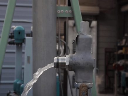
When testing the pressure relief valve, raise and lower the test lever several times. The lever will come away from the brass stem and allow hot water to come out of the end of the drainpipe. The water should flow through the pipe, and then you should turn down the pressure to stop the leak, replace the lever, and then increase the pressure.
One of the most common problems you can address with regular testing is the buildup of mineral salt, rust, and corrosion. When buildup occurs, the valve will become non-operational; the result can be an explosion. Regular testing helps you discover these issues sooner so you can combat them and keep your boiler and valve functioning properly. If no water flows through the pipe, or if there is a trickle instead of a rush of water, look for debris that is preventing the valve from seating properly. You may be able to operate the test lever a few times to correct the issue. You will need to replace the valve if this test fails.
When testing relief valves, keep in mind that they have two basic functions. First, they will pop off when the pressure exceeds its safety threshold. The valve will pop off and open to exhaust the excess pressure until the tank’s pressure decreases to reach the set minimum pressure. After this blowdown process occurs, the valve should reset and automatically close. One important testing safety measure is to use a pressure indicator with a full-scale range higher than the pop-off pressure.
Thus, you need to be aware of the pop-off pressure point of whatever tank or vessel you test. You always should remain within the pressure limits of the test stand and ensure the test stand is assembled properly and proof pressure tested. Then, take steps to ensure the escaping pressure from the valve is directed away from the operator and that everyone involved in the test uses safety shields and wears safety eye protection.
After discharge – Because pressure relief valves are designed to open automatically to relieve pressure in your system and then close, they may be able to open and close multiple times during normal operation and testing. However, when a valve opens, debris may get into the valve seat and prevent the valve from closing properly. After discharge, check the valve for leakage. If the leakage exceeds the original settings, you need to repair the valve.
According to local jurisdictional requirements – Regulations are in place for various locations and industries that stipulate how long valves may operate before needing to be repair or replaced. State inspectors may require valves to be disassembled, inspected, repaired, and tested every five years, for instance. If you have smaller valves and applications, you can test the valve by lifting the test lever. However, you should do this approximately once a year. It’s important to note that ASME UG136A Section 3 requires valves to have a minimum of 75% operating pressure versus the set pressure of the valve for hand lifting to be performed for these types of tests.
Depending on their service and application– The service and application of a valve affect its lifespan. Valves used for clean service like steam typically last at least 20 years if they are not operated too close to the set point and are part of a preventive maintenance program. Conversely, valves used for services such as acid service, those that are operated too close to the set point, and those exposed to dirt or debris need to be replaced more often.
Pressure relief valves serve a critical role in protecting organizations and employees from explosions. Knowing how and when to test and repair or replace them is essential.

Pressure safety valves are designed to protect process piping and equipment in case of an overpressure event. TEAM Valve Solutions inspects, tests, repairs and re-certifies safety valves at 17 service centers across three continents, and in our fleet of mobile facilities, all of which are audited under the jurisdiction of relevant governing bodies.
Our solutions cover all major safety valve brands and support our customers through an inventory of spare parts and loose-assembled valves. In addition, our facilities are audited and governed by the National Board of Boiler and Pressure Vessel Inspectors. Testing, repair, and assembly are performed under license and guidelines of NBIC, and ASME Section I and VIII.
To ensure accurate in-line setpoint verification, TEAM Valve Solutions utilizes Trevitest, the pioneering system for validating safety valve performance in Conventional and Nuclear Power plants, as well as in other industrial process facilities.


 8613371530291