
compressor safety valve adjustment supplier
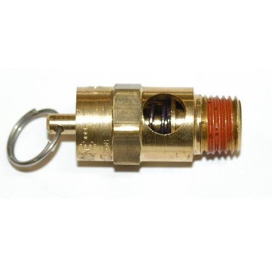
New replacement air compressor pressure safety relief valves. Using the correct one for your application is critical for safety. If you need help picking the right one, please call us for assistance.
In order to ensure that the maximum allowable accumulation pressure of any system or apparatus protected by a safety valve is never exceeded, careful consideration of the safety valve’s position in the system has to be made. As there is such a wide range of applications, there is no absolute rule as to where the valve should be positioned and therefore, every application needs to be treated separately.
A common steam application for a safety valve is to protect process equipment supplied from a pressure reducing station. Two possible arrangements are shown in Figure 9.3.3.
The safety valve can be fitted within the pressure reducing station itself, that is, before the downstream stop valve, as in Figure 9.3.3 (a), or further downstream, nearer the apparatus as in Figure 9.3.3 (b). Fitting the safety valve before the downstream stop valve has the following advantages:
• The safety valve can be tested in-line by shutting down the downstream stop valve without the chance of downstream apparatus being over pressurised, should the safety valve fail under test.
• When setting the PRV under no-load conditions, the operation of the safety valve can be observed, as this condition is most likely to cause ‘simmer’. If this should occur, the PRV pressure can be adjusted to below the safety valve reseat pressure.
Indeed, a separate safety valve may have to be fitted on the inlet to each downstream piece of apparatus, when the PRV supplies several such pieces of apparatus.
• If supplying one piece of apparatus, which has a MAWP pressure less than the PRV supply pressure, the apparatus must be fitted with a safety valve, preferably close-coupled to its steam inlet connection.
• If a PRV is supplying more than one apparatus and the MAWP of any item is less than the PRV supply pressure, either the PRV station must be fitted with a safety valve set at the lowest possible MAWP of the connected apparatus, or each item of affected apparatus must be fitted with a safety valve.
• The safety valve must be located so that the pressure cannot accumulate in the apparatus viaanother route, for example, from a separate steam line or a bypass line.
It could be argued that every installation deserves special consideration when it comes to safety, but the following applications and situations are a little unusual and worth considering:
• Fire - Any pressure vessel should be protected from overpressure in the event of fire. Although a safety valve mounted for operational protection may also offer protection under fire conditions,such cases require special consideration, which is beyond the scope of this text.
• Exothermic applications - These must be fitted with a safety valve close-coupled to the apparatus steam inlet or the body direct. No alternative applies.
• Safety valves used as warning devices - Sometimes, safety valves are fitted to systems as warning devices. They are not required to relieve fault loads but to warn of pressures increasing above normal working pressures for operational reasons only. In these instances, safety valves are set at the warning pressure and only need to be of minimum size. If there is any danger of systems fitted with such a safety valve exceeding their maximum allowable working pressure, they must be protected by additional safety valves in the usual way.
In order to illustrate the importance of the positioning of a safety valve, consider an automatic pump trap (see Block 14) used to remove condensate from a heating vessel. The automatic pump trap (APT), incorporates a mechanical type pump, which uses the motive force of steam to pump the condensate through the return system. The position of the safety valve will depend on the MAWP of the APT and its required motive inlet pressure.
This arrangement is suitable if the pump-trap motive pressure is less than 1.6 bar g (safety valve set pressure of 2 bar g less 0.3 bar blowdown and a 0.1 bar shut-off margin). Since the MAWP of both the APT and the vessel are greater than the safety valve set pressure, a single safety valve would provide suitable protection for the system.
Here, two separate PRV stations are used each with its own safety valve. If the APT internals failed and steam at 4 bar g passed through the APT and into the vessel, safety valve ‘A’ would relieve this pressure and protect the vessel. Safety valve ‘B’ would not lift as the pressure in the APT is still acceptable and below its set pressure.
It should be noted that safety valve ‘A’ is positioned on the downstream side of the temperature control valve; this is done for both safety and operational reasons:
Operation - There is less chance of safety valve ‘A’ simmering during operation in this position,as the pressure is typically lower after the control valve than before it.
Also, note that if the MAWP of the pump-trap were greater than the pressure upstream of PRV ‘A’, it would be permissible to omit safety valve ‘B’ from the system, but safety valve ‘A’ must be sized to take into account the total fault flow through PRV ‘B’ as well as through PRV ‘A’.
A pharmaceutical factory has twelve jacketed pans on the same production floor, all rated with the same MAWP. Where would the safety valve be positioned?
One solution would be to install a safety valve on the inlet to each pan (Figure 9.3.6). In this instance, each safety valve would have to be sized to pass the entire load, in case the PRV failed open whilst the other eleven pans were shut down.
If additional apparatus with a lower MAWP than the pans (for example, a shell and tube heat exchanger) were to be included in the system, it would be necessary to fit an additional safety valve. This safety valve would be set to an appropriate lower set pressure and sized to pass the fault flow through the temperature control valve (see Figure 9.3.8).

Adjustable Safety Valve - Air Compressor Adjustable Safety Valve | Over 40 Years Tube/Pipe Fittings for Medical & Semiconductor Industry Manufacturer | CHIBIN Machine Co., Ltd.
Based in Taiwan since 1980, CHIBIN Machine Co., Ltd. has been a stainless steel pipe fittings manufacturer. Their main pipe and tube fitting products, include Adjustable Safety Valve, tube fittings, compression fittings, rapid pneumatic fittings, push-in pneumatic fittings, hydraulic fittings, high pressure pipe fittings, quick couplings, nozzle and needle valves, which are specialized in medical and semiconductor sectors.
Conventionally when we talk about oil lubricated screw air compressor maintenance, it is mostly about replacing consumables such as filters and lubricant on time. While these consumables have a defined usable life and have a direct effect on the efficiency and the life of the air compressor itself when not replaced on time, there are a few critical valves in the air compressor that require maintenance as well. Compressor valves directly affect the efficiency, safety, and the functionality of the screw air compressor. Let us understand some of the commonly available valves in a screw air compressor, why they need maintenance, and discuss some of the frequently asked questions about screw air compressor valves.
A screw air compressor is very similar to a human heart. While a human heart has tricuspid, pulmonary, mitral, and aortic valves, a screw air compressor has four critical valves namely air inlet, minimum pressure, blow down, and safety valves.
Air inlet valve is also commonly known as the ‘Intake valve’ which is typically assembled on the airend’s intake. The air inlet valve of a conventional fixed speed screw air compressor controls the air intake into the compressor. It remains closed when the compressor starts to lower the starting load on the main motor and when the desired working pressure is attained in the compressed air circuit and thus enabling the compressor’s motor to run without any load. In some compressors that are capable of providing a variable output by modulating the amount of air it sucks in, the inlet valve holds various opening positions to regulate the volume of air entering the compressor. The effective performance of the inlet valve directly affects the compressor’s capacity and its power consumption during load and no-load conditions.
The minimum pressure valve is typically assembled on the exit of the air-oil separation tank of a compressor. The minimum pressure valve acts as a check valve preventing back flow of compressed air into the airend, retains a minimum pressure in the compressor system for lubrication, offers a restriction to avoid a collapse of the air-oil separation filter, and ensures a suitable velocity of flow across the air-oil separator that ensures efficient air-oil separation. The effective performance of the minimum pressure valve directly affects the compressor’s lubrication, air-oil separation efficiency, and power consumption during load and no-load conditions.
The blow down valve is typically found on a dedicated exhaust line from the air-oil separation tank. The blow down valve evacuates the compressed air in the air-oil separation tank each time the compressor runs on a no-load and when the compressor shuts down to ensure there is no back pressure when the compressor starts to load next time. The blow down valve of a conventional screw compressor is typically actuated by a solenoid valve. The effective performance of the blow down valve affects the compressor’s power consumption during un-load, capacity of the compressor when running on load, and the life of the motor.
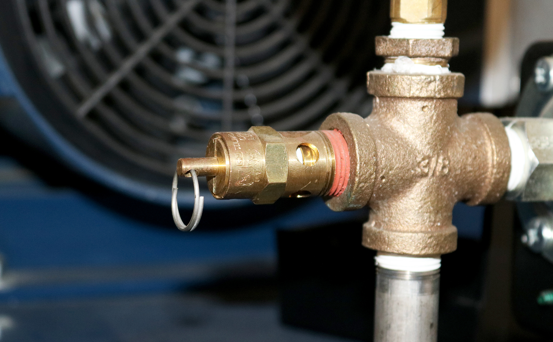
The safety valve is typically mounted directly on the air-oil separator tank. The only function of the safety valve is to blow off the compressed air in the air-oil separation tank when the pressure in the air-oil separation tank exceeds the set pressure of the safety valve and there by prevents the tank from cracking under high pressure. A malfunctioning safety valve affects the safe operation of the air compressor or results in leakage of compressed air continuously.
Though each compressor manufacturer has their own unique valve design, compressor valves in general contain moving parts such as springs, valve plates, and plungers that affect the opening and closing of the valves and rubber seals / seats that offer perfect sealing when the valves remain closed. These moving parts wear or lose their mechanical properties over a period of time and the sealing components typically ‘age’ over time and lose their effectiveness and will need to be replaced.
Compressor manufacturers typically design these components to operate efficiently for several thousand or millions of operation cycles. However, several factors such as variability in the demand pattern, sizing of the air compressor against a certain air demand, the environment in which the air compressor operates, promptness of preventive maintenance, etc. determine how long these valves efficiently operate.
Many times, it is difficult to identify a malfunctioning valve or a valve operating with worn-out parts as the compressor continues to generate air. The typical symptoms of a malfunctioning valve are loss in compressor"s capacity, increase in power consumption during load or/and unload, drop in discharge pressure, increase in oil carry-over and more load on motor. These symptoms are either difficult to notice or have other frequently common assignable causes such as air leak before suspecting the compressor valves.
Case studies show that operating a screw air compressor with a worn-out / malfunctioning valve could increase its overall power consumption by 10 - 15%. Power cost contributes to more than 75% of the compressor’s total life cycle cost over ten years and hence this is a significant impact. Unserviced valves also lower the life span of downstream accessories by half. In some cases, a malfunctioning safety valve may result in a catastrophe.
Air compressor manufacturers typically offer convenient valve maintenance kits for customers that contain the internal parts of the valve that wear or age out. Changing the valve kits is a much more sensible and economical option than changing the complete valve.
It is difficult or almost impossible to identify a malfunctioning valve unless it is opened for inspection. Hence it is absolutely mandatory that these valves are inspected for effectiveness every year and the internal moving parts replaced as a part of preventive maintenance once every year or two depending on the operating conditions of the air compressor. It is typical for compressor manufacturers to mandate a valve kit replacement once every two years as a proactive measure.
In particular, the safety valve must be inspected and certified every year per the local safety laws to ensure they are functional and efficient. Sometimes, replacing the safety valve entirely with a valid certificate for one year is more economical as the certification procedures could be equally expensive on an existing valve.
As stated before, it is challenging to identify a valve that is worn out unless it is opened and inspected, but there are a few indicators that a qualified compressor technician can use to deduct a malfunctioning valve.
Low duty cycle operation: A sophisticated screw air compressor in today’s day and age carries a convenient microprocessor-based human-machine interface that keeps track of operating hours of the compressor under load and un-load conditions and the number of load/unload counts the compressor is subjected to over a period of time. A higher un-load hours and load/unload count indicates that the air compressor is oversized against the actual air demand. This in turn indicates the air compressor ‘cycles’ frequently between load and un-load mode as opposed to running continuously on load. Every time a compressor ‘cycles’, the inlet valve, blow down valve, and minimum pressure valve is brought into play where their internals ‘actuate’. Frequent actuation of these valves results in a faster wear of the internals and hence results in shorter life.
High operating temperature: A compressor that runs on a high operating temperature affects the life of the valve’s sealing components, which causes them to ‘age’ fast.
Compressor not building pressure: If the air demand has not changed over time and the facility is relatively free of any air leakage, the air compressor is probably not delivering the rated output. There is a high probability that there is a malfunctioning valve.
Increase in compressor’s power consumption: An increase in the air compressor’s power consumption profile over a period of time where there has been no abnormal change in the air demand and usage pattern indicates an increase in either the load or un-load power. There is a high probability that this is because of a malfunctioning valve.
Based on the design philosophy adopted by the air compressor manufacturer, the oil lubricated screw air compressors could have a few more valves that are critical to functional performance that must be maintained as well. Some of the other valves frequently used in an air compressor are as follows:
Temperature control valve (also known as thermal valve) is used to regulate the flow of oil through the oil cooler based on the operating temperature.
Drain valves are used to drain lubricant at the time of lubricant change over or cleaning. Air compressors equipped with a moisture trap at the outlet of the after cooler also has a drain valve (automatic or timer based) to discharge water collected
The presence or absence of one of these valves and the type of actuation of these valves (electronic / mechanical) depends on air compressor’s design architecture. The Operation and Maintenance Manual (OMM) and the Piping and Instrumentation Diagram (P&ID) supplied by the air compressor manufacturer are excellent resources that explain the purpose, functioning, and maintenance requirements of these valves.
Many of the air compressor valves are highly specialized and exclusive. Their designs are usually complex and some even need special tools to service them. The internal components" build quality and material selection are extremely important and proprietary. Hence it is highly critical that only genuine valve kits issued by the air compressor manufacturer are used to maintain the valves. An inferior after-market replacement will most certainly compromise the performance of the entire compressor, void the original manufacturer"s warranty of the compressor, cause consequential damage to other parts of the compressor, and above all, be a safety hazard.
In conclusion, while it is important to change the screw air compressor"s filters and lubricants on time, it is equally important to perform preventive maintenance on these critical valves in a screw air compressor as recommended by the air compressor manufacturer. While the intake valve, minimum pressure valve, safety valve, and blowdown valve are critical to the performance and safety of the compressor, there could be other valves in the compressor that are critical and need maintenance. The air compressors sizing and the environment in which it operates are crucial factors that affect the life of the air compressor. Finally, it is critical to proactively service these valves using genuine kits issued by the compressor manufacturer to enable the air compressor performs efficiently and safely.
There are few components on an air compressor that can multi-task quite like the piloted unloader valve. This single component can activate an engine idle control, divert air from the tank when it reaches the top pressure setting and can reduce oil consumption by equalizing pressure between the pump and check valve. The following blog post will help you understand the piloted unloader valve by pointing out its components, explaining how it works and describing the adjustment process.
Piloted unloader valves combine a pilot valve and an unloader valve to run an air compressor continuously. While this type of valve is most commonly used on gas-powered air compressors, it can also be used on electric models. While the air compressor is running, the pilot remains closed until the pressure reaches the unload setting. When that happens, the pilot opens and pressurizes the unloader valve, causing the unloader valve to open and excess air from the compressor to vent to atmosphere. As the compressed air is used and the pressure drops to the load setting, the pilot closes and depressurizes the unloader valve. The unloader valve then closes and the pressure begins to build again and repeats the cycle.
Start engine/motor and observe tank pressure gauge. As tank pressure approaches 135 PSI, the unloader valve should begin unloading at felt muffler and cause gas engine to slow down to idle speed.
If pilot valve does not unload as tank pressure approaches 135 PSI, slowly turn top end setting (4) counterclockwise until pilot starts to unload prematurely (at 105 PSI).


 8613371530291