
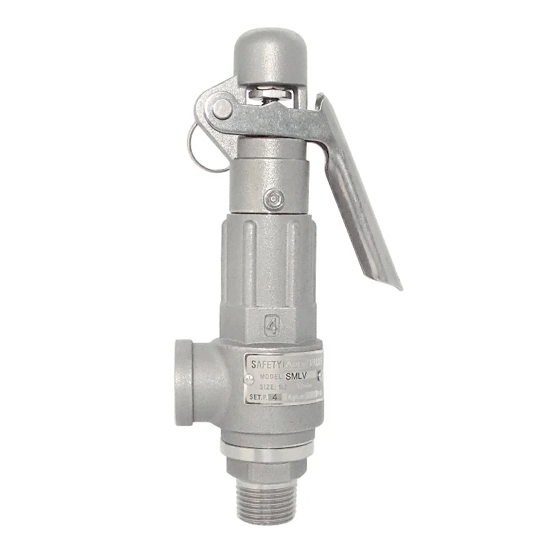
compressor safety valve adjustment made in china
The pressure reducing valve is an essential accessory of the pneumatic regulating valve. Its main function is to reduce the pressure of the air source and stabilize it to a fixed value, so that the regulating valve can obtain stable air source power for regulating control.
The pressure reducing valve is a valve that reduces the inlet pressure to a certain required outlet pressure through adjustment, and relies on the energy of the medium itself to automatically maintain a stable outlet pressure.
The main parameter of the air compressor safety valve is the displacement, which is determined by the diameter of the valve seat and the opening height of the valve disc.

The 2700 Series pressure relief valve, also known as an expansion relief valve, features a superior design that handles air, steam, vapor, and liquid services. In addition, the fixed blowdown design simplifies testing and repair, and the maximum interchangeability of parts allows for easy maintenance.
Expansion relief valves, also referred to as PRV’s, pressure relief valves, or safety valves, are designed to protect system tanks from overpressure, therefore a vital component. Overpressure can be caused by several things, including failure of an expansion vessel or a pressure-reducing valve.
Carrying on pressure tests on systems consists of adjusting the valve set pressure, performing a seat l,eakage test and a backpressure test. The set pressure test is always performed first.
Expansion relief valves are used in a range of industry demanding applications where pressure levels are critical for operation. Applications and industries include:
Air pressure relief valves, also known as PRVs or safety release valves, are installed to prevent pressure buildup. The valve opens slowly to release pressure when the level becomes too high.
If the pressure within an air compressor system gets too high, one of the components inside could explode. Essentially, pressure relief valves are designed to prevent uncontrolled depressurization events from occurring, protecting surrounding nearby equipment and employees during overpressure events.
Test the secondary pressure zone of all valves exceeding 1" inlet size with air or other suitable gas at a pressure of at least 30 psi. Use a suitable leak detection solution to verify tightness of all gasket joints and vent/drain plugs.
Expansion relief valves are often known as pressure relief valves and for a good reason. They come with a preset pressure built into their design to ensure once the valve recognizes the pressure limit, it opens to release the pressure-flow (fluid of compressed air) safely.
It’s advisable to permanently mount pressure relief valves in a vertical position so the spindle sits correctly and can operate effectively. Overtightening the valve can cause damage to the inlet and cause leakage too. For the inlet piping, keep it short and direct, it should have a shorter diameter than the valve, and it should always be far away from turbulence or vibration in the operating system.
A pressure relief valve can encounter overpressure or failure for many reasons, but the most common reasons are typically blocked discharge in the system, contaminants like dirt, rust, or sludge, or even valve misalignment can cause the pressure relief valve to fail. Maintenance and proper inspection periodically can help eliminate leakages, allowing a safe environment for operation and the operators.

This Control Devices SV-200 ASME safety valve has a brass body, a 200 psi relief pressure, a 1/4" male NPT threaded inlet connection, and a stainless steel pull ring for manual pressure relief. The valve"s brass body, brass valve seat, and the zinc plated steel spring resist corrosion and can be used in operating temperatures up to 250 degrees F. The preset relief pressure is accurate to within +/- 3 percent and a silicon O-ring provides a leak-proof seal to within +/- 10 percent of the relief pressure. This safety valve is American Society of Mechanical Engineers (ASME) safety rated and displays the UV mark for pressure vessel safety valves. It also displays the NB mark for certification in accordance with NB-501, National Board Certification of Pressure Relief Devices. This safety valve has a 76 Standard Cubic Feet per Minute (SCFM) flow rate and is suitable for low capacity pressure relief applications such as in home construction air compressors. Relief valves remove excess pressure or vacuum from a system. The valve openings allow fluids or gases to escape to decrease pressure, and then close once the valve reaches the reseating pressure limit. They also relieve excess vacuum by opening to release a gas into the system and then closing after it reaches its low-pressure limit. Some relief valves have an adjustment mechanism to set the pressure where the valve opens, making it suitable for various applications. Relief valves are rated according to the volume of liquid or gas that can flow through them and the material that the valve is constructed from must be suitable for the fluid or gas, which may be corrosive or at an extreme temperature, in which it operates. Relief valves are used in a variety of applications, such as air compressors, petrochemical and chemical manufacturing, natural gas processing, and power generation.

Safety should be the priority in any workplace environment, whether it’s a construction site, a factory or another setting. Business leaders want to make sure their employees are safe, maintain high morale among their workforce and reduce the possibility of damaged or broken machinery. By employing practical safety measures, your company can benefit from increased uptime and fewer repair or replacement expenses.
Having safety measures in place is especially important when working with air compressors and other high-powered machinery. Compressed air should be treated with the same amount of care as other energy sources, as misuse or a lack of the proper precautions can present risks. It’s essential that all operators have the proper training, have read all instruction manuals thoroughly and understand how to mitigate safety risks and potential damage. Manuals contain an abundance of valuable information and will tell you how to keep your compressors running for longer periods without damage or injury.
There are also plenty of other resources that discuss how to maintain safety when operating pneumatic tools and air compressors. This guide will take you through the basics of using an air compressor, what to check before use, what to monitor and how to keep operators and workspaces safe to minimize air compressor dangers.
Air compressors are useful for many jobs, but they can also become dangerous when not maintained properly or misused. Compressor machines, hoses, pneumatic tools and electric connections can all pose hazards in the workplace. Air compressor accidents could potentially cause harm to workers and machinery.
What are some of the most common hazards related to air compressors? They include electrical dangers, fumes, flying particles, high pressures and high noise levels.
Operators and workers can mitigate these dangers by following proper safety measures and air compressor precautions, which we will discuss later in the guide.
Depending on where you’re working, the intake air can contain pollutants and contaminants that are harmful to your health. From carbon monoxide to dust and debris, the air in the compressor collects from the surrounding space. To keep yourself safe while using the compressor unit, you must work in an area with proper airflow or natural air access, as well as protective gear, such as a respirator or dust mask.
While the likelihood of a workplace fatality due to an air compressor failure is low, it can happen in some extreme circumstances. If a compressor tank explodes, it can endanger your workers’ lives, but typically, the highest amount of danger lies with the operator. Due to the high pressures and pneumatic tools attached, operators must abide by all safety rules and regulations, including having the proper protective gear.
Every operator needs to undergo proper training and learn the relevant safety standards before using an air compressor. If you upgrade your air compressors or make any repairs, it’s essential to update operators on any changes so they know how to use the machine correctly and know what to look out for. It’s also important to check air compressor safety regulations from the Occupational Safety and Health Administration (OSHA) and ensure you’re in compliance with any that apply to your uses or machines.
The way your equipment and workspace are set up can have a significant impact on safety. Some air compressor and workspace setup tips to keep in mind include:
Component pressure ratings: Make sure that all components, including hoses, pipes and fittings, are rated for the maximum pressure of the air compressor.
Relief valves: Relief valves automatically release air if the pressure in the tank gets too high. These valves are important air compressor tank safety features, so you should never attempt to adjust, bypass or remove them.
Drain valves: If your compressor has an electric drain valve, make sure it is at least a foot and a half above the ground. Electric drain valves must be kept away from moisture.
Workspace humidity: It’s important to keep the humidity in your workspace from getting too high. To decrease the moisture in the air, try increasing air circulation in the workspace, operating your compressor for longer periods, using a peripheral crankcase heater or adding a dryer to your compressed air system.
Before using a compressor, you need to check various components to make sure the machine will work properly. To keep track of any issues and ensure you’ve looked at all the necessary areas, create an air compressor safety checklist for your operators to complete before each job. Some of the elements you may want to look at include:
Oil level: It’s essential to check and see if the machine has an appropriate amount of oil. Using it without an adequate amount of oil can ruin it to the point of requiring costly repairs or replacement. If it needs more oil, add oil to the reservoir but be careful not to overfill it. Also, be sure to keep oil from spilling onto the exterior of the compressor.
Fuel level:To run an air compressor, you need to have a sufficient amount of fuel. It can be a pain to have to refill in the middle of a job, as it requires you to stop, allow the compressor time to cool off and then refill the tank. Don’t refuel your air compressor when it’s on or has been shut off for only a short time. You should only conduct refuels and oil changes when the machine is cold.
Air filter:Whether you use a given compressor every day or only every once in a while, check the air filter before use. If it appears dirty or clogged, you should remove and wash it — if you have the right kind of screen — or replace it with a new filter.
Air connection:Before turning on your air compressor, make sure that it is securely connected to the air source. If the connection is weak or loose, the compressor may not perform as expected, and parts could disconnect, potentially leading to injury.
Outlets: Ensure your air compressor is only used with outlets that have the proper grounding. If you plug an air compressor into an incorrectly grounded outlet, it could damage the machine’s electrical circuitry and even cause a fire.
There are also air compression safety tips and procedures for particular parts of the compressor. Three of these components include the pressure regulation devices, air receivers and distribution lines. Each of these is significant in maintaining a healthy machine and operating it safely.
Valves:Ensure that the safety valves on your air tank are set to at least 10% or 15 psi — whichever is greater — above the operating pressure of the compressor but never higher than the air receiver’s working pressure limit. If using an air compressor in freezing temperatures, check that the safety valves are positioned in a way that prevents water from collecting inside the unit. If a valve freezes, thaw it and empty the compressor tank before reactivating the unit. The machine should also have shielded blowoff valves so sudden blowoffs don’t result in equipment damage or injury.
Air intake: The air intake should receive air only from clean, outdoor sources. Place a filter or screen at the intake valve to keep the intake air clean.
Speed: Check the manual that came with your compressor for the maximum recommended speed and ensure that you never run your compressor at speeds exceeding this level.
Draining:If your air compressor doesn’t have an automatic drain, be sure to drain the air receiver regularly so liquid does not build up inside of it.
Gauges and valves: Ensure that your air receiver has a pressure gauge and a safety valve that meets the American Society of Mechanical Engineers (ASME) standards.
Operators should also take certain precautions while operating air compressors and after completing a project using an air compressor. It’s essential to remain in control of compressor units at all times. Sound footing and standing on a level surface at a safe distance from the unit is crucial as is keeping your hands, clothing and hair away from the air nozzle and tools.
Also, be sure to wear the proper safety gear for the job. No matter what tool you’re using for a given project, it’s vital to wear protective gear for your ears and eyes at all times. According to the Center for Disease Control, an estimated 22 million workers face exposure to potentially harmful noise every year. The risks involved with failing to wear hearing guards might not always be apparent at first, but adverse effects due to exposure to noise are often experienced later, in some cases years down the line. Personal protective equipment (PPE) to consider includes goggles, face masks, rubber or leather gloves, steel-toed shoes and leather or PVC aprons. Cotton clothing is not an effective barrier to compressed air. Cover any part of the body that is at risk of coming into contact with compressed air or flying particles.
To prevent safety issues, it’s crucial to keep an eye out for any potential issues while you’re using an air compressor. Once you start the machine and begin your work, be sure to check the following items consistently:
Surroundings: In addition to managing your own safety, keep an eye out for other workers and ensure you’re keeping the surrounding area safe. Make sure that all your hoses, cables and wires are tucked away where no one can trip on them and that you keep your area clean.
Voltage:Pay close attention to your air compressor’s voltage. If repairs are needed, power down the machine, lock and tag out all power sources and release all pressure from the compressor. If your compressor is designed for indoor use, don’t use it outdoors, as rain or wet conditions can cause electrical problems.
Performing preventative maintenance is essential to keeping your compressor running smoothly and safely. It can increase the longevity of your machine and improve its capabilities. Running a clean, well-kept machine will also promote the wellbeing of your workers and operators and help manage air compressor risks.
Receive the proper training:Anyone performing maintenance on an air compressor should have received the appropriate training to ensure they conduct maintenance tasks correctly and safely.
Follow the manufacturer’s recommendations: To ensure safety in maintenance and operation, it’s important to follow the care and maintenace recommendations of your compressor’s manufacturer.
Disconnect power: Before performing maintenance work, shut off the machine and disconnect it from all power sources. Lock open the electrical switch for the compressor and tag it so no one starts it by mistake.
Clean the unit properly:Cleaning your air compressor regularly will improve its performance and extend its life. When it comes to cleaning carbon remnants from the various parts of an air compressor, it’s safe to use soapy water or a lye solution, but you should never use anything flammable, such as kerosene. Following every cleaning, completely purge the air system.
Lubricate properly:Don’t use oils with low flash points to lubricate compressor parts. These oils could combust due to the high temperatures produced by air compressors during operation. It’s essential, however, to keep parts lubricated with the proper oils and to avoid over-lubrication to prevent corrosion.
Take steps to prevent rust: One of the most dangerous possibilities when it comes to air compressors is a rusty tank. Rust increases the unit’s chances of combusting, putting anyone nearby in danger. To prevent rust due to the accumulation of liquid, use the underside valve to drain the tank daily. If a tank becomes rusted, don’t attempt to repair it. A rusted tank requires replacement.
Although proper maintenance can help extend the life of your air compressor, you may still occasionally need to troubleshoot issues. Follow these compressed air safety tips when troubleshooting your equipment:
Shut down your compressor:Turn off your compressor, disconnect it from power and bleed any remaining air pressure before doing any troubleshooting or repair work. Make sure that the shutoff valve is always within reach in case something goes wrong during operation.
Follow safety procedures for hose malfunctions:If a hose malfunctions or comes apart at the coupling, you can prevent whipping with two components. One is an air fuse of the proper size, which you should install in the hose upstream. The other is a whip-inhibiting device that is placed along the coupling of a hose. If an air hose does start whipping around uncontrollably or another similar air hose problem occurs, don’t try to stop and control it by grabbing the hose. To prevent injury, turn off the air source before touching the hose.
Use reliable parts: If a component becomes damaged or needs to be replaced for any reason, use only reliable, high-quality parts that are the correct size, material and type for your machine. Using the wrong parts or low-quality components can result in decreased compressor performance, damage to your equipment and safety hazards.
As one of the world’s leading sellers of compressed air products for nearly 100 years, Quincy Compressor offers an array of machines and parts for many industries. With our one-of-a-kind offers and round-the-clock support, we’ve supplied and serviced businesses in the automotive, manufacturing and construction sectors, among others.
People have various uses for compressed air, and at Quincy, we’ve got them all covered. With Quincy, there’s no application too demanding for our top-of-the-line products to handle with utmost ease and maximum efficiency. Everyone who shops with us receives support from our authorized partners, day or night, as well as industry-leading warranties on select compressor products.
If you’re in the market for compressed air devices or related equipment, explore our website, where you can download whitepapers for more information on our wide range of products. You can also contact your local authorized Quincy Compressor distributor for air compressor sales and service in your area.

The purpose of this utility model is directed to the deficiencies in the prior art, there is provided a kind of compressor housing installs relief valve, work
The installation of contracting machine, the position of the top pin on L-type connecting plate can also be entered according to the position of compressor housing screwed hole
Row adjustment, recycles the promotion of jacking cylinder to push against compressor housing, meets Multiple Type compressor and uses a secondary frock to press from both sides
Jacking cylinder is arranged on right installing plate, is fixedly connected with right installing plate by bolt;The adjustment block is fixedly mounted on top
Preferably, described L-type connecting plate can be adjusted according to the position of compressor housing upper installing hole, and top pin is worn
Preferably, the outer circumference surface of described semicircle limited block is placed in the inner chamber of compressor housing and limits housing
Inner chamber pass through semicircle limited block after, inner chamber plane is supported to left installing plate, the point location of compressor second is realized, while compressor
Housing passes through middle V-block and realizes support and position, after compressor housing is fixed, using the thrust of jacking cylinder by compressor
The position of top pin is installed, the need for realizing that different model compressor housing installs relief valve and technique mouth on fishplate bar.

In addition to the small installation space of the above-mentioned compressors, they should be completely covered by an acoustic enclosure to reduce noise emissions. In order to reduce the size of the very cost-intensive sound enclosure, AERZEN requires special valves that are adapted to the available small installation space. Compressors are discontinuous machines for pressure generation.
In order to ensure that occurring pulsations do not impair the function of the safety valve, the set pressure of the valve is adjusted accordingly and an appropriate distance to the pressure line is ensured by design.
The LESER solutionAs a renowned manufacturer of safety valves, it is advantageous to be able to react flexibly to the above-mentioned concerns, primarily to the small installation space, with its portfolio. Being able to change the installation position of safety valves is a clear advantage for the compressor designer. They are much more variable in their design and construction options and can also respond more flexibly to special customer specifications. If the progressive modularization of compressors requires more compact designs, safety valves in different mounting positions, for example, can be an answer to the problem, unlike the classic upright position. In addition, the spindle guide plays a special role here. The friction at the guiding points must be reduced as much as possible so that the spindle runs smoothly. Otherwise, a safety valve can only be installed vertically.
Why LESER safety valves?For a global acting OEM like AERZEN, a specialist like LESER, who has not only the knowledge but also the necessary approvals, is an important component for success. LESER offers a global approval concept that allows safety valves to be used regardless of location. When ordering safety valves, only the applicable regulations must be specified in order to ensure appropriate labeling and material selection. In addition, LESER has tested and approved further installation positions in addition to the conventional installation situation, standing on the inlet pipeline. For example, some types of valves may be installed with a horizontal stem or even upside down, e.g. Types 526 and 441. For horizontal installation, care must be taken to align the outlet. Liquids, e.g. in the form of condensate, should be able to drain off downwards to avoid back pressures and even corrosion. When installed upside down, the inverted weight forces are corrected by correction factors. LESER offers not only safety valves with basic documentation and accessories but also other special documentation and options. From the “Fugitive Emission Test” with helium up to 3.2 ship class castings and from back pressures up to more than 200 bar-g to high pressure heating jackets for up to 30 bar-g, LESER sales engineers develop solutions for customer specific applications as described above for AERZEN.

Valves control the flow of fuel vapor into the combustion chamber and the flow of exhaust gases leaving the engine. Faulty or dirty valves may stick and can develop pits, cracks or grooves that cause the engine to lose power and fuel efficiency.
Whether you’re having trouble with your engine or wanting to go through your routine valve maintenance, make sure you have our step-by-step guide on how to check your engine valves. From removing the valve, to cleaning for inspection, find information for valve maintenance for your Briggs & Stratton engines.
In order to properly inspect your engine valves for maintenance or repair, you need to remove them from the engine. Find the type of engine valve retainer and follow our step-by-step guide below
Step 3: Remove the cylinder head bolts and take out other bolts from the engine components to reach the valve chamber. Label the bolts if necessary, to ensure proper installation later, since they may be of different lengths.
Step 2: After removing the spark plug and securing the spark plug lead away from the spark plug, adjust the jaws of the valve spring compressor (part number 19063) until they touch the top and bottom of the valve chamber
Removing the valves for keyhole retainers requires some patience. Remember that the retainer’s key-shaped slot will help you slip the retainer off the valve stem, even when the retainer is hidden from your view by the valve spring compressor.
Step 2: Slip the upper jaw of the valve spring compressor over the top of the valve chamber and the lower jaw between the spring and retainer. If the engine design does not permit the upper jaw to fit over the top of the valve chamber, insert the upper jaw into the chamber over the top of the spring, so that the spring is between the tool"s jaws
Step 3: Rotate the handle on the valve spring compressor clockwise to compress the spring. Then, slide the retainer off the valve by shifting it with needle nose pliers so that the large part of the keyhole is directly over the stem. Use the pliers to remove the retainer from the valve chamber.
Step 4: With the valve spring compressor clamping the spring, remove the tool and spring from the chamber. Then, slowly crank open the valve spring compressor to release the tension and remove the spring
Overhead valve designs vary from one engine model to another. The parts and servicing steps in your overhead valve cylinder may differ from the approach that follows, which is based on the Briggs & Stratton Intek 6-HP single-cylinder OHV. The Intek does not require the use of a valve spring compressor, making valve removal and installation simple.
Step 6: Use your thumbs to press in on the spring retainer and valve spring over one of the valves. With the valve spring compressed, remove the retainer.
If your engine uses a keyhole retainer, line up the large slot in the retainer with the valves stem and release the spring slowly so that the stem slips through the large slot. Then, repeat the procedure for the other valve.
Step 9: Remove and inspect the valves, guides and seats following the steps below. The intake and exhaust valves often are made of different steel alloys and may be different colors.
Gummy deposits on the intake valve go hand in hand with a decrease in engine performance, often because the engine has been run on old gasoline. Hard deposits on either valve suggest burning oil, which has several possible causes.
Step 1: Check the valve face for an irregular seating pattern. The pattern around the face should be even with the valve head and of equal thickness all the way around. It there are stubborn deposits, clean the valve with a wire brush and solvent, soaking the parts for several hours if necessary, to loosen hardened grit.
Step 2: Run a fingernail or credit card along the valve stem once you have cleaned it. If you feel a ridge, the valve stem is worn and should be replaced. The valve guide may also be worn and in need of a replacement.
Step 4: Examine the surfaces of the valve face and seat. An uneven wear pattern tells you it"s time to replace them or resurface the seat and replace the valve.
If there are no signs of damage or valves wearing out after inspection, you can tune up the valves and seats so that the valves seal effectively (also known as “lapping the valves”).
You can smooth out minor scoring and pitting of the valve face and seat to restore a valve"s ability to seal the combustion chamber by lapping the valves. While lapping valves, make sure to check your progress often because it’s easy to remove the carbon building as well as the metal, further damaging the valve or seat.
Step 1: Apply a small amount of valve lapping compound (part number 94150) - a fine, but abrasive paste- to the valve face and insert the valve into the valve guide.
Step 2: Wet the end of the lapping tool suction cup and place it on the valve head. Spin the valve back and forth between your hands several times. Lift the tool, rotate 1/4 turn and spin again.
Step 3: Clean the surface frequently and check your progress. Lap the valve just enough to create a consistent and even pattern around the valve face.
Step 4: Once lapping is completed, clean the valves thoroughly with solvent to ensure that ALL of the abrasive residue is removed. Any particles that remain can rapidly damage the valves and other engine components.
Step 4: If pins are used, insert each pin with needle nose pliers. If automotive-type retainers are used, place the retainers in the valve stem groove.
Step 1: Valves with keyhole retainers do not require an additional retainer. Compress the keyhole retainer and spring with the compressor tool - the large hole should face the opening in the tool - until the spring is solid.
Step 1: Check that valve stems and guides are free of debris and burrs. Then, lightly coat the valve stems with valves guide lubricant and insert them in the cylinder head, taking care to place the correct valve in each valve guide.
Step 3: Lubricate the inside diameter of each valve stem seal (if equipped) with engine oil and install the seals on the valve stems. Press them into place.
Use both thumbs to compress the spring until the valve stem extends through the large end of the keyhole slot. Check that the retainer is fully engaged in the valve stem groove. Repeat this step for the other valve.
Step 5: Coat the threads of the cylinder head bolts with valve guide lubricant. Install a new cylinder head gasket on the cylinder, insert the bolts in the cylinder and position the cylinder head on the cylinder.
Step 8: Install the caps on the ends of the valves and wipe away any lubricant. Then, install the rocker arm assemblies while holding the rocker arms against the valve cap and push rod.
Step 8: Install the caps on the ends of the valves and wipe away any lubricant. Then, install the rocker arm assemblies while holding the rocker arms against the valve cap and push rod.
Since lapping valves removes a small amount of material from the surfaces of the valve face and valve seat, you may need to adjust the tappet clearances - the spacing between the valve stem and the tappet - after lapping and reinstalling the valves. Ask your Briggs & Stratton Authorized Dealer near you for the correct tappet clearance for your engine.
Step 1: With each valve installed in its proper guides in the cylinder, turn the crankshaft (clockwise as viewed from the flywheel end of the crankshaft) to top dead center. Both valves should be closed. Then, turn the crankshaft past top dead center until the piston is 1/4" down from the top of the cylinder.
Step 3: If clearance is insufficient, remove the valve and grind or file the end of the valve stem square to increase the clearance. Check the length frequently as it is easy to remove too much metal.
Step 4: Once the individual valve parts have been thoroughly cleaned, lubricate the valve stems and guides, using valve guide lubricant. Then, make certain there is NO lubricant on the ends of the valve stems or tappets.
Step 3: Check the valve clearance by placing a feeler gauge between the valve head and the rocker arm. Clearances differ for the two valves and typically range from .002 - .004" to .005 - .007".

Safety valves are an assembly that is mandatory on every breathing air compressor and high pressure compressor. The set pressure of the valve can be adjusted to the final pressure by means of spring force. High-pressure compressors, if not shut off, will continue to generate pressure until some component on the compressor breaks or the drive motor is overloaded. For this reason, breathing air compressors are equipped with two safety devices. The electrical limit switch and the safety valve. Some compressors also have additional safety valves in the piping at each compressor stage. Safety valves are available for the two most used pressure stages 200bar ( 232bar ) and 300bar ( 330bar ) in our online store. In addition to the safety valve, the pressure gauge for displaying the pressure of the compressed gas is an important piece of equipment for high-pressure compressors and breathing air compressors.

Conventionally when we talk about oil lubricated screw air compressor maintenance, it is mostly about replacing consumables such as filters and lubricant on time. While these consumables have a defined usable life and have a direct effect on the efficiency and the life of the air compressor itself when not replaced on time, there are a few critical valves in the air compressor that require maintenance as well. Compressor valves directly affect the efficiency, safety, and the functionality of the screw air compressor. Let us understand some of the commonly available valves in a screw air compressor, why they need maintenance, and discuss some of the frequently asked questions about screw air compressor valves.
A screw air compressor is very similar to a human heart. While a human heart has tricuspid, pulmonary, mitral, and aortic valves, a screw air compressor has four critical valves namely air inlet, minimum pressure, blow down, and safety valves.
Air inlet valve is also commonly known as the ‘Intake valve’ which is typically assembled on the airend’s intake. The air inlet valve of a conventional fixed speed screw air compressor controls the air intake into the compressor. It remains closed when the compressor starts to lower the starting load on the main motor and when the desired working pressure is attained in the compressed air circuit and thus enabling the compressor’s motor to run without any load. In some compressors that are capable of providing a variable output by modulating the amount of air it sucks in, the inlet valve holds various opening positions to regulate the volume of air entering the compressor. The effective performance of the inlet valve directly affects the compressor’s capacity and its power consumption during load and no-load conditions.
The minimum pressure valve is typically assembled on the exit of the air-oil separation tank of a compressor. The minimum pressure valve acts as a check valve preventing back flow of compressed air into the airend, retains a minimum pressure in the compressor system for lubrication, offers a restriction to avoid a collapse of the air-oil separation filter, and ensures a suitable velocity of flow across the air-oil separator that ensures efficient air-oil separation. The effective performance of the minimum pressure valve directly affects the compressor’s lubrication, air-oil separation efficiency, and power consumption during load and no-load conditions.
The blow down valve is typically found on a dedicated exhaust line from the air-oil separation tank. The blow down valve evacuates the compressed air in the air-oil separation tank each time the compressor runs on a no-load and when the compressor shuts down to ensure there is no back pressure when the compressor starts to load next time. The blow down valve of a conventional screw compressor is typically actuated by a solenoid valve. The effective performance of the blow down valve affects the compressor’s power consumption during un-load, capacity of the compressor when running on load, and the life of the motor.
The safety valve is typically mounted directly on the air-oil separator tank. The only function of the safety valve is to blow off the compressed air in the air-oil separation tank when the pressure in the air-oil separation tank exceeds the set pressure of the safety valve and there by prevents the tank from cracking under high pressure. A malfunctioning safety valve affects the safe operation of the air compressor or results in leakage of compressed air continuously.
Though each compressor manufacturer has their own unique valve design, compressor valves in general contain moving parts such as springs, valve plates, and plungers that affect the opening and closing of the valves and rubber seals / seats that offer perfect sealing when the valves remain closed. These moving parts wear or lose their mechanical properties over a period of time and the sealing components typically ‘age’ over time and lose their effectiveness and will need to be replaced.
Compressor manufacturers typically design these components to operate efficiently for several thousand or millions of operation cycles. However, several factors such as variability in the demand pattern, sizing of the air compressor against a certain air demand, the environment in which the air compressor operates, promptness of preventive maintenance, etc. determine how long these valves efficiently operate.
Many times, it is difficult to identify a malfunctioning valve or a valve operating with worn-out parts as the compressor continues to generate air. The typical symptoms of a malfunctioning valve are loss in compressor"s capacity, increase in power consumption during load or/and unload, drop in discharge pressure, increase in oil carry-over and more load on motor. These symptoms are either difficult to notice or have other frequently common assignable causes such as air leak before suspecting the compressor valves.
Case studies show that operating a screw air compressor with a worn-out / malfunctioning valve could increase its overall power consumption by 10 - 15%. Power cost contributes to more than 75% of the compressor’s total life cycle cost over ten years and hence this is a significant impact. Unserviced valves also lower the life span of downstream accessories by half. In some cases, a malfunctioning safety valve may result in a catastrophe.
Air compressor manufacturers typically offer convenient valve maintenance kits for customers that contain the internal parts of the valve that wear or age out. Changing the valve kits is a much more sensible and economical option than changing the complete valve.
It is difficult or almost impossible to identify a malfunctioning valve unless it is opened for inspection. Hence it is absolutely mandatory that these valves are inspected for effectiveness every year and the internal moving parts replaced as a part of preventive maintenance once every year or two depending on the operating conditions of the air compressor. It is typical for compressor manufacturers to mandate a valve kit replacement once every two years as a proactive measure.
In particular, the safety valve must be inspected and certified every year per the local safety laws to ensure they are functional and efficient. Sometimes, replacing the safety valve entirely with a valid certificate for one year is more economical as the certification procedures could be equally expensive on an existing valve.
As stated before, it is challenging to identify a valve that is worn out unless it is opened and inspected, but there are a few indicators that a qualified compressor technician can use to deduct a malfunctioning valve.
Low duty cycle operation: A sophisticated screw air compressor in today’s day and age carries a convenient microprocessor-based human-machine interface that keeps track of operating hours of the compressor under load and un-load conditions and the number of load/unload counts the compressor is subjected to over a period of time. A higher un-load hours and load/unload count indicates that the air compressor is oversized against the actual air demand. This in turn indicates the air compressor ‘cycles’ frequently between load and un-load mode as opposed to running continuously on load. Every time a compressor ‘cycles’, the inlet valve, blow down valve, and minimum pressure valve is brought into play where their internals ‘actuate’. Frequent actuation of these valves results in a faster wear of the internals and hence results in shorter life.
High operating temperature: A compressor that runs on a high operating temperature affects the life of the valve’s sealing components, which causes them to ‘age’ fast.
Compressor not building pressure: If the air demand has not changed over time and the facility is relatively free of any air leakage, the air compressor is probably not delivering the rated output. There is a high probability that there is a malfunctioning valve.
Increase in compressor’s power consumption: An increase in the air compressor’s power consumption profile over a period of time where there has been no abnormal change in the air demand and usage pattern indicates an increase in either the load or un-load power. There is a high probability that this is because of a malfunctioning valve.
Based on the design philosophy adopted by the air compressor manufacturer, the oil lubricated screw air compressors could have a few more valves that are critical to functional performance that must be maintained as well. Some of the other valves frequently used in an air compressor are as follows:
Temperature control valve (also known as thermal valve) is used to regulate the flow of oil through the oil cooler based on the operating temperature.
Drain valves are used to drain lubricant at the time of lubricant change over or cleaning. Air compressors equipped with a moisture trap at the outlet of the after cooler also has a drain valve (automatic or timer based) to discharge water collected
The presence or absence of one of these valves and the type of actuation of these valves (electronic / mechanical) depends on air compressor’s design architecture. The Operation and Maintenance Manual (OMM) and the Piping and Instrumentation Diagram (P&ID) supplied by the air compressor manufacturer are excellent resources that explain the purpose, functioning, and maintenance requirements of these valves.
Many of the air compressor valves are highly specialized and exclusive. Their designs are usually complex and some even need special tools to service them. The internal components" build quality and material selection are extremely important and proprietary. Hence it is highly critical that only genuine valve kits issued by the air compressor manufacturer are used to maintain the valves. An inferior after-market replacement will most certainly compromise the performance of the entire compressor, void the original manufacturer"s warranty of the compressor, cause consequential damage to other parts of the compressor, and above all, be a safety hazard.
In conclusion, while it is important to change the screw air compressor"s filters and lubricants on time, it is equally important to perform preventive maintenance on these critical valves in a screw air compressor as recommended by the air compressor manufacturer. While the intake valve, minimum pressure valve, safety valve, and blowdown valve are critical to the performance and safety of the compressor, there could be other valves in the compressor that are critical and need maintenance. The air compressors sizing and the environment in which it operates are crucial factors that affect the life of the air compressor. Finally, it is critical to proactively service these valves using genuine kits issued by the compressor manufacturer to enable the air compressor performs efficiently and safely.


 8613371530291