
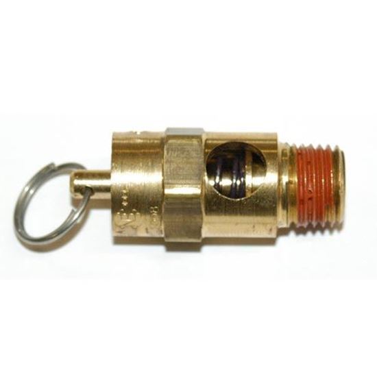
compressor safety valve adjustment price

New replacement air compressor pressure safety relief valves. Using the correct one for your application is critical for safety. If you need help picking the right one, please call us for assistance.

I can see there are markings on the valve,but I can"t read them in situ. Once I get the new valve, I"ll read the markings on the existing valve once I have it out.

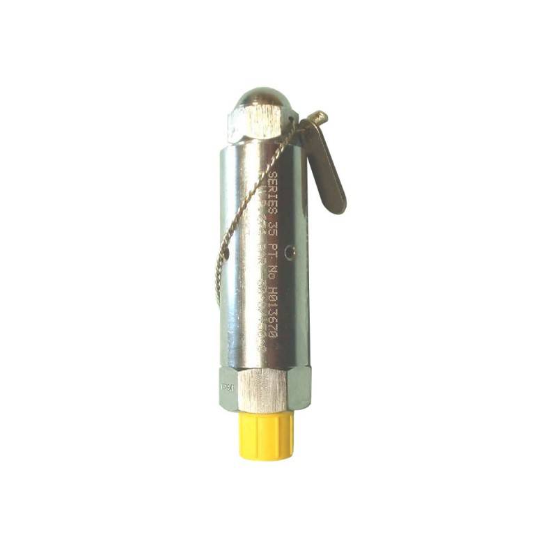
An OSHA COMPRESSED AIR SAFETY SHUT-OFF VALVES should be placed immediately after the air control shut off valve and before the hose on a compressor, and after each discharge port that a hose is connected to.
Before starting the compressor the air control valve should be closed completely. When the compressor unloads, open the air shut off control valve very slowly. Full port ball valves tend to work better than gate or butterfly type valves.
The air shut off control valve must be fully open for the OSHA COMPRESSED AIR SAFETY SHUT-OFF VALVES to work. Some portable air compressor manufacturers recommend start-up with the air control valve slightly open. In this case you may have to close the valve and reopen it slowly to the full open position, or wait for the safety shut-off valve to reset itself.
If the OSHA COMPRESSED AIR SAFETY SHUT-OFF VALVES fails to operate despite meeting all condi-tions, check the hose line for obstructions or a hose mender restricting normal air flow.
• Turn on air supply slowly (to avoid tripping OSHA safety valve). Prior to fully reaching operation conditions, the OSHA COMPRESSED AIR SAFETY SHUT-OFF VALVES should suddenly activate and stop air flow.
• If the OSHA COMPRESSED AIR SAFETY SHUT-OFF VALVE is not activated the unit should be disconnected and the lower flow range OSHA COMPRESSED AIR SAFETY SHUT-OFF VALVES should be used. This means you need to use a different valve with a lower scfm range.
• At temperatures below 40°F ensure that OSHA COMPRESSED AIR SAFETY SHUT-OFF VALVES are not subject to icy conditions which may prevent proper functioning.
In order to ensure that the maximum allowable accumulation pressure of any system or apparatus protected by a safety valve is never exceeded, careful consideration of the safety valve’s position in the system has to be made. As there is such a wide range of applications, there is no absolute rule as to where the valve should be positioned and therefore, every application needs to be treated separately.
A common steam application for a safety valve is to protect process equipment supplied from a pressure reducing station. Two possible arrangements are shown in Figure 9.3.3.
The safety valve can be fitted within the pressure reducing station itself, that is, before the downstream stop valve, as in Figure 9.3.3 (a), or further downstream, nearer the apparatus as in Figure 9.3.3 (b). Fitting the safety valve before the downstream stop valve has the following advantages:
• The safety valve can be tested in-line by shutting down the downstream stop valve without the chance of downstream apparatus being over pressurised, should the safety valve fail under test.
• When setting the PRV under no-load conditions, the operation of the safety valve can be observed, as this condition is most likely to cause ‘simmer’. If this should occur, the PRV pressure can be adjusted to below the safety valve reseat pressure.
Indeed, a separate safety valve may have to be fitted on the inlet to each downstream piece of apparatus, when the PRV supplies several such pieces of apparatus.
• If supplying one piece of apparatus, which has a MAWP pressure less than the PRV supply pressure, the apparatus must be fitted with a safety valve, preferably close-coupled to its steam inlet connection.
• If a PRV is supplying more than one apparatus and the MAWP of any item is less than the PRV supply pressure, either the PRV station must be fitted with a safety valve set at the lowest possible MAWP of the connected apparatus, or each item of affected apparatus must be fitted with a safety valve.
• The safety valve must be located so that the pressure cannot accumulate in the apparatus viaanother route, for example, from a separate steam line or a bypass line.
It could be argued that every installation deserves special consideration when it comes to safety, but the following applications and situations are a little unusual and worth considering:
• Fire - Any pressure vessel should be protected from overpressure in the event of fire. Although a safety valve mounted for operational protection may also offer protection under fire conditions,such cases require special consideration, which is beyond the scope of this text.
• Exothermic applications - These must be fitted with a safety valve close-coupled to the apparatus steam inlet or the body direct. No alternative applies.
• Safety valves used as warning devices - Sometimes, safety valves are fitted to systems as warning devices. They are not required to relieve fault loads but to warn of pressures increasing above normal working pressures for operational reasons only. In these instances, safety valves are set at the warning pressure and only need to be of minimum size. If there is any danger of systems fitted with such a safety valve exceeding their maximum allowable working pressure, they must be protected by additional safety valves in the usual way.
In order to illustrate the importance of the positioning of a safety valve, consider an automatic pump trap (see Block 14) used to remove condensate from a heating vessel. The automatic pump trap (APT), incorporates a mechanical type pump, which uses the motive force of steam to pump the condensate through the return system. The position of the safety valve will depend on the MAWP of the APT and its required motive inlet pressure.
This arrangement is suitable if the pump-trap motive pressure is less than 1.6 bar g (safety valve set pressure of 2 bar g less 0.3 bar blowdown and a 0.1 bar shut-off margin). Since the MAWP of both the APT and the vessel are greater than the safety valve set pressure, a single safety valve would provide suitable protection for the system.
Here, two separate PRV stations are used each with its own safety valve. If the APT internals failed and steam at 4 bar g passed through the APT and into the vessel, safety valve ‘A’ would relieve this pressure and protect the vessel. Safety valve ‘B’ would not lift as the pressure in the APT is still acceptable and below its set pressure.
It should be noted that safety valve ‘A’ is positioned on the downstream side of the temperature control valve; this is done for both safety and operational reasons:
Operation - There is less chance of safety valve ‘A’ simmering during operation in this position,as the pressure is typically lower after the control valve than before it.
Also, note that if the MAWP of the pump-trap were greater than the pressure upstream of PRV ‘A’, it would be permissible to omit safety valve ‘B’ from the system, but safety valve ‘A’ must be sized to take into account the total fault flow through PRV ‘B’ as well as through PRV ‘A’.
A pharmaceutical factory has twelve jacketed pans on the same production floor, all rated with the same MAWP. Where would the safety valve be positioned?
One solution would be to install a safety valve on the inlet to each pan (Figure 9.3.6). In this instance, each safety valve would have to be sized to pass the entire load, in case the PRV failed open whilst the other eleven pans were shut down.
If additional apparatus with a lower MAWP than the pans (for example, a shell and tube heat exchanger) were to be included in the system, it would be necessary to fit an additional safety valve. This safety valve would be set to an appropriate lower set pressure and sized to pass the fault flow through the temperature control valve (see Figure 9.3.8).
When was the last time that you had your vehicle"s valves adjusted? Known as a valve adjustment or valve clearance adjustment, it"s a routine form of maintenance recommended for most vehicles with a combustion engine. Unfortunately, it"s also something that many motorists overlook. It"s not until they experience problems with their vehicle that they realize the need for a valve adjustment. To learn more about valve adjustments and how they work, keep reading.
So, what is a valve adjustment exactly? To better understand this maintenance procedure, you must first look at the valve system of a typical combustion engine. The valve system consists of pushrods, lifters and rocker arms. Supported by lifters and rocker arms, the pushrods move up and down to open the intake valve. Over time, however, it"s not uncommon for the clearance between these components to increase (or decrease in some cases). A valve adjustment, however, is designed to move the valves into the appropriate position, thereby eliminating problems associated with excessive clearance.
If your vehicle"s engine needs a valve adjustment, you may hear a loud clanging or clinking sound originating in the engine bay. This occurs because of the valves large clearance space. Since the pushrods aren"t secure in place, they don"t glide smoothly up and down.
Another common sign your vehicle"s engine needs a valve adjustment is rough idling. If the valves don"t open the intake and exhaust at the right time, it will restrict airflow into the engine, which may manifest as rough idling.
Incorrect valve clearance can also lead to oil consumption. If you notice the level on your vehicle"s dipstick gradually lowering, you should consider taking your vehicle to the shop for a valve inspection, and if necessary, a valve adjustment as well.
You should refer to your owner"s manual to find out when, exactly, your vehicle"s valves should be inspected by a mechanic. Some automakers recommend a valve inspection every 60,000 miles, whereas others recommend a valve inspection every 100,000 miles. During an inspection, a professional mechanic will determine whether your vehicle"s engine needs a valve adjustment.
The cost of a valve adjustment varies depending on several factors, including the make and model of your vehicle, the mechanic from whom you purchase the service, your geographic location and more. With that said, the average cost of a valve adjustment is about $150 to $300, assuming no other work or parts are required.

There are few components on an air compressor that can multi-task quite like the piloted unloader valve. This single component can activate an engine idle control, divert air from the tank when it reaches the top pressure setting and can reduce oil consumption by equalizing pressure between the pump and check valve. The following blog post will help you understand the piloted unloader valve by pointing out its components, explaining how it works and describing the adjustment process.
Piloted unloader valves combine a pilot valve and an unloader valve to run an air compressor continuously. While this type of valve is most commonly used on gas-powered air compressors, it can also be used on electric models. While the air compressor is running, the pilot remains closed until the pressure reaches the unload setting. When that happens, the pilot opens and pressurizes the unloader valve, causing the unloader valve to open and excess air from the compressor to vent to atmosphere. As the compressed air is used and the pressure drops to the load setting, the pilot closes and depressurizes the unloader valve. The unloader valve then closes and the pressure begins to build again and repeats the cycle.
Start engine/motor and observe tank pressure gauge. As tank pressure approaches 135 PSI, the unloader valve should begin unloading at felt muffler and cause gas engine to slow down to idle speed.
If pilot valve does not unload as tank pressure approaches 135 PSI, slowly turn top end setting (4) counterclockwise until pilot starts to unload prematurely (at 105 PSI).


 8613371530291