
conbraco safety valve free sample
2 Customer Service 1-704-841-6000 Table of Contents PRODUCTS Valve Selection Guide . . . . . . . . . . . . . . . . . . . . . . . . . . . . . . . . . . . . . . . . . . . . . . . . . . . . . . . . . . . . . . . . . . . . . . . . . . 4 10 Series. . . . . . . . . . . . . . . . . . . . . . . . . . . . . . . . . . . . . . . . . . . . . . . . . . . . . . . . . . . . . . . . . . . . . . . . . . . . . . . . . . . 5-6 10-322 / 10-512 Series . . . . . . . . . . . . . . . . . . . . . . . . . . . . . . . . . . . . . . . . . . . . . . . . . . . . . . . . . . . . . . . . . . . . . . . 7-8 10-600 Series ....
About Conbraco www.apollovalves.com 3 American-made, over 80 years strong American Lubricator and Brass Co. and Sterling & Skinner Manufacturing Co., two established Detroit-based manufacturers of brass valves and fittings, merged in 1928. They adopted a new name, Consolidated Brass Company, and Conbraco Industries was born. Now 80 years later, from its headquarters near Charlotte, N.C., Conbraco operates more than one million square feet of ISO 9001:2000 certified manufacturing and warehousing space at four Carolinas facilities. Reflecting its commitment to vertically integrated...
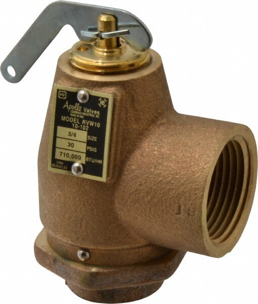
www.apollovalves.com 5 10-408 10-418 10 Series Brass/bronze safety relief valves protect ASME Section IV hot water heating boilers and hydronic heating systems. High capacity design features corrosion resistant construction. Brass, satin or polished chrome finishes available. ASME Section IV Inlet Size 3/4" - Outlet - 3/4” & 1" Set Pressure 20-150 psi Maximum temperature service: 250°F Applications: Ideal for use with hot water boilers and hydronic heating systems. Features • Pressures from 20 to 150 psig • Registered in all Canadian provinces and territories, CRN #0G8547.5C • Stainless...
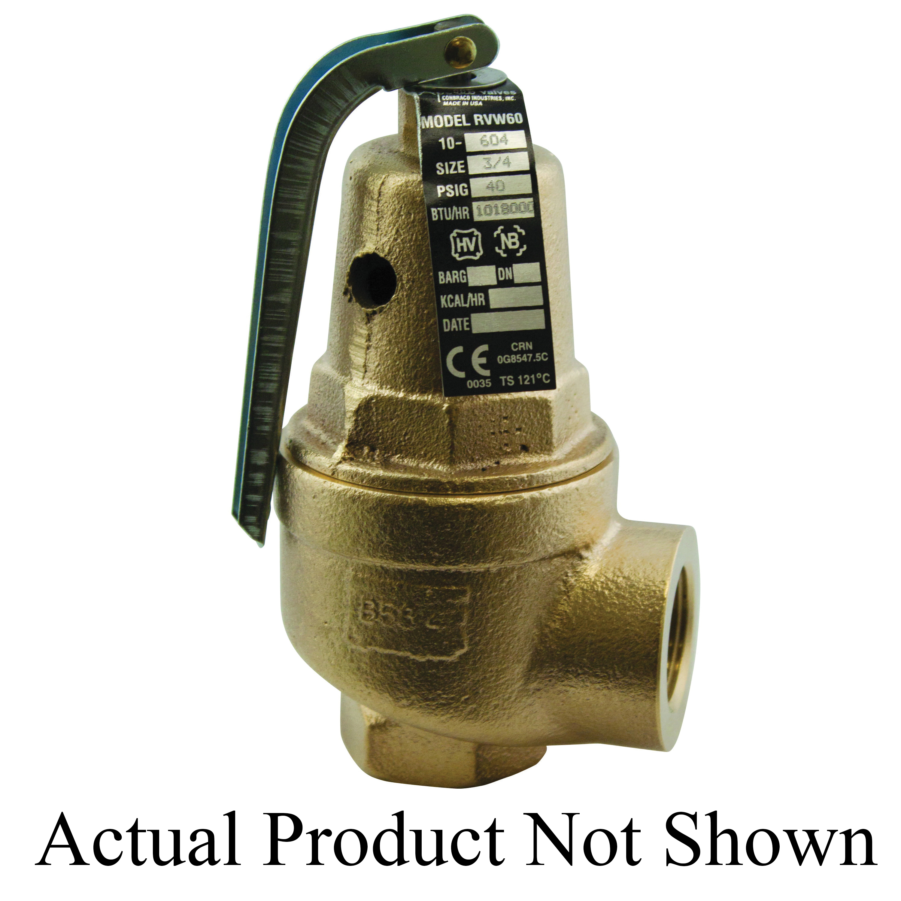
www.apollovalves.com 7 Section VIII Pressure Vessels National Board capacity-certified safety valves; brass body with optional satin or polished chrome finish. Protects against excess pressure from thermal expansion and steam caused by failure of Btu input controls. ASME Section VIII Sizes 1/2" and 3/4" Set pressures 15 to 60 psig@312°F max National Board Certified Capacity Applications: Ideally suited for OEM applications such as steam carpet and jewelry cleaners, autoclaves, sterilizers, commercial pressure cookers, steam jacketed kettles, dental equipment, coffee makers and similar...
12 Customer Service 1-704-841-6000 12-200 Series Low Pressure Steam Heating Boiler Safety Valves Medium capacity safety valves protect ASME Section IV low pressure steam heating boilers. Cast bronze, full nozzle design features PTFE faced elastomer soft seating for dependable operation. ASME Section IV Sizes 2, 2-1/2" and 3" Set pressures 5-15 psi Applications: Medium and large commercial and industrial steam heating and processing boilers. Features • All bronze construction • PTFE-coated O-ring seat seal • 3/8" NPT side tapping for drain • Rust-proofed steel spring • Top guided, high...
www.apollovalves.com 13 ASME Section IV bronze safety valves protect small to medium low pressure steam heating boilers. Three design configurations feature top guiding and raised seating area for extended service life. Available top and side discharge models. ASME Section IV Sizes 3/4"-1-1/2" Set pressure 5 to 15 psi Applications: Low pressure steam heating and supply boilers. Features • Flat seat, PTFE faced disc for positive seal • Standard set pressure of 15 psig • Positive drainage of condensate from seat area • No. 13-101 is top outlet discharge • Registered in all Canadian provinces...
Set Pressure psig Suffix 5 -03 6 -04 8 -05 10 -06 12 -07 15 -08 14 Customer Service 1-704-841-6000 ASME Section IV Set pressures from 5 to 15 psig. Sizes 2", 2-1/2" and 3". Applications: The 14 Series is an ASME Section IV high capacity steam safety valve for use with medium and large size commercial and industrial heating boilers. Features • One piece body, all bronze construction • Rust proofed steel spring • Chrome plated seat, PTFE coated disc • PTFE coated EPDM O-ring for positive seal • 3/8" NPT side tapping for drain connection • Valves are capacity certified by the National Board at...
16 Customer Service 1-704-841-6000 Model Size Dimensions(in./mm.) Wt./Ea Number (in./mm.) A B C (lbs./kg.) 14-X05 2 x 2 3 6-1/2 3-1/8 8.4 50M x 50F 76 165 79 3.81 14-X06 2-1/2 x 2-1/2 3-1/2 7-5/8 3-1/2 12.5 65M x 65F 89 194 89 5.7 14-X07 3 x 3 4-1/8 8-3/4 3-7/8 17.0 80M x 80F 105 222 98 7.7 Dimensions and Weights High volume air relief valves designed for low pressure air and gas service. Rugged bronze construction features elastomer soft seating and TFE coated discs for dependable operation. Non-ASME code air and gas service Inlet sizes 2”, 2 1/2” and 3” Set pressures 4 to 22 psig @ 400°F...
www.apollovalves.com 17 Model Size Dimensions(in./mm.) Wt./Ea Number (in./mm.) A B C (lbs./kg.) 14-605 2 x 2 3 6-1/2 3-1/8 8.4 50M x 50F 76 165 79 3.81 14-606 2-1/2 x 2-1/2 3-1/2 7-5/8 3-1/2 11.8 65M x 65F 89 194 89 5.4 14-607 3 x 3 4-1/8 8-3/4 3-7/8 16.3 80M x 80F 105 222 98 7.4 Dimensions and Weights 14-600 14-600 Series Vacuum Relief Valves Model Numbering System 14-600 Series Vacuum Relief Valves EXAMPLES: 14-607-V14 3" Vacuum relief valve set at 14 Hg" Connect vacuum source here B A C 14 6 05 V12 Series Body / Cap Style Inlet Number and Service Connection Relief Pressure 14 6 = Vacuum...
A series of anomalies occurred in the boiler room that evening. The steel compression tank for the hydronic loop flooded, leaving no room for expansion. Water will expand at 3% of its volume when heated from room temperature to 180° F. When the burner fired, the expansion of the water increased the system pressure within the boiler. The malfunctioning operating control did not shut off the burner at the set point which caused the relief valve to open.
The brass relief valve discharge was installed with copper tubing piped solid to a 90° ell on the floor and the tubing further extended to the floor drain. The combination of hot water and steam from the boiler caused the discharge copper tubing to expand, using the relief valve as a fulcrum. The expansion of the copper discharge tubing pressing against the floor was enough to crack the brass relief valve, flooding the boiler room. The damage was not discovered until the next morning, several hours after the leak occurred. Thousands of dollars in damage was sustained and luckily no one was injured.
Each boiler requires some sort of pressure relieving device. They are referred to as either a safety, relief or safety relief valve. While these names are often thought of as interchangeable, there are subtle differences between them. According to the National Board of Boiler and Pressure Vessel Inspectors, the following are the definitions of each:
• Safety valve— This device is typically used for steam or vapor service. It operates automatically with a full-opening pop action and recloses when the pressure drops to a value consistent with the blowdown requirements prescribed by the applicable governing code or standard.
• Relief valve— This device is used for liquid service. It operates automatically by opening farther as the pressure increases beyond the initial opening pressure and recloses when the pressure drops below the opening pressure.
• Safety relief valve— This device includes the operating characteristics of both a safety valve and a relief valve and may be used in either application.
• Temperature and pressure safety relief valve— This device is typically used on potable water heaters. In addition to its pressure-relief function, it also includes a temperature-sensing element which causes the device to open at a predetermined temperature regardless of pressure. The set temperature on these devices is usually 210°.
• Relief valve piping— The boiler contractor installed a bushing on the outlet of the safety relief valve. Instead of 1 1/2-in. pipe, the installer used 3/4-in. pipe. When asked about it, he answered that he did not have any 1 1/2-in. pipe but had plenty of 3/4-in. pipe. I explained and then had to show the disbelieving contractor the code that states that the relief valve discharge piping has to be the same diameter as the relief valve outlet (see 2012 International Mechanical Code, 1006.6). By reducing the discharge pipe size, the relieving capacity of the safety valve may not be adequate to properly relieve the pressure inside the boiler, causing a dangerous situation.
The code also states that the discharge material shall be of rigid pipe that is approved for the temperature of the system. The inlet pipe size shall be full diameter of the pipe inlet for the relief valve. Some manufacturers suggest using black iron pipe rather than copper tubing. If using copper, it should have an air space that allows expansion should the relief valve open to avoid the accident that I referenced above. The discharge piping has to be supported and the weight of the piping should not be on the safety relief valve. Valves are not permitted in the inlet piping to or discharge piping from the relief valve. If you are using copper tubing on discharge piping, verify that there is room for expansion.
• Installation— Read the manufacturer’s installation manual as each may have different requirements. For instance, Conbraco requires that the discharge piping must terminate with a plain end and use a material that can handle temperatures of 375° or greater. This will preclude PVC or CPVC pipe for the discharge piping. The instruction manual for its model 12-14 steam relief valve stipulates that you cannot use a pipe wrench to install it. That would be good to know.
I once visited Boiler Utopia as the floor was clean and waxed. All the pipes were covered and exposed pipes were painted. There were large stickers detailing what was inside each pipe as well as directional arrows. Nothing was stacked next to the boilers. Yellow caution lines were painted on the floor around each boiler. I was in heaven. As I walked around the rear of the boiler, something clicked and triggered a warning bell. The discharge of the relief valve piping was about 6 in. from the floor but instead of a plain or angled cut end, the pipe had a threaded pipe cap on the termination. I asked the maintenance person about it and he said that the valve was leaking all over his newly waxed floor and this was the only way he could stop it. When I said that the discharge pipe should not have been threaded, he explained that it was not threaded and he had to take it to the local hardware store to thread it. I informed him that the cap had to be removed. We cut the pipe on an angle to prevent this.
• Steam boiler— Most manufacturers recommend a drip pan ell on the discharge of the steam boiler relief valve to eliminate the weight of the discharge piping on the relief valve. Some codes require the discharge to be vented outdoors.
• Testing— I will ask the attendees in my classes, “How often do you test the relief valves?” Most do not make eye contact and when I follow up with, “Why are they not tested?” I often hear that opening the relief valve will cause it to leak. I suggest that you refer to each manufacturer’s directions for testing. For instance, one will recommend once a year while another recommends twice a year. One manufacturer says, “Safety/relief valves should be operated only often enough to assure they are in good working order.” I am not sure what that even means. You want to also verify the proper test procedure as some will only want the relief valve tested when the boiler is at 75% of the rated pressure or higher of the relief valve.

The primary purpose of a pressure relief valve is to protect life, property and the environment. Pressure relief valves are designed to open and release excess pressure from vessels or equipment and then close again.
The function of pressure relief valves differs depending on the main type or loading principle of the valve. The main types of pressure relief valves are spring-loaded, weight-loaded and controlled pressure relief valves.
Regardless of the type or load, pressure relief valves are set to a specific set pressure at which the medium is discharged in a controlled manner, thus preventing overpressure of the equipment. In dependence of several parameters such as the contained medium, the set pressure is individual for each safety application.

Your pressure relief valve is making a strange noise, and you’re worried about potential damages to the surrounding pipes and valves. When you hear moaning noises coming from a valve, or even sounds like sputtering, vibrations, or hissing noises coming from your pressure relief valve, it can be a cause for alarm. You’ll want to find the root cause of your noisy valve as soon as possible, and we’re here to help.
There are many reasons why your pressure relief valve is making noises. In some cases, these noises can be a sign your pressure valve is bad. In order to help you diagnose the problem, let’s divide the causes into the following three categories of valve noises: mechanical vibration noise, fluid dynamics noise, and aerodynamics noise. Now, let’s take a closer look at each of these causes of noises from sanitary pressure relief valves.
Various parts of pressure relief valves produce mechanical vibrations when fluid flows through them. Usually, this vibration is not noticeable, but it can become a nuisance when maintenance is required. These mechanical vibrations can be divided into two types:
Low-frequency vibrations are caused by jets and pulsations in the fluid medium brought on by fast flow rates at the valve outlet, unreasonable or inefficient pipeline layouts, and insufficient stiffness of the active parts of the valve.
High-frequency vibrations create resonance when the natural frequency of the valve coincides with the excitation frequency caused by the fluid flow. This phenomenon occurs within a certain range of pressure-reducing sanitary pressure relief valves. And the changes in noise can be very large once there’s even the slightest change in conditions. This kind of mechanical vibration noise has nothing to do with the flow rate of the medium but is primarily due to the unreasonable design of the pressure relief valve.
Fluid dynamics can generate noise from turbulence and eddy currents after the fluid passes through the valve’s pressure-reducing port. The process can be divided into two stages:
Turbulence noise is generated by the interactions between the turbulent fluid and the pressure relief valve or pipe surface. Its frequency and noise level are relatively low, which generally does not constitute a noise problem. If it does become a noise issue, you may need to rearrange the pipeline more efficiently.
During the valve’s pressure-reducing process, the fluid (liquid) will begin to vaporize once the fluid flow rate reaches a particular value. When the pressure on the bubble inside the liquid reaches a specific level, the bubble will explode, leading to very high pressure and shock waves in some parts. The instant pressure of the impact can be up to 196MPa. The pressure will sharply decline in locations far away from the center of the explosion. Shock waves can be a major factor in cavitation noises coming from the pressure relief valve.
When vapor and other compressible fluid pass through the pressure-reducing portion of the pressure relief valve, the fluid’s mechanical energy is converted into sound energy, and the water regulator produces an audible nuisance.
While these are the most common causes of noisy valves, there are several more possibilities. In rare cases, a failed expansion tank, quick closing pressure relief valves on new appliances, bad vacuum breakers, faulty valves with loose washers, or even improperly strapped pipes can be the cause of those noises coming from your pressure relief valve. In addition to the noises, also check for the signs that your pressure valve is bad.
First, check for a specified replacement cycle on the valve itself. If there is no date listed, you can also check the manufacturer’s website or contact them directly. If you still can’t find the specified replacement life cycle, you should replace most pressure relief valves five years after the manufacture date. Many industries recommend replacing relief valves on a five-year schedule.


 8613371530291