
conventional safety valve in stock

There is a wide range of safety valves available to meet the many different applications and performance criteria demanded by different industries. Furthermore, national standards define many varying types of safety valve.
The ASME standard I and ASME standard VIII for boiler and pressure vessel applications and the ASME/ANSI PTC 25.3 standard for safety valves and relief valves provide the following definition. These standards set performance characteristics as well as defining the different types of safety valves that are used:
ASME I valve - A safety relief valve conforming to the requirements of Section I of the ASME pressure vessel code for boiler applications which will open within 3% overpressure and close within 4%. It will usually feature two blowdown rings, and is identified by a National Board ‘V’ stamp.
ASME VIII valve- A safety relief valve conforming to the requirements of Section VIII of the ASME pressure vessel code for pressure vessel applications which will open within 10% overpressure and close within 7%. Identified by a National Board ‘UV’ stamp.
Full bore safety valve - A safety valve having no protrusions in the bore, and wherein the valve lifts to an extent sufficient for the minimum area at any section, at or below the seat, to become the controlling orifice.
Conventional safety relief valve -The spring housing is vented to the discharge side, hence operational characteristics are directly affected by changes in the backpressure to the valve.
Balanced safety relief valve -A balanced valve incorporates a means of minimising the effect of backpressure on the operational characteristics of the valve.
Pilot operated pressure relief valve -The major relieving device is combined with, and is controlled by, a self-actuated auxiliary pressure relief device.
Power-actuated safety relief valve - A pressure relief valve in which the major pressure relieving device is combined with, and controlled by, a device requiring an external source of energy.
Standard safety valve - A valve which, following opening, reaches the degree of lift necessary for the mass flowrate to be discharged within a pressure rise of not more than 10%. (The valve is characterised by a pop type action and is sometimes known as high lift).
Full lift (Vollhub) safety valve -A safety valve which, after commencement of lift, opens rapidly within a 5% pressure rise up to the full lift as limited by the design. The amount of lift up to the rapid opening (proportional range) shall not be more than 20%.
Direct loaded safety valve -A safety valve in which the opening force underneath the valve disc is opposed by a closing force such as a spring or a weight.
Proportional safety valve - A safety valve which opens more or less steadily in relation to the increase in pressure. Sudden opening within a 10% lift range will not occur without pressure increase. Following opening within a pressure of not more than 10%, these safety valves achieve the lift necessary for the mass flow to be discharged.
Diaphragm safety valve -A direct loaded safety valve wherein linear moving and rotating elements and springs are protected against the effects of the fluid by a diaphragm
Bellows safety valve - A direct loaded safety valve wherein sliding and (partially or fully) rotating elements and springs are protected against the effects of the fluids by a bellows. The bellows may be of such a design that it compensates for influences of backpressure.
Controlled safety valve - Consists of a main valve and a control device. It also includes direct acting safety valves with supplementary loading in which, until the set pressure is reached, an additional force increases the closing force.
Safety valve - A safety valve which automatically, without the assistance of any energy other than that of the fluid concerned, discharges a quantity of the fluid so as to prevent a predetermined safe pressure being exceeded, and which is designed to re-close and prevent further flow of fluid after normal pressure conditions of service have been restored. Note; the valve can be characterised either by pop action (rapid opening) or by opening in proportion (not necessarily linear) to the increase in pressure over the set pressure.
Direct loaded safety valve -A safety valve in which the loading due to the fluid pressure underneath the valve disc is opposed only by a direct mechanical loading device such as a weight, lever and weight, or a spring.
Assisted safety valve -A safety valve which by means of a powered assistance mechanism, may additionally be lifted at a pressure lower than the set pressure and will, even in the event of a failure of the assistance mechanism, comply with all the requirements for safety valves given in the standard.
Supplementary loaded safety valve - A safety valve that has, until the pressure at the inlet to the safety valve reaches the set pressure, an additional force, which increases the sealing force.
Note; this additional force (supplementary load), which may be provided by means of an extraneous power source, is reliably released when the pressure at the inlet of the safety valve reaches the set pressure. The amount of supplementary loading is so arranged that if such supplementary loading is not released, the safety valve will attain its certified discharge capacity at a pressure not greater than 1.1 times the maximum allowable pressure of the equipment to be protected.
Pilot operated safety valve -A safety valve, the operation of which is initiated and controlled by the fluid discharged from a pilot valve, which is itself, a direct loaded safety valve subject to the requirement of the standard.
The common characteristic shared between the definitions of conventional safety valves in the different standards, is that their operational characteristics are affected by any backpressure in the discharge system. It is important to note that the total backpressure is generated from two components; superimposed backpressure and the built-up backpressure:
Subsequently, in a conventional safety valve, only the superimposed backpressure will affect the opening characteristic and set value, but the combined backpressure will alter the blowdown characteristic and re-seat value.
The ASME/ANSI standard makes the further classification that conventional valves have a spring housing that is vented to the discharge side of the valve. If the spring housing is vented to the atmosphere, any superimposed backpressure will still affect the operational characteristics. Thiscan be seen from Figure 9.2.1, which shows schematic diagrams of valves whose spring housings are vented to the discharge side of the valve and to the atmosphere.
By considering the forces acting on the disc (with area AD), it can be seen that the required opening force (equivalent to the product of inlet pressure (PV) and the nozzle area (AN)) is the sum of the spring force (FS) and the force due to the backpressure (PB) acting on the top and bottom of the disc. In the case of a spring housing vented to the discharge side of the valve (an ASME conventional safety relief valve, see Figure 9.2.1 (a)), the required opening force is:
In both cases, if a significant superimposed backpressure exists, its effects on the set pressure need to be considered when designing a safety valve system.
Once the valve starts to open, the effects of built-up backpressure also have to be taken into account. For a conventional safety valve with the spring housing vented to the discharge side of the valve, see Figure 9.2.1 (a), the effect of built-up backpressure can be determined by considering Equation 9.2.1 and by noting that once the valve starts to open, the inlet pressure is the sum of the set pressure, PS, and the overpressure, PO.
Balanced safety valves are those that incorporate a means of eliminating the effects of backpressure. There are two basic designs that can be used to achieve this:
Although there are several variations of the piston valve, they generally consist of a piston type disc whose movement is constrained by a vented guide. The area of the top face of the piston, AP, and the nozzle seat area, AN, are designed to be equal. This means that the effective area of both the top and bottom surfaces of the disc exposed to the backpressure are equal, and therefore any additional forces are balanced. In addition, the spring bonnet is vented such that the top face of the piston is subjected to atmospheric pressure, as shown in Figure 9.2.2.
The bellows arrangement prevents backpressure acting on the upper side of the disc within the area of the bellows. The disc area extending beyond the bellows and the opposing disc area are equal, and so the forces acting on the disc are balanced, and the backpressure has little effect on the valve opening pressure.
Bellows failure is an important concern when using a bellows balanced safety valve, as this may affect the set pressure and capacity of the valve. It is important, therefore, that there is some mechanism for detecting any uncharacteristic fluid flow through the bellows vents. In addition, some bellows balanced safety valves include an auxiliary piston that is used to overcome the effects of backpressure in the case of bellows failure. This type of safety valve is usually only used on critical applications in the oil and petrochemical industries.
Since balanced pressure relief valves are typically more expensive than their unbalanced counterparts, they are commonly only used where high pressure manifolds are unavoidable, or in critical applications where a very precise set pressure or blowdown is required.
This type of safety valve uses the flowing medium itself, through a pilot valve, to apply the closing force on the safety valve disc. The pilot valve is itself a small safety valve.
The diaphragm type is typically only available for low pressure applications and it produces a proportional type action, characteristic of relief valves used in liquid systems. They are therefore of little use in steam systems, consequently, they will not be considered in this text.
The piston type valve consists of a main valve, which uses a piston shaped closing device (or obturator), and an external pilot valve. Figure 9.2.4 shows a diagram of a typical piston type, pilot operated safety valve.
The piston and seating arrangement incorporated in the main valve is designed so that the bottom area of the piston, exposed to the inlet fluid, is less than the area of the top of the piston. As both ends of the piston are exposed to the fluid at the same pressure, this means that under normal system operating conditions, the closing force, resulting from the larger top area, is greater than the inlet force. The resultant downward force therefore holds the piston firmly on its seat.
If the inlet pressure were to rise, the net closing force on the piston also increases, ensuring that a tight shut-off is continually maintained. However, when the inlet pressure reaches the set pressure, the pilot valve will pop open to release the fluid pressure above the piston. With much less fluid pressure acting on the upper surface of the piston, the inlet pressure generates a net upwards force and the piston will leave its seat. This causes the main valve to pop open, allowing the process fluid to be discharged.
When the inlet pressure has been sufficiently reduced, the pilot valve will reclose, preventing the further release of fluid from the top of the piston, thereby re-establishing the net downward force, and causing the piston to reseat.
Pilot operated safety valves offer good overpressure and blowdown performance (a blowdown of 2% is attainable). For this reason, they are used where a narrow margin is required between the set pressure and the system operating pressure. Pilot operated valves are also available in much larger sizes, making them the preferred type of safety valve for larger capacities.
One of the main concerns with pilot operated safety valves is that the small bore, pilot connecting pipes are susceptible to blockage by foreign matter, or due to the collection of condensate in these pipes. This can lead to the failure of the valve, either in the open or closed position, depending on where the blockage occurs.
The terms full lift, high lift and low lift refer to the amount of travel the disc undergoes as it moves from its closed position to the position required to produce the certified discharge capacity, and how this affects the discharge capacity of the valve.
A full lift safety valve is one in which the disc lifts sufficiently, so that the curtain area no longer influences the discharge area. The discharge area, and therefore the capacity of the valve are subsequently determined by the bore area. This occurs when the disc lifts a distance of at least a quarter of the bore diameter. A full lift conventional safety valve is often the best choice for general steam applications.
The disc of a high lift safety valve lifts a distance of at least 1/12th of the bore diameter. This means that the curtain area, and ultimately the position of the disc, determines the discharge area. The discharge capacities of high lift valves tend to be significantly lower than those of full lift valves, and for a given discharge capacity, it is usually possible to select a full lift valve that has a nominal size several times smaller than a corresponding high lift valve, which usually incurs cost advantages.Furthermore, high lift valves tend to be used on compressible fluids where their action is more proportional.
In low lift valves, the disc only lifts a distance of 1/24th of the bore diameter. The discharge area is determined entirely by the position of the disc, and since the disc only lifts a small amount, the capacities tend to be much lower than those of full or high lift valves.
Except when safety valves are discharging, the only parts that are wetted by the process fluid are the inlet tract (nozzle) and the disc. Since safety valves operate infrequently under normal conditions, all other components can be manufactured from standard materials for most applications. There are however several exceptions, in which case, special materials have to be used, these include:
Cast steel -Commonly used on higher pressure valves (up to 40 bar g). Process type valves are usually made from a cast steel body with an austenitic full nozzle type construction.
For all safety valves, it is important that moving parts, particularly the spindle and guides are made from materials that will not easily degrade or corrode. As seats and discs are constantly in contact with the process fluid, they must be able to resist the effects of erosion and corrosion.
The spring is a critical element of the safety valve and must provide reliable performance within the required parameters. Standard safety valves will typically use carbon steel for moderate temperatures. Tungsten steel is used for higher temperature, non-corrosive applications, and stainless steel is used for corrosive or clean steam duty. For sour gas and high temperature applications, often special materials such as monel, hastelloy and ‘inconel’ are used.
Standard safety valves are generally fitted with an easing lever, which enables the valve to be lifted manually in order to ensure that it is operational at pressures in excess of 75% of set pressure. This is usually done as part of routine safety checks, or during maintenance to prevent seizing. The fitting of a lever is usually a requirement of national standards and insurance companies for steam and hot water applications. For example, the ASME Boiler and Pressure Vessel Code states that pressure relief valves must be fitted with a lever if they are to be used on air, water over 60°C, and steam.
A test gag (Figure 9.2.7) may be used to prevent the valve from opening at the set pressure during hydraulic testing when commissioning a system. Once tested, the gag screw is removed and replaced with a short blanking plug before the valve is placed in service.
The amount of fluid depends on the particular design of safety valve. If emission of this fluid into the atmosphere is acceptable, the spring housing may be vented to the atmosphere – an open bonnet. This is usually advantageous when the safety valve is used on high temperature fluids or for boiler applications as, otherwise, high temperatures can relax the spring, altering the set pressure of the valve. However, using an open bonnet exposes the valve spring and internals to environmental conditions, which can lead to damage and corrosion of the spring.
When the fluid must be completely contained by the safety valve (and the discharge system), it is necessary to use a closed bonnet, which is not vented to the atmosphere. This type of spring enclosure is almost universally used for small screwed valves and, it is becoming increasingly common on many valve ranges since, particularly on steam, discharge of the fluid could be hazardous to personnel.
Some safety valves, most commonly those used for water applications, incorporate a flexible diaphragm or bellows to isolate the safety valve spring and upper chamber from the process fluid, (see Figure 9.2.9).

Curtiss-Wright"s selection of Pressure Relief Valves comes from its outstanding product brands Farris and Target Rock. We endeavor to support the whole life cycle of a facility and continuously provide custom products and technologies. Boasting a reputation for producing high quality, durable products, our collection of Pressure Relief Valves is guaranteed to provide effective and reliable pressure relief.
While some basic components and activations in relieving pressure may differ between the specific types of relief valves, each aims to be 100% effective in keeping your equipment running safely. Our current range includes numerous valve types, from flanged to spring-loaded, threaded to wireless, pilot operated, and much more.
A pressure relief valve is a type of safety valve designed to control the pressure in a vessel. It protects the system and keeps the people operating the device safely in an overpressure event or equipment failure.
A pressure relief valve is designed to withstand a maximum allowable working pressure (MAWP). Once an overpressure event occurs in the system, the pressure relief valve detects pressure beyond its design"s specified capability. The pressure relief valve would then discharge the pressurized fluid or gas to flow from an auxiliary passage out of the system.
Below is an example of one of our pilot operated pressure relief valves in action; the cutaway demonstrates when high pressure is released from the system.
Air pressure relief valves can be applied to a variety of environments and equipment. Pressure relief valves are a safety valve used to keep equipment and the operators safe too. They"re instrumental in applications where proper pressure levels are vital for correct and safe operation. Such as oil and gas, power generation like central heating systems, and multi-phase applications in refining and chemical processing.
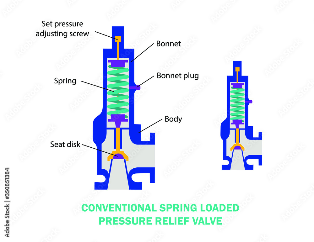
At Curtiss-Wright, we provide a range of different pressure relief valves based on two primary operations – spring-loaded and pilot operated. Spring-loaded valves can either be conventional spring-loaded or balanced spring-loaded.
Spring-loaded valves are programmed to open and close via a spring mechanism. They open when the pressure reaches an unacceptable level to release the material inside the vessel. It closes automatically when the pressure is released, and it returns to an average operating level. Spring-loaded safety valves rely on the closing force applied by a spring onto the main seating area. They can also be controlled in numerous ways, such as a remote, control panel, and computer program.
Pilot-operated relief valves operate by combining the primary relieving device (main valve) with self-actuated auxiliary pressure relief valves, also known as the pilot control. This pilot control dictates the opening and closing of the main valve and responds to system pressure. System pressure is fed from the inlet into and through the pilot control and ultimately into the main valve"s dome. In normal operating conditions, system pressure will prevent the main valve from opening.
The valves allow media to flow from an auxiliary passage and out of the system once absolute pressure is reached, whether it is a maximum or minimum level.
When the pressure is below the maximum amount, the pressure differential is slightly positive on the piston"s dome size, which keeps the main valve in the closed position. When system pressure rises and reaches the set point, the pilot will cut off flow to the dome, causing depressurization in the piston"s dome side. The pressure differential has reversed, and the piston will rise, opening the main valve, relieving pressure.
When the process pressure decreases to a specific pressure, the pilot closes, the dome is repressurized, and the main valve closes. The main difference between spring-loaded PRVs and pilot-operated is that a pilot-operated safety valve uses pressure to keep the valve closed.
Pilot-operated relief valves are controlled by hand and are typically opened often through a wheel or similar component. The user opens the valve when the gauge signifies that the system pressure is at an unsafe level; once the valve has opened and the pressure has been released, the operator can shut it by hand again.
Increasing pressure helps to maintain the pilot"s seal. Once the setpoint has been reached, the valve opens. This reduces leakage and fugitive emissions.
At set pressure the valve snaps to full lift. This can be quite violent on large pipes with significant pressure. The pressure has to drop below the set pressure in order for the piston to reseat.
At Curtiss-Wright we also provide solutions for pressure relief valve monitoring. Historically, pressure relief valves have been difficult or impossible to monitor. Our SmartPRV features a 2600 Series pressure relief valve accessorized with a wireless position monitor that alerts plant operators during an overpressure event, including the time and duration.
There are many causes of overpressure, but the most common ones are typically blocked discharge in the system, gas blowby, and fire. Even proper inspection and maintenance will not eliminate the occurrence of leakages. An air pressure relief valve is the only way to ensure a safe environment for the device, its surroundings, and operators.
A PRV and PSV are interchangeable, but there is a difference between the two valves. A pressure release valve gradually opens when experiencing pressure, whereas a pressure safety valve opens suddenly when the pressure hits a certain level of over pressurization. Safety valves can be used manually and are typically used for a permanent shutdown. Air pressure relief valves are used for operational requirements, and they gently release the pressure before it hits the maximum high-pressure point and circulates it back into the system.
Pressure relief valves should be subject to an annual test, one per year. The operator is responsible for carrying out the test, which should be done using an air compressor. It’s imperative to ensure pressure relief valves maintain their effectiveness over time and are checked for signs of corrosion and loss of functionality. Air pressure relief valves should also be checked before their installation, after each fire event, and regularly as decided by the operators.
Direct-acting solenoid valves have a direct connection with the opening and closing armature, whereas pilot-operated valves use of the process fluid to assist in piloting the operation of the valve.
A control valve works by varying the rate of fluid passing through the valve itself. As the valve stem moves, it alters the size of the passage and increases, decreases or holds steady the flow. The opening and closing of the valve is altered whenever the controlled process parameter does not reach the set point.
Control valves are usually at floor level or easily accessible via platforms. They are also located on the same equipment or pipeline as the measurement and downstream or flow measurements.
An industrial relief valve is designed to control or limit surges of pressure in a system, most often in fluid or compressed air system valves. It does so as a form of protection for the system and defending against instrument or equipment failure. They are usually present in clean water industries.
A PRV is often referred to as a pressure relief valve, which is also known as a PSV or pressure safety valve. They are used interchangeably throughout the industry depending on company standards.

Industry leading pressure and safety relief valve designs with over 140 years of technical and application expertise providing custom engineered solutions for O&G, Refining, Chemical, Petrochemical, Process and Power applications. Our designs meet global and local codes and standards (API 526; ASME Section I, IV & VIII; EN ISO 4126; PED & more). Gain insight into the performance of your pressure relief valves with wireless monitoring.
A pressure safety valve actuated by inlet static pressure and characterized by rapid opening or rapid popping action. This safety valve is tight shut-off and is for safety only. Meets ASME SEC. VIII (Not a Fulflo valve)
A spring loaded pressure relief valve, actuated by the static pressure upstream of the valve. The valve opens normally in proportion to the increase in pressure over the set pressure. (Fulflo)
A pressure relief valve characterized by rapid opening or pop-action in direct proportion to the pressure increase, depending on the application. (Fulflo)
The pressure existing at the outlet of a pressure relief valve, due to the pressure in the discharge system. The pressure can be constant or variable. It is the sum of the superimposed and build-up pressure.
Fulflo was established in 1912 and is celebrating its 100th anniversary. Located in Blanchester, OH, Fulflo was incorporated in 1933 under its present name and trademark. Patents for the original guided piston, direct acting relief valve were obtained in 1935, coinciding with the onset of fluid power systems. The need for providing large flows without excessive bulk was met by the pilot-valve-control relief valve which was patented in 1943.
Fulflo parts and valves are used in oil and gas refineries, are essential to the military, including ships and aircraft carriers, and amusement roller coaster rides.
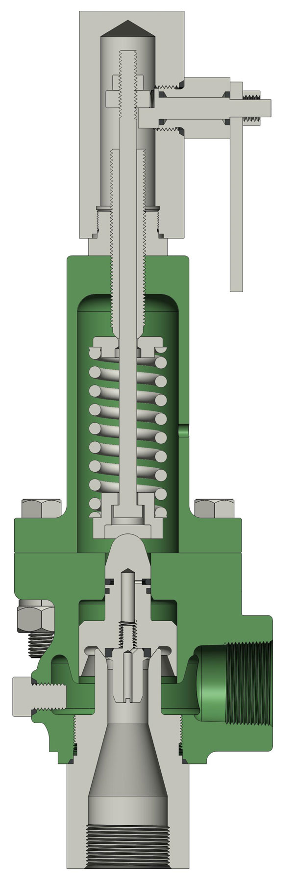
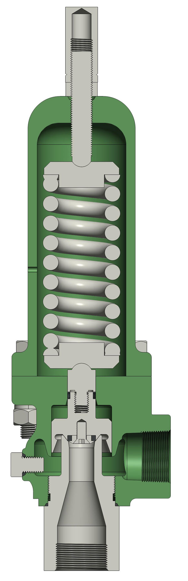
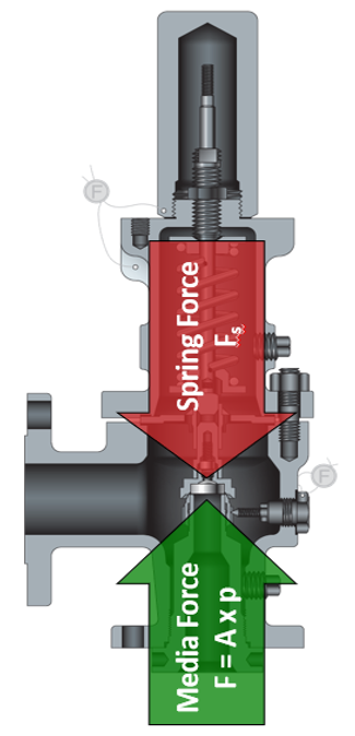
A conventional valve uses a spring to keep the valve closed until the process nears the set pressure. The spring force pushes the valve’s disc against the nozzle seat keeping the valve closed. Process pressure exerts an opposing force on the disc. When the process pressure force on the disc overcomes the opposing spring force, the disc lifts and the valve begins to relieve pressure.
In contrast, a pilot operated valveuses process pressure to keep the valve closed until set pressure is reached. PORVs include a main valve that relieves the required capacity of process media and a pilot valve that controls the main valve. Until set pressure is reached, both the top and bottom of the valve’s piston are exposed to process pressure forces. The surface area on top of the piston is larger than the surface area of the bottom of the piston at the nozzle.
The force atop the piston is greater than the force on the piston at the nozzle because of the difference in area and pressure being equal. As a result, as process pressure increases, the sealing force of the piston increases as well. When set pressure is reached, the pilot valve relieves the pressurized fluid from the dome area atop the piston. This allows the process pressure at the nozzle to force the piston upward from its seat, allowing the valve to relieve system pressure.
Conventional relief valves can be the best fit for applications that will expose the valve to high temperatures, highly viscous, or dirty services. In smaller sizes they are generally lower cost than PORVs, and most designs will follow standard API 526 center-to-face flange dimensions.
Conventional PRVs may not be well suited for applications requiring maximum seat tightness / sealing, minimal simmer, or applications with high or variable back pressures. Measures can be taken to mitigate these shortcomings; however they bring limitations of their own.
For example, a conventional valve can be constructed with a soft seat to improve sealing, but this will generally introduce temperature limitations. To reduce the effects of back pressure a conventional PRV can be outfitted with a bellows. However, a bellows has lower back pressure tolerance than a PORV and can be more costly to maintain.
The PORV is designed to mitigate many shortcomings of a conventional valve but has its own limitations. PORVs are well suited to many applications, including:
However, PORVs’ suitability is limited in high temperature applications, as their construction typically includes several soft seals. Due to the small flow paths in the pilot valve and tubing, PORVs may not be a good fit for highly viscous process medias or those containing high levels of particulate. In smaller sizes, PORVs are typically higher cost than conventional valves but can offer significant cost savings in larger sizes.
There are several configurations available for both conventional and pilot operated pressure relief valves. Each application should be considered carefully when selecting and specifying a pressure relief valve. AWC’s team of trusted resources is here to assist with application review, selection, sizing, training, maintenance, and asset life cycle management. Our goal is to help ensure a safe, successful installation over the lifetime of the valve.
![]()
Safety relief valves often serve as the point-of-protection against potentially dangerous circumstances, so it is important that they be dependable. Baker Hughes provides various valve styles, sizes, options and configurations for multiple industries and applications.
Baker Hughes continues to pursue quality and pro-active approach through regular collaboration with our customers and by staying actively involved in the development of regulatory compliance standards. We configure, engineer, and manufacture safety relief valves that adhere to industry regulations and global and regional standards while helping meet our customers’ evolving needs.
Not sure which valve you need for your application?Download ValSpeQ (Mooney regulators & Becker valves) or ValvStream™ (Masoneilan and Consolidated valves) to size, select and generate proposal documentation for your valves.
Consolidated Green Tag Centers (GTC) from Baker Hughes Energy comprise one of the broadest OEM service networks in the industry. With more than 80 facilities located in more than 30 countries worldwide, the GTCNet™ network provides the aftermarket support you need. Our GTC customers receive responsive and effective service through OEM-certified repairs, innovative valve diagnostics from ValvKeep™- valve management and maintenance software, and the EVT-Pro, an electronic valve testing device. Each GTC location is staffed with highly qualified technicians, specifically trained and certified to deliver exceptional product support and technical expertise.
![]()
The primary purpose of a safety valve is to protect life, property and the environment. Safety valves are designed to open and release excess pressure from vessels or equipment and then close again.
The function of safety valves differs depending on the load or main type of the valve. The main types of safety valves are spring-loaded, weight-loaded and controlled safety valves.
Regardless of the type or load, safety valves are set to a specific set pressure at which the medium is discharged in a controlled manner, thus preventing overpressure of the equipment. In dependence of several parameters such as the contained medium, the set pressure is individual for each safety application.

In the United States, use of such devices was spurred by the 1,700 boiler explosions that resulted in 1,300 deaths from 1905 to 1911. By 1915, the American Society of Mechanical Engineers (ASME) published its first boiler code, Rules for Construction of Stationary Boilers and Allowable Working Pressures, incorporating rules for construction and installation of safety valves for boilers.
The primary purpose of a pressure relief valve is to open to relieve excess pressure, reclose and prevent further flow of fluid after normal conditions have been restored (Figure 5). A secondary purpose is to minimize damage to other system components through operation of the pressure relief valve itself. A pressure relief valve designed under ASME Boiler and Pressure Vessel Code is stamped with the certification mark, and one of the certification designators: V, NV, HV, UV, UV3 or TV.
The many types of pressure relief valves that exist are based on different designs and construction. Generally, they’re classified as: safety relief valves, relief valves and safety valves.
A conventional safety relief valve is a spring-loaded pressure relief valve characterized by a rapid-opening pop action. Conventional safety relief valves are used for applications where excessive variable or built-up back pressure is not present in the system. The operational characteristics of these valves are directly affected by changes in the back pressure on the valve.
The working principle of a conventional spring-loaded safety relief valve is based on the balance of force. The spring load is preset to equal the force the inlet fluid exerts on the closed disk when the system pressure is at the set pressure of the valve.
The disk remains seated on the nozzle in the closed position when the inlet pressure is below the set pressure. The valve opens when the inlet pressure exceeds set pressure, overcoming the spring force. The valve recloses when the inlet pressure is reduced to a level below the set pressure.
Once the valve has opened, an additional pressure buildup at C occurs. This additional force at C causes the disk to lift substantially at pop. The valve closes when the inlet pressure has dropped sufficiently below the set pressure. The pressure at which the valve resets is called the closing pressure. The difference between the set pressure and closing pressure is the blowdown.
In the design of a conventional valve, an important consideration is seat leakage. This leakage can result in continuous loss of system fluid and may cause progressive damage to the valve seating surface. Based on the seating material, conventional valves are classified as:
Metal-seated valves. Metal-to-metal seats are commonly made from stainless or other hard alloy steels and are normally used for high-temperature applications such as steam and corrosive media applications for processing a wide variety of chemicals.
Soft-seated valve. An alternative to metal is resilient disks that can be fixed to either or both the seating surfaces where tighter shut-off is required. They are common for gas or liquid applications. These inserts may be made from a number of different materials, but Vinton, nitrile or EPDM (ethylene propylene diene monomer) are the most common.
Balanced bellows with auxiliary balancing piston. With this valve, the balanced bellows seal the body and fluid stream from the bonnet and working parts. The auxiliary balancing piston assures proper valve performance by compensating for back pressure in case the bellows fail.
The primary difference between a pilot-operated safety relief valve and a spring-loaded pressure relief valve is that the pilot-operated valve uses process pressure to keep the valve closed instead of a spring. A pilot is used to sense process pressure and to pressurize or vent the dome pressure chamber, which controls the valve opening or closing.
A pilot-operated safety relief valve consists of the main valve, a floating, unbalanced piston assembly, and an external pilot. The pilot controls the pressure on the top side of the main valve’s unbalanced moving chamber. A resilient seat is normally attached to the lower end.
At below-set level, the pressure on opposite sides of the moving member is equal. When the set pressure is reached, the pilot opens and depressurizes the cavity on the top side so the unbalanced member moves upward, causing the main valve to relieve. When the process pressure decreases to a predetermined pressure, the pilot closes, the cavity above the piston is depressurized and the main valve closes.
The valves operate bubble tight at higher operating pressure-to-set pressure ratios, allowing operators to run very close to the vessel’s maximum allowable working pressure.
Valve movement to open or close is fully controlled by a source of power such as electricity, steam or water (hydraulic). The valve may discharge to the atmosphere or to a container that is at lower pressure. The discharge capacity can be affected by downstream conditions.
Power-actuated safety relief valves are used mostly for forced-flow steam generators with no fixed steam or waterline. They are also used in nuclear power plants.
A temperature and pressure-actuated safety relief valve (also called a T&P safety relief valve) is a pressure relief valve that may be actuated by temperature or pressure on the inlet side (Figure 10).
Such a valve is designed for dual purposes. First, the T&P valve prevents temperature within a vessel from rising above a specified limit (generally 210°F or 98°C). Second, the T&P valve prevents pressure in the vessel from rising above a specified value.
A relief valve is actuated by inlet static pressure and a gradual lift that is generally proportional to the increase in pressure over opening pressure. Such a valve can be provided with enclosed spring housing suitable for closed discharge system applications.
Relief valves are commonly used in liquid systems, especially for lower capacities and thermal expansion applications. They also can be used on pump systems.
Adjustable relief valves feature convenient adjustment of the pressure setting through the outlet port. They are suitable for non-vented or vented inline applications in chemical, petrochemical and high-purity gas industries.
Electronic relief valves (ERVs) are pilot-operated relief valves that offer zero leakage. The ERV package combines a zero-leakage isolation valve with electric controls to monitor and regulate system pressure. These valves provide protection either in a capacity-relieving function or simply in an overpressure-protection application.
Safety valves are typically used for boiler overpressure protection and other applications such as downstream from pressure-reducing controls. These valves are installed wherever the maximum allowable working pressure of boilers is likely to be exceeded. Safety valves are also used for compressible gases, in particular for steam and air.
Safety valves are classified according to the lift. The term “lift” refers to the amount of travel the valve undergoes as it moves from its closed position to the position required to produce the certified discharge capacity.
Low-lift are safety valves in which the valve lifts a distance of 1/24th of the bore diameter. Since the valve has a small lift, the capacity is much lower than other types.
High-lift are safety valves in which the valve lifts a distance of at least 1/12th of the bore diameter. High-lift valves are used on compressible fluids, where their action is more proportional.
Full-lift are safety valves for which the valve lifts a distance of at least 1/4th of the bore diameter. Full-lift valves are considered the best choice for general steam applications.
Test gags are used to hold the safety valve closed while equipment is subjected to a hydrostatic test. To avoid damage to the spindle and/or seat, care is required so the gag screw is not tightened.
Lifting mechanisms are used to open the pressure relief valves when the pressure under the valve disk is lower than the set pressure. These mechanisms are available in three basic types: plain lever, packaged lever and air-operated lifting devices.
A key advantage of selecting a butterfly valve is the reduction of space and weight to a system compared with other options such as ball, check, globe or gate valves.
Pressure safety valves are designed to protect process piping and equipment in case of an overpressure event. TEAM Valve Solutions inspects, tests, repairs and re-certifies safety valves at 17 service centers across three continents, and in our fleet of mobile facilities, all of which are audited under the jurisdiction of relevant governing bodies.
Our solutions cover all major safety valve brands and support our customers through an inventory of spare parts and loose-assembled valves. In addition, our facilities are audited and governed by the National Board of Boiler and Pressure Vessel Inspectors. Testing, repair, and assembly are performed under license and guidelines of NBIC, and ASME Section I and VIII.
To ensure accurate in-line setpoint verification, TEAM Valve Solutions utilizes Trevitest, the pioneering system for validating safety valve performance in Conventional and Nuclear Power plants, as well as in other industrial process facilities.
Taylor Valve Technology® is a manufacturer leader in high-quality industrial valves. We deliver safety relief, high-pressure relief, and back pressure relief valves. Our wide array of choke and control valves and pilot-operated valve products are second to none. Products are designed for demanding industrial needs, meeting quality API and ASME Code requirements. High-demand oil & gas industry, chemical plants, power generators, and the processing industry depend on our valves for consistency and durability. Get effective flow control of liquid, steam, and gas. Valves ship from the Taylor Valve Technology, Inc. United States facility. Delivering worldwide, you can depend on quick turnaround times.


 8613371530291