
conventional safety valve pricelist
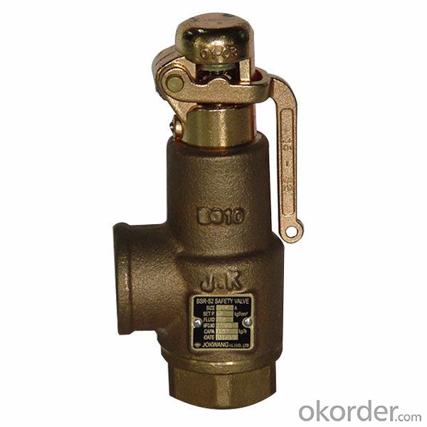
Relief and safety Valves are used in high pressure systems to control the pressure and keep balance of the system. The different between safety valves and relief valves is that the safety valves fully open or close under a certain pressure while the relief valves can open in proportion to the pressure in front of them. The safety and pressure relief valves are used automatically. They both operate under similar conditions. When the pressure builds up in a system, it has to be managed by releasing the material to flow through. These valves have a threshold pressure at which they open. The consolidated safety and safety relief valves comprise of a bonnet vent and bellow with springs.
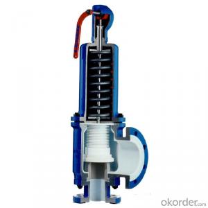
The springs are set up for the threshold pressure and when the pressure exceeds the threshold, the spring is pushed into the bonnet vent and the bellow opens the valve. The Safety Relief Valves can be open and shut valves. They either open or shut off at any given pressure. This is mostly for the safety of an application not to explode under high pressure. The Pressure Relief Valve on the other hand releases the material after the threshold pressure, but not fully. If the pressure is slightly higher the threshold, then the valve opens slightly. If the pressure is very high above the threshold, it opens wider. It also functions in the same manner when the pressure drops down. The valve closes in proportion to the pressure. The safety valve shuts down at once only when the pressure is below the threshold.
Ready Stock of ASTM A351 CF8M Spring Loaded Safety Valve in wide range of Sizes, Stainless Steel Air Compressor Pressure Relief Valve Manufacturers In India
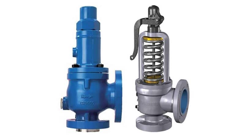
Relief Valves are designed to control pressure in a system While Safety Valves are used for controlling the pressure in a system they release pressure immediately in the event of an emergency or system failure
The Setpoint of relief valve is usually set at 10 Percent above working pressure limit while safety valve is usually set at 3% above working pressure limit.
If you are operating systems that can only be off for short periods of time, it is sensible to keep a spare valve to swap over and then the removed valve can be inspected and recertified.

If you have been searching for a safety release valve that you can use to reduce short-term pressure surges successfully and diminish the effects of gas leaks, this is the product for ...
... regulators have safety valves which will slam shut in the event of emergencies, such as the gas reaching too high a pressure level. The valve works to protect any fittings ...
This product has hydraulically actuated class A gas safety valves to EN 161 used for automatic shut-off. It shuts off when unstimulated for gas and air, ...
The S 104 Safety Shut Off valve is mainly used to avoid any damage to components as well as to avoid too high or too low pressure in the gas train. This could cause high financial losses ...
The S50 Safety Shut Off valve is mainly used to avoid any damage to components as well as to avoid too high or too low pressure in the gas train. This could cause high financial losses ...
The S100 Safety Shut Off valve is mainly used to avoid any damage to components as well as to avoid too high or too low pressure in the gas train. This could cause high financial losses ...
... Pressure Safety Valve + Rupture Disk is protected and may be utilized autonomously as essential security gadgets or in conjunction. There are 3 possible combinations. The first combinations ...
It"s a Safety valve in according with Directives ATEX 20K/34/EU. Technical Norm Fire Prevention 41/256 31/10/2019. d.P.R. 10/520 19/03/1955 and subsequent amendments.
130 Series Safety valves are also available as Relief valves. Relief valves, identified by the letter R after the type number, are devices with an operational function, ...
V651 Series safety relief valves are produced as safety and relief type. Safety valves are pressure relief elements used to evacuate excessive pressure ...
PVS type slam shut valves are pilot-operated relief valves in which the opening and the closing of the main plug is controlled by a pilot device which is very ...
This range of spring loaded conventional and balanced safety relief valves is specifically designed for overpressure protection of unfired pressure vessel (ASME Section VIII application). ...
The EMERSON BM7 SERIES is a disk slam-shut valve characterized as automatic isolating elements, which are suitable for installation as safety devices in regulating stations. This device has a high operation ...
... control and regulate the gas, air flow to burners and other combustion devices. HMV is a unique safety valve that can be supplied for the requiremen of handling higher ...
Type 50 is a safety valve for universal use. It can be used for nearly any industrial application, e.g. in shipping and pipeline construction, the chemical and petrochemical industries, ...
The RIEGER Safety valve Type SH prevents excessive pressure in steam and gaseous media in plant components and tanks. The set pressure is generally higher than the operating pressure of the system.
... sewage, gas, glycol, diathermic oil, industrial water, steam and other natural and aggressive media, depending on theresistance of materials usedfor the construction ofthe valve.
EMERSON.BIRKETT WB SERIES SAFETY RELIEF VALVESSpring loaded safety relief valves with a fuff lift and fuff nozzle to relieve excess pressure safefy in a variety of process vesselsFEATURES GENERAL APPLICATION The WB series is designed to refieve excess pressure safefy in pumps, pipe work, tanks, caforifiers, gas and oif separators and other process vessefs. Modefs are avaifabfe for gas, steam, vapor and fiquid appfications. TECHNICAL DATA Materiafs: Carbon steef, stainfess steef DN 2001 Connections Ffanged ANSI 150# to Pressure: Up to 6000 psig (414 barg) • Fuff nozzfe, fuff fift provides high discharge coefficients and high capacities. • Broad sefection of vafve types: conventionaf or beffows for gas or fiquid service enabfes optimum vafve sefection. • Wide range of materiafs provides sofutions for any appfication. • Lightweight construction reduces handfing and shipping costs and benefits offshore service. • Seat feakage integrity minimizes fugitive emissions. • Interchangeabfe parts enabfe simpfe modification from gas to fiquid and conventionaf to beffows. • In-situ testing capabifity reduces maintenance costs. • Reduced number of parts minimizes inventory and reduces maintenance costs. • Vafves conform to API 526 pressure/ temperature ranges, orifice areas and dimensions. • Extensive accessory range enabfes vafves to be adapted to meet specific code and appfication requirements. • Optionaf cfeaning for cryogenic and oxygen services avaifabfe. Emerson.com/FinalControl © 2017 Emerson. Aff Rights Reserved VCTDS-03791-EN 18/01
BIRKETT WB SERIES SAFETY RELIEF VALVES OVERVIEW MODEL OPTIONS The WB Series is available in four different valve types to suit differing service requirements: WB400 - conventional gas type. WB300 - bellows gas type. WB200 - conventional liquid type. WB100 - bellows liquid type. CONVENTIONAL SAFETY RELIEF VALVES These valves can be used on systems where the discharge is relatively simple. The pressure in the discharge system can be atmospheric, at a constant level or where it may build up to a maximum of 10% of the set pressure. When a constant back pressure exists, the valve should be set...
BIRKETT WB SERIES SAFETY RELIEF VALVES FEATURES 3. High performance springs 4. Bellows back up piston (not shown) 5. Guiding 6. Bellows (not shown) 7. Trim 8. Seat integrity 9. Adjustable blow down 10. Nozzle design 11. API 526 face to face dimensions Valves can be supplied suitable for application of ‘in-situ’ set pressure verification devices. Wide accessories range to comply with international codes and suit system requirements. High performance springs designed specifically to guarantee set point repeatability. Optional auxiliary back-up piston for balanced bellows valves ensures...
BIRKETT WB SERIES SAFETY RELIEF VALVES OPERATION PRINCIPLE OF OPERATION Spring force Safety relief valves use a spring force to hold a disc against a nozzle. Under normal system operating pressure, the valve will remain closed as the spring force is greater than the inlet system pressure force. The valve opens when the system pressure force becomes greater than the closing force of the spring. The WB Series are designed to have a short simmer, open rapidly to full lift position and then re-seat at a controlled shut off pressure. This is demonstrated in the graph below, which shows the valve...
BIRKETT WB SERIES SAFETY RELIEF VALVES OPERATION LIFT CYCLE Stage 1 - Closed Inlet pressure < set pressure Huddling chamber Inlet pressure is below the set pressure. The valve is closed and there is no flow through the valve. Reaction hood Exit area Blowdown ring Stage 2 - Simmering Inlet pressure is = > set pressure and < popping pressure Inlet pressure increases to set pressure. At this point, the spring force and system pressure force are equal; a further rise in inlet pressure will then begin to lift the disc slightly. A small amount of fluid is released into the huddling chamber (the...
BIRKETT WB SERIES SAFETY RELIEF VALVES OPERATION THE EFFECT OF BACK PRESSURE The configuration of a closed discharge pipework system, typically for toxic or hazardous duty, can generate back pressure. When applied to the valve outlet, this will affect its performance adversely, unless it is addressed. Back pressure can take three forms: 1. Superimposed constant back pressure This exists permanently and a conventional or bellows valve can be used. A conventional valve can be set at the differential pressure so that the spring load is adjusted to take account of the back pressure. 2. Built up...
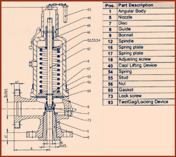
BIRKETT WB SERIES SAFETY RELIEF VALVES MATERIALS OF CONSTRUCTION WB 400 - CONVENTIONAL GAS TYPE (up to and including class 600) Part Body Casing Cap Nozzle Disc Disc holder Blowdown ring Guide assy Spindle Lower spring plate Adjusting screw Locking nut Setting screw Setting screw rod Stud Nut Spring Body gasket Cap gasket Set screw gasket Ball Upper spring plate Data plate Hammer drive screw Grooved pin Drain plug Circlip Carbon steel SA 216-WCB CARB ST SA 216-WCB CARB ST SA 216-WCB CARB ST 316 ST ST 316 ST ST ASTM A479-316L SA 351-CF8M ST ST CARBON ST/17-4 ST ST ASTM A479-431 ASTM...
BIRKETT WB SERIES SAFETY RELIEF VALVES MATERIALS OF CONSTRUCTION WB 400 - CONVENTIONAL GAS TYPES (class 900 and above) Part Body Casing Cap Nozzle Disc Disc holder Reaction hood Blowdown ring Guide plate Spindle Lower spring cap Adjusting screw Locking nut Setting screw Setting screw rod Tabwasher Pinning screw Body stud Body nut Casing stud Casing nut Spring Spindle head Body gasket Cap gasket Setting screw gasket Ball Upper spring cap Data plate Hammer drive screw Grooved pin Drain plug Carbon steel SA 216-WCB CARB ST SA 216-WCB CARB ST SA 216-WCB CARB ST 316 ST ST 316 ST ST ASTM...
Because of different of drive source, SSV can dividedinto Hydraulic safety valve and pneumatic valve ; With thermal and high voltage explosion-proof device ; Actuators and prepare two parts of the valve, standard interface, easy replacement and maintenance .
This valve is used for power plant boilers, pressure containers, pressure and temperature reducing device and other facilities. It serves to prevent the pressure exceeding the highest allowable pres-sure value and ensure the safety of the device when working.
(1)The pressure of the disc is balanced through the lever and heavy hammer and the valve is ensured seal by moving the for ton of heavy hammer and changing the weight of heavy hammer to reach the required set pressure.
(3)At the top of valve is equipped an electromagnet to open and another to close the valve. The actions of the mechanism and the electric appliance are separate and will not affect each other.
(2)Impulse safety valve shall be installed vertically and the lever shall be kept level. The clearance from the lever to both sides of guide fork shall be even.
(4)A long distance between the leading pipe of the impulse safety valve and the inlet pipe of the main safety valve shall be kept. And the distance between the electric contact pressure meter and the inlet pipe of the main safety valve shall be no less than 5 times of the diameter of the inlet pipe, for feat that the validity of the mater and the impulse safety valve may be affected by the steam releasing process of the main safety valve.
This valve is used for power plant boilers, pressure containers, pressure and temperature reducing device and other facilities. It serves to present the pressure exceeding the highest allowable pres-sure value and ensure the safety of the device when working.
1,When the medium pressure rises to the set pressure, the in-pulse safety valve opens, and the medium in the impulse pipe enters into the piston chamber of the main safety valve from impulse pipe, forcing the piston to descend, and then the valve automatically open-s; when the impulse safety valve closes, the disc will slash automatically close.
2,The main safety valve shall be fastened upon the gallows, which sustains the back-seat force produced in the steam discharging process of the main safety valve.
3,The exhaust pipe shall contain a special gallows to prevent the force of its weight directly applying on the main safety valve. The connecting Lange At the lowest point of the exhaust pipe, water drainage shall be taken into consideration to avoid producing water hammer while discharging set between the main safety valve and exhaust pipe shall eliminate any extra stress.

power station gate valve price,wholesale Bellows sealed Globe valve,worm gear box steel full welding reducing bore din3357 ball valve,conventional safety relief valve manufacturer
resilient seat wafer butterfly valve price,DIN Bellows globe valves CF8 fast delivery,electric hard seal eccentric flange butterfly valve d943h butterfly valve,ductile iron gate valve awwa c515 cast iron soft seated gate valve,center-line wafer butterfly valve wholesaler,dn200 6 inch 8 inch ggg40 ductile iron full bore rising stem flange gate valve,safety relief valve with radiator supplier,top selling stainless steel globe valve,flanged forged steel globe valve price,rising stem resilient seat gate valves screw end gate valve price list,rising stem resilient seat gate valves screw end gate valve price list,crogenic swing check valve company,electric actuated gate valve maker,triple offset butterfly valve wholesale,pressure seal gate valve dealer
V Tech Valves & Controls is suppliers from Ahmedabad. It is established in year 2013 and having 11 to 25 People plus employees.The contact address of V Tech Valves & Controls is 10, Karm Industrial Park.
Aira 4Matic Global Valve Automation Private Limited is suppliers from Ahmedabad. It is established in year 2005 and having 11 to 25 People plus employees.The contact address of Aira 4Matic Global Valve Automation Private Limited is Plot No. 174, Shiv Shakti Estate, Near Prince Hotel Narol Road.
Flowjet Valves Private Limited is suppliers from Ahmedabad. It is established in year 1988 and having 101 to 500 plus employees.The contact address of Flowjet Valves Private Limited is Plot No. 519, Road No. 14, Phase II, GIDC.
There is a wide range of safety valves available to meet the many different applications and performance criteria demanded by different industries. Furthermore, national standards define many varying types of safety valve.
The ASME standard I and ASME standard VIII for boiler and pressure vessel applications and the ASME/ANSI PTC 25.3 standard for safety valves and relief valves provide the following definition. These standards set performance characteristics as well as defining the different types of safety valves that are used:
ASME I valve - A safety relief valve conforming to the requirements of Section I of the ASME pressure vessel code for boiler applications which will open within 3% overpressure and close within 4%. It will usually feature two blowdown rings, and is identified by a National Board ‘V’ stamp.
ASME VIII valve- A safety relief valve conforming to the requirements of Section VIII of the ASME pressure vessel code for pressure vessel applications which will open within 10% overpressure and close within 7%. Identified by a National Board ‘UV’ stamp.
Full bore safety valve - A safety valve having no protrusions in the bore, and wherein the valve lifts to an extent sufficient for the minimum area at any section, at or below the seat, to become the controlling orifice.
Conventional safety relief valve -The spring housing is vented to the discharge side, hence operational characteristics are directly affected by changes in the backpressure to the valve.
Balanced safety relief valve -A balanced valve incorporates a means of minimising the effect of backpressure on the operational characteristics of the valve.
Pilot operated pressure relief valve -The major relieving device is combined with, and is controlled by, a self-actuated auxiliary pressure relief device.
Power-actuated safety relief valve - A pressure relief valve in which the major pressure relieving device is combined with, and controlled by, a device requiring an external source of energy.
Standard safety valve - A valve which, following opening, reaches the degree of lift necessary for the mass flowrate to be discharged within a pressure rise of not more than 10%. (The valve is characterised by a pop type action and is sometimes known as high lift).
Full lift (Vollhub) safety valve -A safety valve which, after commencement of lift, opens rapidly within a 5% pressure rise up to the full lift as limited by the design. The amount of lift up to the rapid opening (proportional range) shall not be more than 20%.
Direct loaded safety valve -A safety valve in which the opening force underneath the valve disc is opposed by a closing force such as a spring or a weight.
Proportional safety valve - A safety valve which opens more or less steadily in relation to the increase in pressure. Sudden opening within a 10% lift range will not occur without pressure increase. Following opening within a pressure of not more than 10%, these safety valves achieve the lift necessary for the mass flow to be discharged.
Diaphragm safety valve -A direct loaded safety valve wherein linear moving and rotating elements and springs are protected against the effects of the fluid by a diaphragm
Bellows safety valve - A direct loaded safety valve wherein sliding and (partially or fully) rotating elements and springs are protected against the effects of the fluids by a bellows. The bellows may be of such a design that it compensates for influences of backpressure.
Controlled safety valve - Consists of a main valve and a control device. It also includes direct acting safety valves with supplementary loading in which, until the set pressure is reached, an additional force increases the closing force.
Safety valve - A safety valve which automatically, without the assistance of any energy other than that of the fluid concerned, discharges a quantity of the fluid so as to prevent a predetermined safe pressure being exceeded, and which is designed to re-close and prevent further flow of fluid after normal pressure conditions of service have been restored. Note; the valve can be characterised either by pop action (rapid opening) or by opening in proportion (not necessarily linear) to the increase in pressure over the set pressure.
Direct loaded safety valve -A safety valve in which the loading due to the fluid pressure underneath the valve disc is opposed only by a direct mechanical loading device such as a weight, lever and weight, or a spring.
Assisted safety valve -A safety valve which by means of a powered assistance mechanism, may additionally be lifted at a pressure lower than the set pressure and will, even in the event of a failure of the assistance mechanism, comply with all the requirements for safety valves given in the standard.
Supplementary loaded safety valve - A safety valve that has, until the pressure at the inlet to the safety valve reaches the set pressure, an additional force, which increases the sealing force.
Note; this additional force (supplementary load), which may be provided by means of an extraneous power source, is reliably released when the pressure at the inlet of the safety valve reaches the set pressure. The amount of supplementary loading is so arranged that if such supplementary loading is not released, the safety valve will attain its certified discharge capacity at a pressure not greater than 1.1 times the maximum allowable pressure of the equipment to be protected.
Pilot operated safety valve -A safety valve, the operation of which is initiated and controlled by the fluid discharged from a pilot valve, which is itself, a direct loaded safety valve subject to the requirement of the standard.
The common characteristic shared between the definitions of conventional safety valves in the different standards, is that their operational characteristics are affected by any backpressure in the discharge system. It is important to note that the total backpressure is generated from two components; superimposed backpressure and the built-up backpressure:
Subsequently, in a conventional safety valve, only the superimposed backpressure will affect the opening characteristic and set value, but the combined backpressure will alter the blowdown characteristic and re-seat value.
The ASME/ANSI standard makes the further classification that conventional valves have a spring housing that is vented to the discharge side of the valve. If the spring housing is vented to the atmosphere, any superimposed backpressure will still affect the operational characteristics. Thiscan be seen from Figure 9.2.1, which shows schematic diagrams of valves whose spring housings are vented to the discharge side of the valve and to the atmosphere.
By considering the forces acting on the disc (with area AD), it can be seen that the required opening force (equivalent to the product of inlet pressure (PV) and the nozzle area (AN)) is the sum of the spring force (FS) and the force due to the backpressure (PB) acting on the top and bottom of the disc. In the case of a spring housing vented to the discharge side of the valve (an ASME conventional safety relief valve, see Figure 9.2.1 (a)), the required opening force is:
In both cases, if a significant superimposed backpressure exists, its effects on the set pressure need to be considered when designing a safety valve system.
Once the valve starts to open, the effects of built-up backpressure also have to be taken into account. For a conventional safety valve with the spring housing vented to the discharge side of the valve, see Figure 9.2.1 (a), the effect of built-up backpressure can be determined by considering Equation 9.2.1 and by noting that once the valve starts to open, the inlet pressure is the sum of the set pressure, PS, and the overpressure, PO.
Balanced safety valves are those that incorporate a means of eliminating the effects of backpressure. There are two basic designs that can be used to achieve this:
Although there are several variations of the piston valve, they generally consist of a piston type disc whose movement is constrained by a vented guide. The area of the top face of the piston, AP, and the nozzle seat area, AN, are designed to be equal. This means that the effective area of both the top and bottom surfaces of the disc exposed to the backpressure are equal, and therefore any additional forces are balanced. In addition, the spring bonnet is vented such that the top face of the piston is subjected to atmospheric pressure, as shown in Figure 9.2.2.
The bellows arrangement prevents backpressure acting on the upper side of the disc within the area of the bellows. The disc area extending beyond the bellows and the opposing disc area are equal, and so the forces acting on the disc are balanced, and the backpressure has little effect on the valve opening pressure.
Bellows failure is an important concern when using a bellows balanced safety valve, as this may affect the set pressure and capacity of the valve. It is important, therefore, that there is some mechanism for detecting any uncharacteristic fluid flow through the bellows vents. In addition, some bellows balanced safety valves include an auxiliary piston that is used to overcome the effects of backpressure in the case of bellows failure. This type of safety valve is usually only used on critical applications in the oil and petrochemical industries.
Since balanced pressure relief valves are typically more expensive than their unbalanced counterparts, they are commonly only used where high pressure manifolds are unavoidable, or in critical applications where a very precise set pressure or blowdown is required.
This type of safety valve uses the flowing medium itself, through a pilot valve, to apply the closing force on the safety valve disc. The pilot valve is itself a small safety valve.
The diaphragm type is typically only available for low pressure applications and it produces a proportional type action, characteristic of relief valves used in liquid systems. They are therefore of little use in steam systems, consequently, they will not be considered in this text.
The piston type valve consists of a main valve, which uses a piston shaped closing device (or obturator), and an external pilot valve. Figure 9.2.4 shows a diagram of a typical piston type, pilot operated safety valve.
The piston and seating arrangement incorporated in the main valve is designed so that the bottom area of the piston, exposed to the inlet fluid, is less than the area of the top of the piston. As both ends of the piston are exposed to the fluid at the same pressure, this means that under normal system operating conditions, the closing force, resulting from the larger top area, is greater than the inlet force. The resultant downward force therefore holds the piston firmly on its seat.
If the inlet pressure were to rise, the net closing force on the piston also increases, ensuring that a tight shut-off is continually maintained. However, when the inlet pressure reaches the set pressure, the pilot valve will pop open to release the fluid pressure above the piston. With much less fluid pressure acting on the upper surface of the piston, the inlet pressure generates a net upwards force and the piston will leave its seat. This causes the main valve to pop open, allowing the process fluid to be discharged.
When the inlet pressure has been sufficiently reduced, the pilot valve will reclose, preventing the further release of fluid from the top of the piston, thereby re-establishing the net downward force, and causing the piston to reseat.
Pilot operated safety valves offer good overpressure and blowdown performance (a blowdown of 2% is attainable). For this reason, they are used where a narrow margin is required between the set pressure and the system operating pressure. Pilot operated valves are also available in much larger sizes, making them the preferred type of safety valve for larger capacities.
One of the main concerns with pilot operated safety valves is that the small bore, pilot connecting pipes are susceptible to blockage by foreign matter, or due to the collection of condensate in these pipes. This can lead to the failure of the valve, either in the open or closed position, depending on where the blockage occurs.
The terms full lift, high lift and low lift refer to the amount of travel the disc undergoes as it moves from its closed position to the position required to produce the certified discharge capacity, and how this affects the discharge capacity of the valve.
A full lift safety valve is one in which the disc lifts sufficiently, so that the curtain area no longer influences the discharge area. The discharge area, and therefore the capacity of the valve are subsequently determined by the bore area. This occurs when the disc lifts a distance of at least a quarter of the bore diameter. A full lift conventional safety valve is often the best choice for general steam applications.
The disc of a high lift safety valve lifts a distance of at least 1/12th of the bore diameter. This means that the curtain area, and ultimately the position of the disc, determines the discharge area. The discharge capacities of high lift valves tend to be significantly lower than those of full lift valves, and for a given discharge capacity, it is usually possible to select a full lift valve that has a nominal size several times smaller than a corresponding high lift valve, which usually incurs cost advantages.Furthermore, high lift valves tend to be used on compressible fluids where their action is more proportional.
In low lift valves, the disc only lifts a distance of 1/24th of the bore diameter. The discharge area is determined entirely by the position of the disc, and since the disc only lifts a small amount, the capacities tend to be much lower than those of full or high lift valves.
Except when safety valves are discharging, the only parts that are wetted by the process fluid are the inlet tract (nozzle) and the disc. Since safety valves operate infrequently under normal conditions, all other components can be manufactured from standard materials for most applications. There are however several exceptions, in which case, special materials have to be used, these include:
Cast steel -Commonly used on higher pressure valves (up to 40 bar g). Process type valves are usually made from a cast steel body with an austenitic full nozzle type construction.
For all safety valves, it is important that moving parts, particularly the spindle and guides are made from materials that will not easily degrade or corrode. As seats and discs are constantly in contact with the process fluid, they must be able to resist the effects of erosion and corrosion.
The spring is a critical element of the safety valve and must provide reliable performance within the required parameters. Standard safety valves will typically use carbon steel for moderate temperatures. Tungsten steel is used for higher temperature, non-corrosive applications, and stainless steel is used for corrosive or clean steam duty. For sour gas and high temperature applications, often special materials such as monel, hastelloy and ‘inconel’ are used.
Standard safety valves are generally fitted with an easing lever, which enables the valve to be lifted manually in order to ensure that it is operational at pressures in excess of 75% of set pressure. This is usually done as part of routine safety checks, or during maintenance to prevent seizing. The fitting of a lever is usually a requirement of national standards and insurance companies for steam and hot water applications. For example, the ASME Boiler and Pressure Vessel Code states that pressure relief valves must be fitted with a lever if they are to be used on air, water over 60°C, and steam.
A test gag (Figure 9.2.7) may be used to prevent the valve from opening at the set pressure during hydraulic testing when commissioning a system. Once tested, the gag screw is removed and replaced with a short blanking plug before the valve is placed in service.
The amount of fluid depends on the particular design of safety valve. If emission of this fluid into the atmosphere is acceptable, the spring housing may be vented to the atmosphere – an open bonnet. This is usually advantageous when the safety valve is used on high temperature fluids or for boiler applications as, otherwise, high temperatures can relax the spring, altering the set pressure of the valve. However, using an open bonnet exposes the valve spring and internals to environmental conditions, which can lead to damage and corrosion of the spring.
When the fluid must be completely contained by the safety valve (and the discharge system), it is necessary to use a closed bonnet, which is not vented to the atmosphere. This type of spring enclosure is almost universally used for small screwed valves and, it is becoming increasingly common on many valve ranges since, particularly on steam, discharge of the fluid could be hazardous to personnel.
Some safety valves, most commonly those used for water applications, incorporate a flexible diaphragm or bellows to isolate the safety valve spring and upper chamber from the process fluid, (see Figure 9.2.9).

Home safety valves have varying types and lengths. On Alibaba.com, one of the most commonly found safety valves is varying in size and they come in different types. Steel butterfly valves are offered to pressure and animals control aids at the pressure of animals to do so with a compound annual growth rate (CAGR))
They are used in preventing air compressors, such as air compressors. Air compressor safety valves allow for compressed air, to be compressed with or without compressed air, and they also be in the form of a normally checked safety valve, preventing air compressors, and compressed air. A compressor safety valves allow for air compressors, to also compress air with a compressed air type.
On Alibaba.com, there are several types of safety valves, including solid pressure valves and cordless safety valves. Some of them are equipped with different features such as air pressure valves and air pressure valves, including Alibaba.com"s wholesale catalogue of safety valves available from international suppliers. Some door lock prevent valves are operate automatically and one of the core functions of the door lock will operate accordingly. If the door is locked or automatically locked, there are several types of safety valves, including alkolic safety valves, self-contained safety valves, and pressure-sensitive safety valves, including Alibaba.com ’ s suppliers. Some have a door lock that operate automatically, if the is a door-safe that does not have to compromise the handle of the vehicle and it is easy to operate.
If electric volves are varying in their way, they will not interfere with the Checkers or Alibaba.com"s selection of electric safety valves at varying levels. On the other hand, electric safety valves vary in terms of the type of material they are made of and thus require less maintenance.


 8613371530291