
conventional safety valve quotation

Q4. How to proceed an order for valve?A: Firstly let us know your requirements or application. Secondly We quote according to your requirements or our suggestions.
Conventional Safety Relief Valves are those which work on simple working principle of force balance. The operation of a conventional spring-loaded PSV/SRV is based on a force balance principle. Under normal operating conditions, until the pressure at the inlet is below the set pressure or opening pressure, the disc is seated on the nozzle preventing flow through the nozzle.
Relief and safety Valves are used in high pressure systems to control the pressure and keep balance of the system. The different between safety valves and relief valves is that the safety valves fully open or close under a certain pressure while the relief valves can open in proportion to the pressure in front of them. The safety and pressure relief valves are used automatically. They both operate under similar conditions. When the pressure builds up in a system, it has to be managed by releasing the material to flow through. These valves have a threshold pressure at which they open. The consolidated safety and safety relief valves comprise of a bonnet vent and bellow with springs.
The springs are set up for the threshold pressure and when the pressure exceeds the threshold, the spring is pushed into the bonnet vent and the bellow opens the valve. The Safety Relief Valves can be open and shut valves. They either open or shut off at any given pressure. This is mostly for the safety of an application not to explode under high pressure. The Pressure Relief Valve on the other hand releases the material after the threshold pressure, but not fully. If the pressure is slightly higher the threshold, then the valve opens slightly. If the pressure is very high above the threshold, it opens wider. It also functions in the same manner when the pressure drops down. The valve closes in proportion to the pressure. The safety valve shuts down at once only when the pressure is below the threshold.
Ready Stock of ASTM A351 CF8M Spring Loaded Safety Valve in wide range of Sizes, Stainless Steel Air Compressor Pressure Relief Valve Manufacturers In India
Relief Valves are designed to control pressure in a system While Safety Valves are used for controlling the pressure in a system they release pressure immediately in the event of an emergency or system failure
The Setpoint of relief valve is usually set at 10 Percent above working pressure limit while safety valve is usually set at 3% above working pressure limit.
If you are operating systems that can only be off for short periods of time, it is sensible to keep a spare valve to swap over and then the removed valve can be inspected and recertified.

Because of different of drive source, SSV can dividedinto Hydraulic safety valve and pneumatic valve ; With thermal and high voltage explosion-proof device ; Actuators and prepare two parts of the valve, standard interface, easy replacement and maintenance .
This valve is used for power plant boilers, pressure containers, pressure and temperature reducing device and other facilities. It serves to prevent the pressure exceeding the highest allowable pres-sure value and ensure the safety of the device when working.
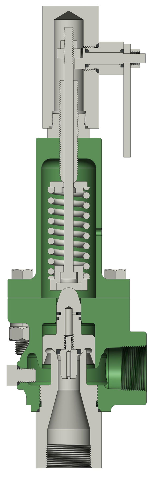
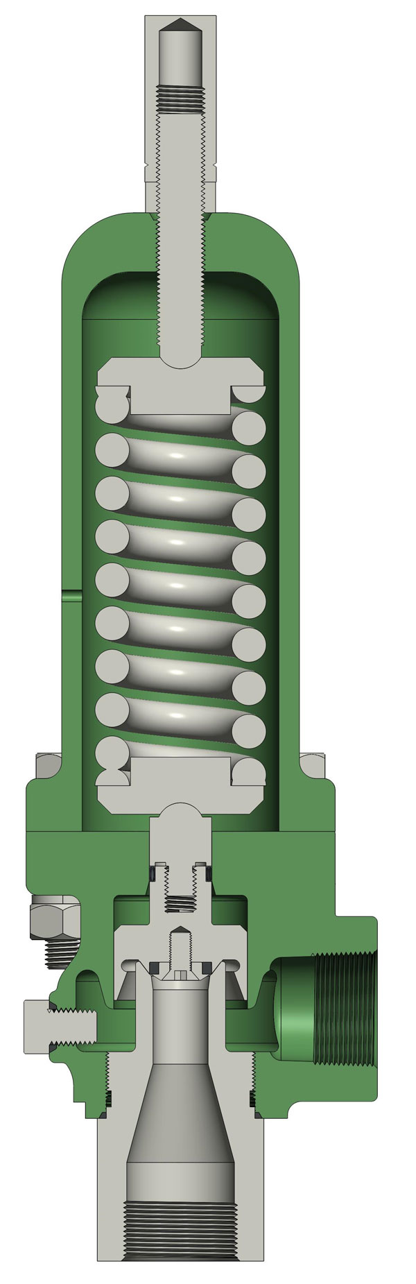
(1)The pressure of the disc is balanced through the lever and heavy hammer and the valve is ensured seal by moving the for ton of heavy hammer and changing the weight of heavy hammer to reach the required set pressure.
(3)At the top of valve is equipped an electromagnet to open and another to close the valve. The actions of the mechanism and the electric appliance are separate and will not affect each other.
(2)Impulse safety valve shall be installed vertically and the lever shall be kept level. The clearance from the lever to both sides of guide fork shall be even.
(4)A long distance between the leading pipe of the impulse safety valve and the inlet pipe of the main safety valve shall be kept. And the distance between the electric contact pressure meter and the inlet pipe of the main safety valve shall be no less than 5 times of the diameter of the inlet pipe, for feat that the validity of the mater and the impulse safety valve may be affected by the steam releasing process of the main safety valve.
This valve is used for power plant boilers, pressure containers, pressure and temperature reducing device and other facilities. It serves to present the pressure exceeding the highest allowable pres-sure value and ensure the safety of the device when working.
1,When the medium pressure rises to the set pressure, the in-pulse safety valve opens, and the medium in the impulse pipe enters into the piston chamber of the main safety valve from impulse pipe, forcing the piston to descend, and then the valve automatically open-s; when the impulse safety valve closes, the disc will slash automatically close.
2,The main safety valve shall be fastened upon the gallows, which sustains the back-seat force produced in the steam discharging process of the main safety valve.
3,The exhaust pipe shall contain a special gallows to prevent the force of its weight directly applying on the main safety valve. The connecting Lange At the lowest point of the exhaust pipe, water drainage shall be taken into consideration to avoid producing water hammer while discharging set between the main safety valve and exhaust pipe shall eliminate any extra stress.
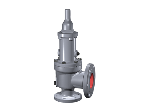
The safety valves / pressure relief valves provided by Weldon mainly include spring-loaded safety valve, pilot-operated safety valve, bellow balanced safety valve and changeover valve (switch device). The calculation sheet could be provided for all projetc and all the safety valves are designed and manufactured according to API 2000, API PR520 and API 526.
Safety valve is the safe guard in the pressure vessels such as chemical plants, eletcric power boilers and gas storage tanks, acting as a protetcion equipment from exploding or damaging. The safety relief valve is opened automatically to relief when the system pressure exceeds the set pressure, and resumes closed when the system pressure bellow the set pressure.
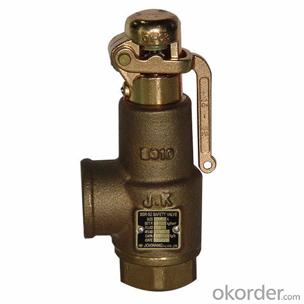
The Spring-loaded safety valves is the most conventional safety valve, the spring load is preset to equal the force the inlet fluid exerts on the closed disk when the system pressure is at the set pressure of the valve. As the pressure exceeds a set value, the spring opens releasing the disc and the fluid flowing through the valve.
The Pilot-operated safety valves are composed of a "pilot valve" and a "main valve", differently from spring-loaded safety valves, the pressure is monitored and adjusted by the pilot valve, not the main valve. Pilot-operated safety valves are widely used for large size valve and high-pressure applications, which need lager torque and high reliability.
Bellow balanced safety valves are designed to reduce the effetc of back pressure accumulation, the "Bellows" located between the bonnet and the valve body, where maintained free from the effetc of back pressure, the opposing pressure on the inlet fluid is only generated by the spring without contribution from any sort of backpressure. The space enclosed by bellows is freely vented to air, the back pressure is expetced to be 10 - 50% of the set pressure. The Bellows can also protetc the spring and other trim components from corrosive media.
Breather Valves, also named Pressure/Vacuum Relief Valves, available with flanged outlets or vented to atmosphere, are special types of Relief Valves which are specifically designed for tank protetcion. Breather Valves are usually installed in the in-and out breathing lines of tanks, vessels and process equipment to prevent the of excessive pressure or vacuum which can unbalance the system or damage the storage vessels.
Changeover valves, also called Switch valves, are designed to connetc two safety valves to a single pressurized system, acting as the three ways devices for flow seletcion in a pipeline.
Through these Changeover valves, one of the two safety valves is in operation and ensures the protetcion of the system, the other safety valve is in "stand by" ready to come into operation if the first one must be changed or removed to maintenance. Changeover valves are often required for the continuous production.

Farris Relief Valves, Series 3800, 2600 and 2700 Farris Relief Valves are ASME NB Certified for air, steam and water. These valve models are European CE Approved. They come in sizes 1 X 2-12 X 16. Series 3800 Farris Relief Valves actual orifice areas range from 0.15-109 square inches and can handle pressures from 20-6170 psig and handle -450° F-500° F. We also offer Farris valve parts, Worcester valve parts, and Worcester positioners. Contact us to find out more about our Farris and Worcester brands. You can also browse our catalog.
The optional balanced bellows design isolates working parts and top-works from corrosion, and nullifies the effects of back pressure on valve performance. The "D" to "T" orifices of the Series 2600 Farris Relief Valves meet API Standard 526 covering orifice areas and center-to-face dimensions. Optional Farris Safety Valves construction materials include 316 stainless steel, Monel®, and Hastelloy® C. The Farris Safety Valves are available with Farris Valve Parts in compliance with NACE standards.

SAFECON - Series SC- 5000 SAFETY / PRESSURE RELIEF VALVES are designed and manufactured in compliance with API 520 / ASME Section Vlll Division l for High performance application for use on vapor, gas and liquid for over pressure protection. This Conventional safety / pressure relief valves are versatile, safe & interchangeable.
A safety valve is a valve that acts as a fail-safe. An example of safety valve is a pressure relief valve (PRV), which automatically releases a substance from a boiler, pressure vessel, or other system, when the pressure or temperature exceeds preset limits. Pilot-operated relief valves are a specialized type of pressure safety valve. A leak tight, lower cost, single emergency use option would be a rupture disk.
Safety valves were first developed for use on steam boilers during the Industrial Revolution. Early boilers operating without them were prone to explosion unless carefully operated.
Vacuum safety valves (or combined pressure/vacuum safety valves) are used to prevent a tank from collapsing while it is being emptied, or when cold rinse water is used after hot CIP (clean-in-place) or SIP (sterilization-in-place) procedures. When sizing a vacuum safety valve, the calculation method is not defined in any norm, particularly in the hot CIP / cold water scenario, but some manufacturers
The earliest and simplest safety valve was used on a 1679 steam digester and utilized a weight to retain the steam pressure (this design is still commonly used on pressure cookers); however, these were easily tampered with or accidentally released. On the Stockton and Darlington Railway, the safety valve tended to go off when the engine hit a bump in the track. A valve less sensitive to sudden accelerations used a spring to contain the steam pressure, but these (based on a Salter spring balance) could still be screwed down to increase the pressure beyond design limits. This dangerous practice was sometimes used to marginally increase the performance of a steam engine. In 1856, John Ramsbottom invented a tamper-proof spring safety valve that became universal on railways. The Ramsbottom valve consisted of two plug-type valves connected to each other by a spring-laden pivoting arm, with one valve element on either side of the pivot. Any adjustment made to one of valves in an attempt to increase its operating pressure would cause the other valve to be lifted off its seat, regardless of how the adjustment was attempted. The pivot point on the arm was not symmetrically between the valves, so any tightening of the spring would cause one of the valves to lift. Only by removing and disassembling the entire valve assembly could its operating pressure be adjusted, making impromptu "tying down" of the valve by locomotive crews in search of more power impossible. The pivoting arm was commonly extended into a handle shape and fed back into the locomotive cab, allowing crews to "rock" both valves off their seats to confirm they were set and operating correctly.
Safety valves also evolved to protect equipment such as pressure vessels (fired or not) and heat exchangers. The term safety valve should be limited to compressible fluid applications (gas, vapour, or steam).
For liquid-packed vessels, thermal relief valves are generally characterized by the relatively small size of the valve necessary to provide protection from excess pressure caused by thermal expansion. In this case a small valve is adequate because most liquids are nearly incompressible, and so a relatively small amount of fluid discharged through the relief valve will produce a substantial reduction in pressure.
Flow protection is characterized by safety valves that are considerably larger than those mounted for thermal protection. They are generally sized for use in situations where significant quantities of gas or high volumes of liquid must be quickly discharged in order to protect the integrity of the vessel or pipeline. This protection can alternatively be achieved by installing a high integrity pressure protection system (HIPPS).
In the petroleum refining, petrochemical, chemical manufacturing, natural gas processing, power generation, food, drinks, cosmetics and pharmaceuticals industries, the term safety valve is associated with the terms pressure relief valve (PRV), pressure safety valve (PSV) and relief valve.
The generic term is Pressure relief valve (PRV) or pressure safety valve (PSV). PRVs and PSVs are not the same thing, despite what many people think; the difference is that PSVs have a manual lever to open the valve in case of emergency.
Relief valve (RV): an automatic system that is actuated by the static pressure in a liquid-filled vessel. It specifically opens proportionally with increasing pressure
Pilot-operated safety relief valve (POSRV): an automatic system that relieves on remote command from a pilot, to which the static pressure (from equipment to protect) is connected
Low pressure safety valve (LPSV): an automatic system that relieves static pressure on a gas. Used when the difference between the vessel pressure and the ambient atmospheric pressure is small.
Vacuum pressure safety valve (VPSV): an automatic system that relieves static pressure on a gas. Used when the pressure difference between the vessel pressure and the ambient pressure is small, negative and near to atmospheric pressure.
Low and vacuum pressure safety valve (LVPSV): an automatic system that relieves static pressure on a gas. Used when the pressure difference is small, negative or positive and near to atmospheric pressure.
In most countries, industries are legally required to protect pressure vessels and other equipment by using relief valves. Also, in most countries, equipment design codes such as those provided by the ASME, API and other organizations like ISO (ISO 4126) must be complied with. These codes include design standards for relief valves and schedules for periodic inspection and testing after valves have been removed by the company engineer.
Today, the food, drinks, cosmetics, pharmaceuticals and fine chemicals industries call for hygienic safety valves, fully drainable and Cleanable-In-Place. Most are made of stainless steel; the hygienic norms are mainly 3A in the USA and EHEDG in Europe.
The first safety valve was invented by Denis Papin for his steam digester, an early pressure cooker rather than an engine.steelyard" lever a smaller weight was required, also the pressure could easily be regulated by sliding the same weight back and forth along the lever arm. Papin retained the same design for his 1707 steam pump.Greenwich in 1803, one of Trevithick"s high-pressure stationary engines exploded when the boy trained to operate the engine left it to catch eels in the river, without first releasing the safety valve from its working load.
Although the lever safety valve was convenient, it was too sensitive to the motion of a steam locomotive. Early steam locomotives therefore used a simpler arrangement of weights stacked directly upon the valve. This required a smaller valve area, so as to keep the weight manageable, which sometimes proved inadequate to vent the pressure of an unattended boiler, leading to explosions. An even greater hazard was the ease with which such a valve could be tied down, so as to increase the pressure and thus power of the engine, at further risk of explosion.
Although deadweight safety valves had a short lifetime on steam locomotives, they remained in use on stationary boilers for as long as steam power remained.
Weighted valves were sensitive to bouncing from the rough riding of early locomotives. One solution was to use a lightweight spring rather than a weight. This was the invention of Timothy Hackworth on his leaf springs.
These direct-acting spring valves could be adjusted by tightening the nuts retaining the spring. To avoid tampering, they were often shrouded in tall brass casings which also vented the steam away from the locomotive crew.
The Salter coil spring spring balance for weighing, was first made in Britain by around 1770.spring steels to make a powerful but compact spring in one piece. Once again by using the lever mechanism, such a spring balance could be applied to the considerable force of a boiler safety valve.
The spring balance valve also acted as a pressure gauge. This was useful as previous pressure gauges were unwieldy mercury manometers and the Bourdon gauge had yet to be invented.
Paired valves were often adjusted to slightly different pressures too, a small valve as a control measure and the lockable valve made larger and permanently set to a higher pressure, as a safeguard.Sinclair for the Eastern Counties Railway in 1859, had the valve spring with pressure scale behind the dome, facing the cab, and the locked valve ahead of the dome, out of reach of interference.
In 1855, John Ramsbottom, later locomotive superintendent of the LNWR, described a new form of safety valve intended to improve reliability and especially to be tamper-resistant. A pair of plug valves were used, held down by a common spring-loaded lever between them with a single central spring. This lever was characteristically extended rearwards, often reaching into the cab on early locomotives. Rather than discouraging the use of the spring lever by the fireman, Ramsbottom"s valve encouraged this. Rocking the lever freed up the valves alternately and checked that neither was sticking in its seat.
A drawback to the Ramsbottom type was its complexity. Poor maintenance or mis-assembly of the linkage between the spring and the valves could lead to a valve that no longer opened correctly under pressure. The valves could be held against their seats and fail to open or, even worse, to allow the valve to open but insufficiently to vent steam at an adequate rate and so not being an obvious and noticeable fault.Rhymney Railway, even though the boiler was almost new, at only eight months old.
Naylor valves were introduced around 1866. A bellcrank arrangement reduced the strain (percentage extension) of the spring, thus maintaining a more constant force.L&Y & NER.
All of the preceding safety valve designs opened gradually and had a tendency to leak a "feather" of steam as they approached "blowing-off", even though this was below the pressure. When they opened they also did so partially at first and didn"t vent steam quickly until the boiler was well over pressure.
The quick-opening "pop" valve was a solution to this. Their construction was simple: the existing circular plug valve was changed to an inverted "top hat" shape, with an enlarged upper diameter. They fitted into a stepped seat of two matching diameters. When closed, the steam pressure acted only on the crown of the top hat, and was balanced by the spring force. Once the valve opened a little, steam could pass the lower seat and began to act on the larger brim. This greater area overwhelmed the spring force and the valve flew completely open with a "pop". Escaping steam on this larger diameter also held the valve open until pressure had dropped below that at which it originally opened, providing hysteresis.
These valves coincided with a change in firing behaviour. Rather than demonstrating their virility by always showing a feather at the valve, firemen now tried to avoid noisy blowing off, especially around stations or under the large roof of a major station. This was mostly at the behest of stationmasters, but firemen also realised that any blowing off through a pop valve wasted several pounds of boiler pressure; estimated at 20 psi lost and 16 lbs or more of shovelled coal.
Pop valves derived from Adams"s patent design of 1873, with an extended lip. R. L. Ross"s valves were patented in 1902 and 1904. They were more popular in America at first, but widespread from the 1920s on.
Although showy polished brass covers over safety valves had been a feature of steam locomotives since Stephenson"s day, the only railway to maintain this tradition into the era of pop valves was the GWR, with their distinctive tapered brass safety valve bonnets and copper-capped chimneys.
Developments in high-pressure water-tube boilers for marine use placed more demands on safety valves. Valves of greater capacity were required, to vent safely the high steam-generating capacity of these large boilers.Naylor valve) became more critical.distilled feedwater and also a scouring of the valve seats, leading to wear.
High-lift safety valves are direct-loaded spring types, although the spring does not bear directly on the valve, but on a guide-rod valve stem. The valve is beneath the base of the stem, the spring rests on a flange some height above this. The increased space between the valve itself and the spring seat allows the valve to lift higher, further clear of the seat. This gives a steam flow through the valve equivalent to a valve one and a half or twice as large (depending on detail design).
The Cockburn Improved High Lift design has similar features to the Ross pop type. The exhaust steam is partially trapped on its way out and acts on the base of the spring seat, increasing the lift force on the valve and holding the valve further open.
To optimise the flow through a given diameter of valve, the full-bore design is used. This has a servo action, where steam through a narrow control passage is allowed through if it passes a small control valve. This steam is then not exhausted, but is passed to a piston that is used to open the main valve.
There are safety valves known as PSV"s and can be connected to pressure gauges (usually with a 1/2" BSP fitting). These allow a resistance of pressure to be applied to limit the pressure forced on the gauge tube, resulting in prevention of over pressurisation. the matter that has been injected into the gauge, if over pressurised, will be diverted through a pipe in the safety valve, and shall be driven away from the gauge.
There is a wide range of safety valves having many different applications and performance criteria in different areas. In addition, national standards are set for many kinds of safety valves.
Safety valves are required on water heaters, where they prevent disaster in certain configurations in the event that a thermostat should fail. Such a valve is sometimes referred to as a "T&P valve" (Temperature and Pressure valve). There are still occasional, spectacular failures of older water heaters that lack this equipment. Houses can be leveled by the force of the blast.
Pressure cookers usually have two safety valves to prevent explosions. On older designs, one is a nozzle upon which a weight sits. The other is a sealed rubber grommet which is ejected in a controlled explosion if the first valve gets blocked. On newer generation pressure cookers, if the steam vent gets blocked, a safety spring will eject excess pressure and if that fails, the gasket will expand and release excess pressure downwards between the lid and the pan. Also, newer generation pressure cookers have a safety interlock which locks the lid when internal pressure exceeds atmospheric pressure, to prevent accidents from a sudden release of very hot steam, food and liquid, which would happen if the lid were to be removed when the pan is still slightly pressurised inside (however, the lid will be very hard or impossible to open when the pot is still pressurised).


 8613371530291