
electric downhole safety valve supplier
Halliburton provides proven, high-performance tubing-retrievable and wireline-retrievable subsurface safety valves (SSSV) designed to reliably shut-in (fail safe) if a catastrophic event occurs, allowing operators to maintain safe operations.

Our downhole safety valves provide your testing operations with fail-safe sustained control downhole in the event of an emergency or to facilitate test procedures.
Surface-controlled subsurface safety valves (SCSSVs) are critical components of well completions, preventing uncontrolled flow in the case of catastrophic damage to wellhead equipment. Fail-safe closure must be certain to ensure proper security of the well. However, this is not the only function in which it must be reliable—the valve must remain open to produce the well. Schlumberger surface controlled subsurface safety valves exceed all ISO 10432 and API Spec 14A requirements for pressure integrity, leakage acceptance criteria, and slam closure.
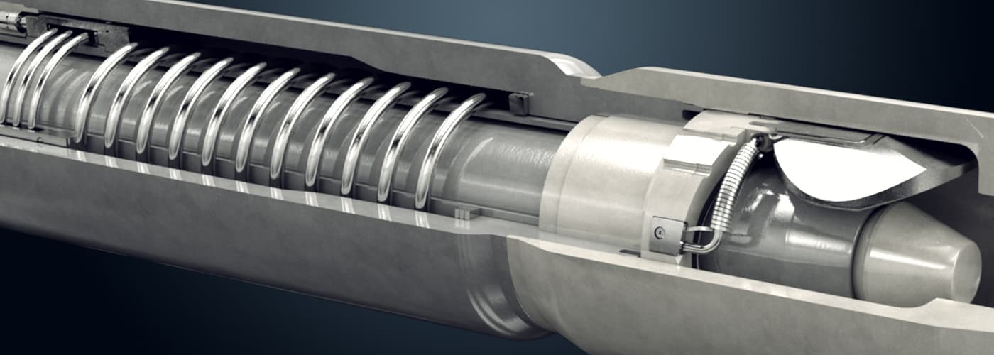
Through decades of innovation and experience, Schlumberger safety valve flapper systems are proven robust and reliable. The multizone dynamic seal technology for hydraulic actuation of subsurface safety valves is a further improvement in reliability performance when compared with traditional seal systems in the industry.
The multizone seal technology is currently available in the GeoGuard high-performance deepwater safety valves, which is validated to API Spec 14A V1 and V1-H.
Baker Hughes’s portfolio of subsurface safety valves deliver reliable performance when it matters the most, providing emergency closure in the event that well control is lost. We offer a full range of valves to suit applications ranging from shallow- to deep-set, and the valves are available in surface- and subsurface-controlled, tubing-retrievable, and wireline-retrievable options. All Baker Hughes valves undergo stringent prototype testing and conform to standards and specifications such as API and ISO, as well as requirements requested for your unique situation.

Tejas has positioned itself as a Technology Partner to provide turnkey product solutions to OFSC’s and since 1999 developed exclusive products and complete product lines for OFSC’s. We are deeply rooted in Research & Development (R&D) with deep expertise in downhole completions products, especially subsurface safety valves and other flow control devices.
Designed to provide protection from well-control events, Superior surface-controlled subsurface safety valves are built and tested to the highest API standards. Our field-proven line will allow you to quickly close a well when needed, protecting assets and people. Available in sizes from 2-3/8” to 7”, our retrievable safety valves are designed for setting depths of up to 3,000 feet and pressures of up to 10,000 psi.
Halliburton provides proven, high-performance tubing-retrievable and wireline-retrievable subsurface safety valves (SSSV) designed to reliably shut-in (fail safe) if a catastrophic event occurs, allowing operators to maintain safe operations.

The TSS series subsurface safety valves are tubing retrievable surface controlled subsurface safety valves. Compared with the TS series, the safety valve features super slim outer diameter design. The control line connects the valve to the surface, and the pressurization from surface on the control line controls the opening and closing of the flapper. This series of products includes self-equalizing and non-equalizing types.
Aberdeen-based oil and gas production technology business Pragma said it has developed an advanced downhole safety valve to create an improved well control solution for cable deployed Electric Submersible Pumps (ESPs) retrofitted to production wells.
The new valve will enable on and offshore installations to meet all safety regulations while improving the operational footprint at the wellsite during installation and retrieval by reducing time, cost, personnel and risk.
An API 14A qualified subsurface safety valve (SSSV) is a legal requirement for producing wells in many regions. These devices generally use a flapper style mechanism and are incorporated in the production tubing during completion. However, when an ESP is retrofitted to a well, its surface control lines run through the inside of the production tubing, obstructing the SSSVs and creating the requirement for an additional safety valve. A rig would usually be mobilized to deploy the valve and then the ESP in separate runs, however cable deployment now provides significant cost and efficiency savings.
Pragma said its ESP safety valve has been designed to complement this type of deployment. It is a compact device, integrated within the lower portion of the ESP assembly and is deployed and retrieved through the production tubing in the same run as the ESP. It is the only device on the market which offers wellbore closure below the ESP control lines, the developer said. By installing the valve between the ESP and ESP packer, the valve does not rely on the integrity of aged well completion components unlike alternative systems.
The valve’s functionality is based on a novel pressure differential, or lift actuated design, requiring no pressurized chambers, hydraulic control lines or electrical power, which safeguards reliability. The valve will fail-safe close when the ESP is switched off and can be opened and closed as many times as required. The technology can also be applied to alternative artificial lift systems including capillary strings, gas lift velocity strings, progressive cavity pump and jet pump systems. A high temperature version is also available.
Pragma Technology Manager, Matt Manning, said, “Like a demand valve, or pressure regulator between the tank and mouthpiece of deep-sea diving equipment, our valve uses the ESP’s lifting capability to open or close it in line with production. The unique design advantages of this technology, combined with its compact nature, not only provide greater safety and reliability assurances to the operator, but also lower installation, operation and retrieval costs. The technology has been developed in-house and we are conducting prototype testing, with field trials and API 14A certification planned later this year.
“As the oil and gas industry continues to evolve, it’s important the supply chain also adapts to deliver quality solutions to support cost reduction and production optimization. The ESP safety valve is just one example of how Pragma continues to pioneer advanced technologies to deliver safety and efficiency gains.”

SSSV: Subsurface Safety Valve: a valve installed in the tubing down the well to prevent uncontrolled flow in case of an emergency through the tubing when actuated. These valves can be installed by wireline or as an integral part of the tubing. Subsurface Valves are usually divided into the following categories.
SCSSV: Surface-Controlled Subsurface Safety Valves: SSSV which is controlled from the surface and installed by wireline or as an integral part of the tubing.
SSCSV (storm choke): Subsurface-Controlled Subsurface Safety Valve: SSSV which is actuated by the flow characteristics of the well, and is wireline retrievable.
ASV: Annulus Safety Valve: a valve installed in the well to prevent uncontrolled flow in the casing-tubing annulus when actuated. It consists of an annular safety valve packer with a by-pass. The opening in the by-pass is controlled by a safety valve, which can be an integral part of the packer on a wireline retrievable valve.
The tubing safety valve is installed to provide a flow barrier in the production tubing string, between the tail pipe and the surface or mudline. Such a valve consists of 3 main items:
Safety valve should not be considered as an extra barrier in the tubing when the well is closed-in for a long period of time. Sealing is not optimal because of design space limitations. They should not be used to regularly shut-in the well.
The annulus safety valve (ASV) provides a flow barrier in the casing-tubing annulus. It consists of an annular safety valve packer with a by-pass. The opening of the by-pass is controlled by a safety valve, which can be an integral part of the packer or a wireline retrievable valve. It is a surface controlled, fail-safe closed device for annular flow.
In general, the ASV is installed in gas lifted wells where the annulus is filled with compressed gas and serves as a barrier. Because of gas lift valves, the tubing cannot be considered as a barrier between the reservoir and the surface. Although the gas lift valves are commonly equipped with check valves, they are not a valid barrier. The ASV is normally located at a shallow depth to reduce the volume of the gas stored in the annulus between the ASV and the wellhead.
The valve body and connections should be at least as strong as the tubing. It should provide leak resistance to internal and external pressures and be compatible with the fluids.
During the installation of the tubing string, it is necessary to keep the valve open. This can be done by inserting a retrievable lock-open tool in the valve, without or in combination with the control signal from surface.
Multiple zone completions, where wireline jobs are frequent on equipment installed beneath the safety valve. The larger bore of a TR-SSSV facilitates the operations, where a WR-SSSV normally has to be retrieved.
The wireline retrievable safety valve (WR SCSSV) is run on wireline. A lock mandrel is screwed on top of the WR SCSSV that enables using a landing nipple. This nipple must hold the valve/mandrel assembly against pressure differentials loads. The nipple has a polished bores to seal the path between WR SCSSV and landing nipple by seals fitted to the outside of the valve/mandrel assembly.
With hydraulically operated WR SCSSVs, the external seals have also the function of containing the control fluid that is to be transmitted to the valve actuator.
The landing nipple for an electrically operated valve has a connection for an electric control line and an inductive coupler to transmit the signal to the WR SCSSV.
Trough Flowline retrievable safety valves use specially constructed mandrels and landing nipples. They must have a stronger hold-open force than SCSSVs, because the Trough Flowline tools are circulated upwards in the tubing string, which tends to drag the valve"s flow tube up, causing the valve to close. To overcome this problem the actuator hold-open force should be higher than the sum of the normal hold open force and the drag forces that can be experienced. Trough Flowline retrievable SSSVs can be used for subsea completions where wireline operations are difficult.
Another application is to install a SSSV in tubing without a landing nipple. Such a system consists of a production packer with an integral safety valve. The assembly is positioned by the coiled tubing and the packer is set by pressure from the coiled tubing.
Subsurface controlled valves are normally open and are designed to close with an abnormal change in well condition. They detect the flow or well pressure and close when the set limit is reached. Basically there are three different concepts:
Surface controlled valves utilise valve elements that are normally closed. This fail-safe mode requires that the valve is to be opened by a hydraulic control-line pressure. Loss of this pressure will result in the closing of the valve by a spring. The hydraulic pressure is supplied from a surface control panel to the valve and acts on the actuator. Typical for hydraulic operated SCSSVs is the hydrostatic head pressure, generated by the vertical column of control fluid, which additionally acts on the valve actuator.
the surface control line pressure and the time for valve operation will give an indication whether the valve opening and closing performance is satisfactory;
TR-SCSSVs of which the hydraulic actuator is damaged can be put back into function by inserting a back-up valve (insert valve), which can be operated with the existing hydraulic control system;
Electrically operated SCSSVs have in common with hydraulic SCSSVs that the differential pressure over the closed valve must be equalised before the valve can be opened and a means to keep the valve open must be permanently available from surface for fail safe operation.
With electric valves that means is an electrical signal, either dc or ac. Loss of this signal will result in closing of the valve. The force to close is always provided by expanding steel springs, which are precompressed by either electric power or by the well pressure.
One type of mechanically operated SSSV is the Go-Devil valve from Otis. This safety valve is a normally open valve. It is designed to close by an impact force on the head of the valve, provided by a heavy ball that is dropped from a ball-dropper assembly at surface. The impact force will activate the spring based mechanical linkage, that moves the valve to the closed position.
The ball-dropper assembly is flange mounted on top of the Christmas tree. The pocket of the ball dropper retains the ball, sized to activate the Go-Devil SSSV by falling against flow and impacting the head of the valve. The ball dropper assembly retains the ball until the loss of the control signal activates the release mechanism.
Three types of valve closure elements are commonly used for SSSV: the ball, the flapper and the poppet type. The flapper valve can further be divided in flat, contoured and curved flappers, while the poppet valve can be divided into closed body and sleeve type poppet valves. All types of closure elements pinch off the fluid stream by a pair of opposing surfaces rather than sliding surfaces. This principal method has the advantage that it can provide a good tight shut-off when the sealing surfaces are sound.
As noted the flapper valves may be flat, curved or contoured. The latter two were introduced to obtain a better OD/ID ratio, as they are shaped to fit when in the open position, more efficiently in the annular space of the valve housing.
The seat angle is the shape of the flapper sealing surfaces, which is an important parameter of the valve sealing performance. Traditional flapper valves have a seat angle of 45°, as the angled seat has the advantage that:
Due to the characteristics of the curved flapper design the seat angle may vary from 0° to 60° along the flapper circumference, thus requiring stringent alignment of the sealing faces. The contoured flapper design has an angled sealing surface over the full circumference of the flapper and thus has potential to provide good sealing. Field experience indicate that the flapper valve type is more reliable than the ball valve type.
When a SSSV is closed, a high differential pressure may be present across the valve closure element. Opening the valve under this condition will be difficult, if not impossible, because of the incapability of the relatively small valve mechanism to cope with the load working on the large diameter closure element. Insufficient equalising will introduce high loads that could deform critical valve parts. Also, erosive wash-out on the closure element by the sudden rush of well fluid through the partly opened valve can occur. Therefore, prior to opening a SSSV it is necessary to equalise the differential pressure.
The depth at which to set the subsurface safety valve depends upon a number of variables, such as hydrate and wax formation tendencies, deviation kick-off depth, scale precipitation, earthquake probabilities, etc. The OD of the safety valve may influence the casing/tubing string configuration and should be addressed at the conceptual design stage.
For tubing safety valves it is obvious that the deeper the valve is set (closer to the hydrocarbon source) the more protection it will give to the completion. However, the application of a deep-set tubing SSSV generates some unfavourable conditions, namely:
the higher temperature further downhole effects the reliability and the longevity of non-metal valve parts, for instance polymeric seals in hydraulic valves and electric/electronic parts in electric valves;
the hydrostatic head pressure generated by the hydraulic control-line column will generate excessive forces on the valve operating mechanism. Hence, designing and manufacturing of these valves becomes more complicated.
Furthermore, the required control pressure to operate a single control line valve (the majority of SSSVs) could become too high and more than the pressure rating of standard well completion equipment.
The approach for determining the required hydraulic control pressure at surface to hold a valve open depends on the type of valve, viz. the single control line valve, the dual control line valve and the valve with a pressure chamber.
Due to friction in the valve mechanism and the spring characteristic, there is a certain spread between the valve opening pressure (Pvo) and closing pressure (Pvc).
To ensure that the valve is completely open, a safety factor or pressure margin (Pm) is added to the surface control pressure. Hence, the available control pressure at surface to open the valve must be at least:
The dual control line valve or the pressure balanced valve uses a second control line from surface to balance the generated hydrostatic head pressure in the control line. The forces acting to operate this type of valve are as follows:
Due to friction in the valve mechanism and the spring characteristic, there is a certain spread between the valve opening pressure (Pvo) and closing pressure (Pvc).
When the valve is in the fully open position and the control and the balance line are both filled with fluid of the same fluid gradient, the following force equilibrium exists:
To insure that the valve is completely open, a safety factor or pressure margin (Pm) is added to the surface control pressure. Hence, the available control pressure at surface to open the valve must be at least:
The dome charged valve uses a pressure in an integral dome to (partly) balance the generated hydrostatic head pressure in the control line. The forces acting to operate this type of valve are as follows:
Due to friction in the valve mechanism and the spring characteristic, there is a certain spread between the valve opening pressure (Pvo) and closing pressure (Pvc).
To ensure that the valve is completely open, a safety factor or pressure margin (Pm) is added to the surface control pressure. Hence, the available control pressure at surface to open the valve must be at least:
The theoretical maximum setting depth of a single control line SSSV depends on the capacity of the valve closing spring to overcome the generated hydrostatic head pressure in the control line. For fail safety it is essential that the tubing pressure is not taken into account for the assistance of valve closing, even though single control line valves are assisted by this pressure. Hence, the governing factors for the maximum valve setting depth are:
* For fail safety, the worst case must be assumed, one in which the control line ruptures near the valve and annulus fluid will enter the control line. Therefore, for any completion the heaviest fluid gradient, either from the control fluid or from the annulus fluid, is used as the minimum control line fluid gradient.
Because the hydrostatic head pressure in the control line is counteracted, the setting depths of the dual control-line and the dome-charged valves are theoretically not limited.

Downhole Safety Valve is an integral part of Well Integrity Mangement System and acts as a failsafe equipment to prevent uncontrolled release of reservoir fluids. Periodic inspection and maintenance of downhole Safety Valve is essential under normal service conditions. Each Downhole Safety Valve should be tested and lubricated at specified regular intervals as recommended by ADNOCs Standard Operating Procedure and as dictated by field experience. Since it is a Critical Safety Equipment, preventive maintenance of Wireline Retrievable type downhole Safety Valve is being carried out annually which involves valve retrieval, leak/function test and redressing if required.
Current practice within ADNOC Onshore is to carry out redressing with third party for all Wireline Retrievable Safety Valve annually or in case they are observed to be passing (not meeting the maximum acceptable gas leak rate of 15 scf/min for gas and 400 cc/min for liquid) or do not pass function test carried out during 6 monthly and yearly Preventive Maintenance Schedule.
The cost incurred for third party redressing is substantial and can be optimized by evaluating the possibility of carrying out redressing in-house with available resources and using Original Equipment Manufacturer redress kit in situations where internal leak is not observed in the valve and valve can be redressed without the need to open tension spring and flow tube which requires extensive redressing setup available with third party.

This course introduces the purpose, operation, and application of Subsurface Safety Valves. Case studies demonstrate the need for setting the valves at certain depths. Environmental complications encountered in sub-sea installations, arctic conditions, extreme temperatures, and even earthquake-prone regions are covered. Surface and subsurface controlled downhole safety valves are described, accompanied by detailed animations and graphics demonstrating the valves’ operation. Students operate a surface control panel and see the effect of each action downhole.
Identify and describe the functions of the various components of a safety valve. *A one-year SkillGRID subscription is required for all new users, billed at $12/year.

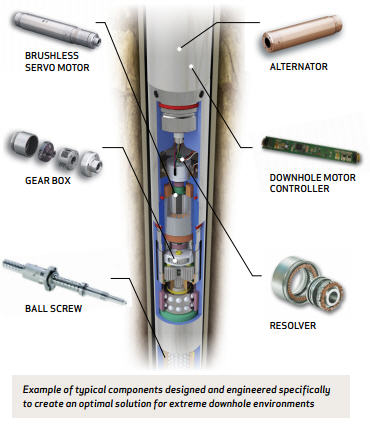
"We have a programme to take a proven electric actuator and bring it together with our DepthStar valve that is now running commercially using hydraulic power," says Halliburton product manager Tom Swan.

The invention relates to a downhole safety valve for a subterranean well, and more particularly to a safety valve utilizing electrical mechanism, controlled from the surface by electromagnetic waves, for opening and closing the valve and for locking the valve in an open position.
The employment of a downhole safety valve is well known for subterranean oil and gas wells. Such valve, which can comprise a plug or poppet type, a sleeve valve, a flapper valve, or a ball valve, is normally positioned downhole to close the bore of the tubing string leading from one or more production zones to the well surface. Such safety valves are normally biased to a fail safe condition, i.e., energized means will shift the valve to its closed position upon any significant reduction in the opening force applied to the valve structure.
The more common type of safety valves utilizes a control fluid pressure to effect the shifting of the valve to its open positon. Such control fluid pressure is supplied through a small control conduit which is run into the well concurrently with the production tubing. Necessarily, such conduit is susceptible to damage during the run-in process, or joints in the conduit may develop leaks. In any event, the loss of integrity of the conduit will effect the immediate closing of the safety valve and the well is essentially out of operation until the entire tubing string has been pulled from the well and the necessary repairs made.
To offset the difficulties involved in the utilization of a control pressure conduit, it has been previously proposed that the downhole safety valve be actuated from its closed to its open position by a downhole solenoid which is supplied with electrical power from the surface by an electric line. The same problem of potential damage to the electric line during the run-in process exists with this arrangement and, of course, any abrasion of the insulation of the electric line during the run-in process leads to the possibility of short circuits developing in the electric line, again requiring that the entire tubing string be pulled from the well to effect the necessary repairs.
It is often necessary to run tools down through the production conduit and the open downhole safety valve to effect treatment of the production formation. Under such conditions, it is highly desirable that the safety valve be positively locked in an open position so that unexpected fluctuations in well pressure will not cause the safety valve to attempt to close when a wireline or a treatment conduit is passing through the valve. A variety of fluid pressure or mechanically actuated latching mechanisms have heretofore been proposed to effect the locking of a downhole safety valve in an open position. U.S. Pat. No. 4,579,177 discloses a solenoid actuated locking mechanism for a downhole safety valve. Such solenoid is energized by an electric line leading to the well surface, hence is subject to the problems mentioned above involved in maintaining the integrity of an electric line run into a subterranean well concurrently with production tubing.
There is a need, therefore, for a subsurface safety valve which is controllable from the surface to move from a closed to an open position, and also incorporates a locking mechanism, controllable from the well surface, for selectively maintaining the safety valve in a locked-open position, which does not depend upon the utilization of a control fluid pressure conduit or an electric line extending from the safety valve to the well surface to effect its operation.
In co-pending application, Ser. No. 730,397, filed May 3, 1985, and now U.S. Pat. No. 4,736,791, entitled "Improvements in Subsurface Device Actuators," and assigned to a wholly owned subsidiary of the assignee of the instant application, there is disclosed a system for actuating a downhole safety valve between open and closed positions in response to low frequency electromagnetic waves received by a downhole antenna from a surface located transmitting antenna. Such apparatus incorporates a downhole battery but does not employ the battery for effecting the shifting of the safety valve from its closed to its open position, an act which requires a substantial amount of electrical energy. Instead, the system disclosed in such application relies upon fluid pressure to effect the shifting of the safety valve from a spring bias closed position to an open position.
Such co-pending application does, however, disclose a downhole battery and a locking solenoid selectively energized by such battery in response to electromagnetic wave signals generated by a surface transmitter. The energization of the solenoid effects the operation of a locking mechanism to secure the safety valve in its open position. Thus, while some of the disadvantages of the above described prior art systems have been overcome, the construction disclosed in the aforesaid pending application still requires the utilization of fluid pressure to effect the shifting of the safety valve to an open position.
This invention provides a downhole safety valve in a subterranean well, which has an axially shiftable actuator which is moved by an electric motor driven drive mechanism between opening and closing positions of the safety valve. The safety valve may comprise any one of the well known types, namely, a poppet valve, a sleeve valve, a flapper valve, or a ball valve, the only requirement being that such valve be capable of being opened by axial movement of an actuator. The electric motor for effecting the axial shifting of the actuator is energized by a downhole battery and the energization of the motor to rotate in either direction is selectively controlled by electromagnetic wave signals generated at the well surface.
Additionally, this invention provides a locking mechanism for effecting the locking of the safety valve in its open position. Such locking mechanism is actuated by the battery energization of a solenoid. Again, the selective energization of such solenoid is controlled by electromagnetic waves transmitted from the well surface.
Moreover, the apparatus of this invention preferably employs a fail safe means to effect the return of the safety valve from its open to its closed position, thus eliminating any drain on the battery to effect the closing stroke of the valve. The only energy required to maintain the valve in its locked open position is that required by the solenoid which is minimal, due to the fact that the armature of the solenoid only has to retain a relatively light weight latch retaining sleeve in engagement with collet arms which are lockingly engaged with the actuator for the safety valve. Thus, the necessity of providing a continuous high current to maintain the safety valve in an open position has been eliminated.
Lastly, a pressure equalizing mechanism is provided for the safety valve which is actuated by the initial axial movement of the actuator from its valve closing position.
Thus, the method and apparatus of this invention provides a conveniently controllable downhole safety valve which may be selectively opened or closed by electromagnetic waves transmitted from the well surface and eliminates the necessity of running either control fluid conduits or electric wires into the well solely for the purpose for controlling the operation of the safety valve.
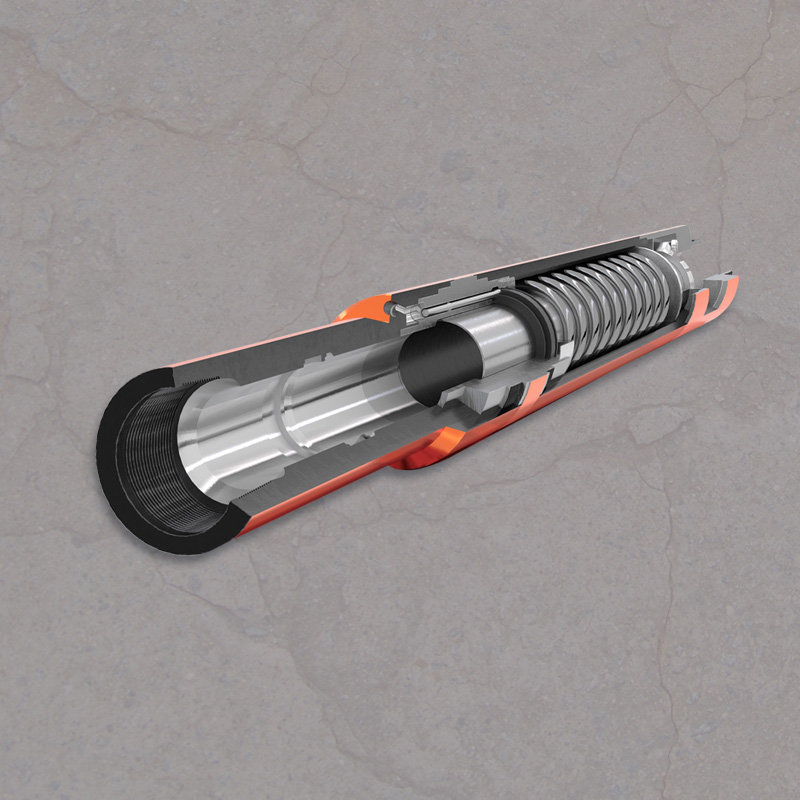
FIG. 1 is a schematic vertical sectional view of a safety valve embodying this invention shown in its installed position within a production conduit of a subterranean well.
FIGS. 2A, 2B, 2C, 2D, 2E, 2F, 2G, 2H, 2I, 2J, 2K and 2L collectively constitute a schematic vertical sectional view illustrating the detailed construction of a safety valve embodying this invention installed in a subterranean well, with the elements of the safety valve shown in their closed position.
FIGS. 3A, 3B, 3C, 3D, 3E, 3F, 3G, 3H, 3I, 3J, 3K, and 3L are views respectively similar to FIGS. 2A, 2B, 2C, 2D, 2E, 2F, 2G, 2H, 2I, 2J, 2K and 2L but showing the elements of the safety valve in their locked open position.
FIG. 5A is a sectional view of a safety valve embodying this invention and incorporating a pressure equalizing feature with the valve in its closed position.
Referring first to the schematic view of FIG. 1, a housing 10 for a safety valve embodying this invention is shown installed in the bottom end of production tubing 2 which is run into a well casing 1. The annulus la between the production tubing 2 and the well casing 1 is sealed by a conventional packer 3. The safety valve housing 10 may be suspended in the bottom end of the production tubing string 2 by any type of conventional latching mechanism 5 which cooperates with an internal recess 2a formed in the production tubing 2.
Safety valve housing 10 incorporates a safety valve mechanism 11, a battery case 12, and an electronic signal converter unit 13. An antenna housing 15 is flexibly connected to the bottom end of the safety valve housing 10 by a conventional flex joint 14 and houses an antenna 16. The antenna housing 15 is maintained in a fixed axially aligned position relative to the axis of casing 1 by a pair of stabilizing units 17 respectively mounted at either end of the antenna housing 15.
As best shown in the schematic circuit diagram of FIG. 4, a surface mounted electromagnetic wave transmitter 18 transmits an electromagnetic signal downwardly through the earth which is received by antenna 16 and supplied to an electronic receiver unit 13. The transmitter 18 and receiving antenna 16 may be of the type described in said co-pending application Ser. No. 730,397. Electronic unit 13 receives and amplifies the received signal and supplies it to a central processor unit 6. Processor 6 in turn controls the supply of energy from the batteries in battery case 12 to a motor 30 for effecting the shifting of a safety valve actuator 20 between open and closed positions. Additionally, the processor unit 6, in response to a second signal carried by the electromagnetic waves generated by transmitter 18 selectively applies energy to a solenoid latch 40 (hereinafter described) to selectively effect the locking of the safety valve 11 in an open position.
Referring specifically to FIGS. 2A and 2B, the safety valve housing 10 is secured within the bottom end of production tubing string 2 by a conventional latching mechanism 5 including a tubular latching body 50 in which are mounted a plurality of peripherally spaced, radially shiftable latching dogs 52 which are respectively held in engagement with an internal recess 2a in production tubing 2 by a wireline actuated sleeve 54. When the latch 5 is engaged, the sleeve 54 is secured to the body 50 by a C-ring type locking ring 56. Additionally, an external seal 58 is provided on the lower portions of the latching mechanism 5 to provide sealing engagement with the bore 2b of the production tubing string 2. Since the latching mechanism 5 is entirely conventional, further description thereof is believed unnecessary.
A conical valve head 102 forming part of a plug-type valve unit 100 sealably engages the non-elastomeric seal element 216 to achieve a closing of the bore of the latching mechanism 5, thus closing the bore 5a of the production tubing string 2. The conical valve head 102 is secured by internal threads 103 to the top end of a rod-like actuator 104, and actuator 104 is spring biased by a spring 226 (FIG. 2C) to the closed position of the valve head 102 relative to the annular seal 216, as will be later described in detail. A set screw 105 secures the threaded engagement between valve head 102 and actuator rod 104. Below the annular seal 216, the seal retaining sleeve 220 is provided with a plurality of peripherally spaced, inclined, radial ports 223 which provide for free communication between the tubing casing annulus 1a and the bore 5a of latching mechanism 5 when valve head 102 is shifted downwardly to its open position, as shown in FIG. 3B.
provided on the inner surface of spring housing 230 and the downwardly facing end surface of an annular plug 233 which is secured to external threads 235 formed on the top inner surface of the spring housing 230. Thus, the actuator rod 104 for the valve unit 100 is slidably and sealably mounted in the tool for axial movements relative to the annular valve seat 216 and is held in a fail-safe closed position by the power spring 226.
The motor mounting sleeve 240 extends downwardly a substantial distance, and, at its bottom end, shown in FIG. 2E, supports a fluid submersible reversible electric stepping motor 260 which is only shown schematically. Motor 260 has an externally projecting mounting flange 261 which is secured to the motor mounting sleeve 240 by a plurality of peripherally spaced, radially disposed bolts 242.
The top end of the actuating sleeve 292 is provided with internal threads 296 which engage external threads provided on the lower rod portion 112 of a force transmitting collet 110. The upper end 113 of the collet 112 is of tubular configuration and is provided with a plurality of peripherally spaced, flexible arm portions 114, each of which teminates in an inwardly enlarged head portion 116 (FIG. 2C). The head portions 116 are normally disposed below an external locking rib 120 formed on the exterior of the actuating rod 104 when such rod is in the closed position of the valve as shown in FIG. 2C. Upward movement of the collet 110 will produce an engagement of the collet heads 116 with the locking rib 120 and hence permit the actuating rod 104 to be pulled downwardly by downward movement of the collet 110 produced by the actuating sleeve 292, as shown in FIG. 3D.
Immediately above the top end of the actuating sleeve 292, a fluid immersible, electric solenoid 130 is mounted. Such solenoid is shown only schematically and is provided with a ferromagnetic annular armature 132 which has an upwardly extending sleeve portion 134 provided with internal threads 136. A latching sleeve 140 has external threads provided on its bottom end cooperating with internal threads 136 and defines an internally projecting, downwardly facing spring seat 143. A relatively light compression spring 150 is compressed between spring seat 143 and an external shoulder 115 provided on collet 110. Thus, the locking sleeve 140 and the armature 132 are biased to an upward position relative to the solenoid 130. When the solenoid 130 is energized, the armature 132 will be shifted downwardly into engagement with the top end of such solenoid and this downward axial movement of the latching sleeve 140 moves a latching head 142 (FIG. 2C) secured to the top end of latching sleeve 140 into abutting engagement with the outer walls of the collet arms 114, thus securing the collet locking heads 116 in engagement with the locking rib 120 provided on the actuating rod 104. This assumes, of course, that the electric motor 260 has been energized to rotate first in a direction to bring the collet latching heads 116 upwardly to a position above the locking rib 120 on the actuator rod 104. It will be noted that a stop ring 107 is secured to the external periphery of actuator rod 104 by set screws 109 to limit the upward movement of the actuating collet 110. It should also be noted that the solenoid 130 moves upwardly with the collet 110, thus not affecting the position of the latching sleeve 140 relative to the collet locking heads 116 until solenoid 130 is energized.
The operation of that portion of the mechanism 11 of the safety valve 10 heretofore described will be readily apparent. Assuming that the safety valve is in its normal closed position, the electric motor 260 is energized from a suitable source of electricity, preferably a downhole battery, as will be described, to move the collet 110 upwardly and thus position the collet locking heads 116 above the locking rib 120 formed on the actuator rod 104. When the motor stalls out due to contact of the latching sleeve with the stop ring 107, an electrical signal will be generated which will effect the de-energization of the electric motor 260. The electric motor 260 is then energized to rotate in the opposite direction, thus bringing the collet 110 downwardly and engaging the latching heads 116 with the locking rib 120 on the actuator rod 104. Concurrently therewith, the solenoid 130 is energized, thus moving the ferromagnetic armature 132 downwardly and effecting a downward displacement of the latching sleeve 140 relative to the collet 110 to bring the latching head 142 into abutting engagement with the collet locking heads 116, thus securing the locking heads to the actuator rod 104 and assuring that the actuator rod 104 will be moved downwardly to the open position shown in FIG. 3D. The electric motor 260 may be de-energized without affecting the position of the actuator rod 104 since it is locked in position by the locking sleeve 140. Subsequent de-energization of the solenoid 130 will permit the armature 132 to be moved upwardly by the spring 150 and this will move the latching head 142 out of abutting engagement with the collet locking heads 116, permitting such collet locking heads to release from the locking rib 120 on the actuator rod 104, hence permitting the actuator rod 104 to be driven upwardly by the power spring 226 to return the valve head 102 to its closed, sealed position with respect to the annular seal 216.
In the preferred embodiment of the invention, the energization and de-energization of the electric motor 260 and the latching solenoid 130 are respectively controlled by electromagnetic wave signals transmitted from a surface transmitter and received by the downhole antenna 16. FIGS. 2E, 2F, 2G, 2H, 2I, 2J, 2K and 2L indicate the preferred apparatus for effecting the energization and control of these downhole electrical elements. To minimize friction, and to provide a noncorrosive environment, the motor 260, the gear box 270, the ball nut screw 280, the ball nut 290 and all of the valve actuating structure thereabove, up to the seal unit 225 (FIG. 2B), are preferably surrounded with an appropriate oil having both lubricating and insulating properties. A seal 256 (FIG. 2F) at the bottom of main housing 250 and seal 241 (FIG. 2C) at the top of main housing 250 cooperate with seal assembly 225 to provide a chamber for such oil which may be inserted through a plugged hole (not shown). Such oil will undergo a substantial expansion due to temperature change as the mechanism is lowered into the well. For this reason, a pressure compensating cylinder 300 (FIG. 2E) is mounted in the lower end of the main housing 250. Cylinder 300 has an upper end cap 302 secured thereto by threads 303 and having a plurality of axially extending holes 304 extending therethrough to permit the lubricating fluid to freely enter the interior of the pressure equalizing cylinder 300. A conventional piston 306 is slidably and sealably mounted within the bore of the pressure compensating cylinder 300. The lower end of cylinder 300 has a pipe 310 (FIG. 2F) sealably secured thereto and communicating with a bore 322 provided in a connecting sub 320, which bore extends to the casing annulus 1a. Since the connecting sub 320 is threadably secured to internal threads 254 provided in the bottom end of main housing 250 and the threaded connection is sealed by seal 256, it will be apparent that any increase in fluid pressure within the space defined by the main housing 250 will result in a downward displacement of the pressure compensating piston 306 and the pressure is relieved by exhausting well fluid below the piston 306 through the conduit 322 to the casing annulus.
The bottom end of the electronics module 360 is provided with an end cap 362 and such end cap is connected by a conventional flexible or universal joint 370 to the top end of a housing 402 forming part of a stabilizer unit 400. Stabilizer unit 400 is shown and described in detail in co-pending application Ser. No. 164,867, filed concurrently herewith and assigned to the assignee of the instant invention. Such disclosure is hereby incorporated in this application by reference and will not be described in detail. In the run-in position of the stabilizer unit 400, a plurality of peripherally spaced, radially expandable linkages 406 are provided on housing 402. Each linkage 406 mounts a pair of axially spaced anti-friction rollers 404 which are held in a radially retracted position as shown in FIG. 2H, during run-in. Such linkage is expanded to a radially expanded position by the melting of a fusible pin 408 which is meltable when exposed to the well temperatures existing at the depth of insertion of the safety valve 10. When pin 408 melts, the rollers 404 move out to a radially expanded position under the bias of spring 410 and engage the bore wall of the well casing 1, as shown in FIG. 3H.
Referring now to FIG. 5, there is shown a modified safety valve embodying this invention which incorporates a pressure equalizing feature. Those skilled in the art will recognize that it is desirable that the fluid pressures existing above and below the valve head be equalized prior to effecting axial movement of the valve head relative to the annular seal. In FIG. 5, where similar numerals indicate parts similar to those previously described, the conical valve head 500 is not directly connected to the actuating rod 104 as in the previously described modification. Instead, the connection of valve head 500 is effected through a lost motion connection.
Thus, a lost motion connecting sleeve 510 is threadably secured to threads 103 on the top end of the actuator rod 104. Lost motion connecting sleeve 510 has an internally projecting rib 512 at its upper end which is engagable with an external rib 522 formed on a valve plug 520 which, in the closed position of the valve head 500 closes a small central bore 501 formed in such valve head. Valve plug 520 is urged to a closing position by a compression spring 530 which is compressed between the valve plug 520 and the top end of actuator rod 104. The lost motion connecting sleeve 510 is provided with an external rib 514 which, after limited downward movement of the actuator rod 104 sufficient to pull the valve plug 520 out of the bore 501 of the valve head 500 engages an internally projecting shoulder 542 formed on the end of a sleeve 540 which is secured to external threads 502 formed on the lower portion of the valve head 500. Additionally, the valve head 500 is provided with one or more radial passages 526 which provide a fluid connection between the valve head bore 501 and the casing annulus 1a through the inclined radial passages 223.
The operation of this modification of the invention will be readily understood by those skilled in the art. In the closed position of the valve illustrated in FIG. 5A, the bore 501 of the valve head 500 is closed by the valve plug 520 which is urged to its closed position by the compression spring 530. Initial downward movement of the actuator rod 104 will pull the valve plug 520 downwardly by lost motion sleeve 510 to open the bore 501 to fluid flow to the casing annulus, thus equalizing the fluid pressures above and below the valve head 500 before the valve head 500 is moved from its sealing engagement with the annular seal ring 216. Further downward movement of the actuating rod 104 will bring the external shoulder 514 on the connecting sleeve 510 into engagement with the internally projecting shoulder 542 on the sleeve 540 and effect downward movement of the valve head 500, thus completely opening the bore of the tubing string to communication with the casing annulus, as shown in FIG. 5B.
From the foregoing description, it will be readily apparent to those skilled in the art that this invention provides a unique mechanism for effecting the shifting of a safety valve, spring biased to a closed position, to an open position by a downhole electric motor energized by downhole batteries. The invention also provides a solenoid actuated latching mechanism for locking the safety valve in an open position, thus eliminating current drain on the batteries except for that required to hold the solenoid actuated latch in its collet engaging position. The current drain on the downhole batteries is thus significantly reduced.
It is also readily apparent that a surface source of electricity could be employed to effect the energization and de-energization of the downhole motor and the latching solenoid, and the invention is not to be construed as limited to use with a downhole battery as the source of energy.


 8613371530291