
electric downhole safety valve factory
Halliburton provides proven, high-performance tubing-retrievable and wireline-retrievable subsurface safety valves (SSSV) designed to reliably shut-in (fail safe) if a catastrophic event occurs, allowing operators to maintain safe operations.
Our downhole safety valves provide your testing operations with fail-safe sustained control downhole in the event of an emergency or to facilitate test procedures.
Surface-controlled subsurface safety valves (SCSSVs) are critical components of well completions, preventing uncontrolled flow in the case of catastrophic damage to wellhead equipment. Fail-safe closure must be certain to ensure proper security of the well. However, this is not the only function in which it must be reliable—the valve must remain open to produce the well. Schlumberger surface controlled subsurface safety valves exceed all ISO 10432 and API Spec 14A requirements for pressure integrity, leakage acceptance criteria, and slam closure.
Through decades of innovation and experience, Schlumberger safety valve flapper systems are proven robust and reliable. The multizone dynamic seal technology for hydraulic actuation of subsurface safety valves is a further improvement in reliability performance when compared with traditional seal systems in the industry.
The multizone seal technology is currently available in the GeoGuard high-performance deepwater safety valves, which is validated to API Spec 14A V1 and V1-H.
Baker Hughes’s portfolio of subsurface safety valves deliver reliable performance when it matters the most, providing emergency closure in the event that well control is lost. We offer a full range of valves to suit applications ranging from shallow- to deep-set, and the valves are available in surface- and subsurface-controlled, tubing-retrievable, and wireline-retrievable options. All Baker Hughes valves undergo stringent prototype testing and conform to standards and specifications such as API and ISO, as well as requirements requested for your unique situation.
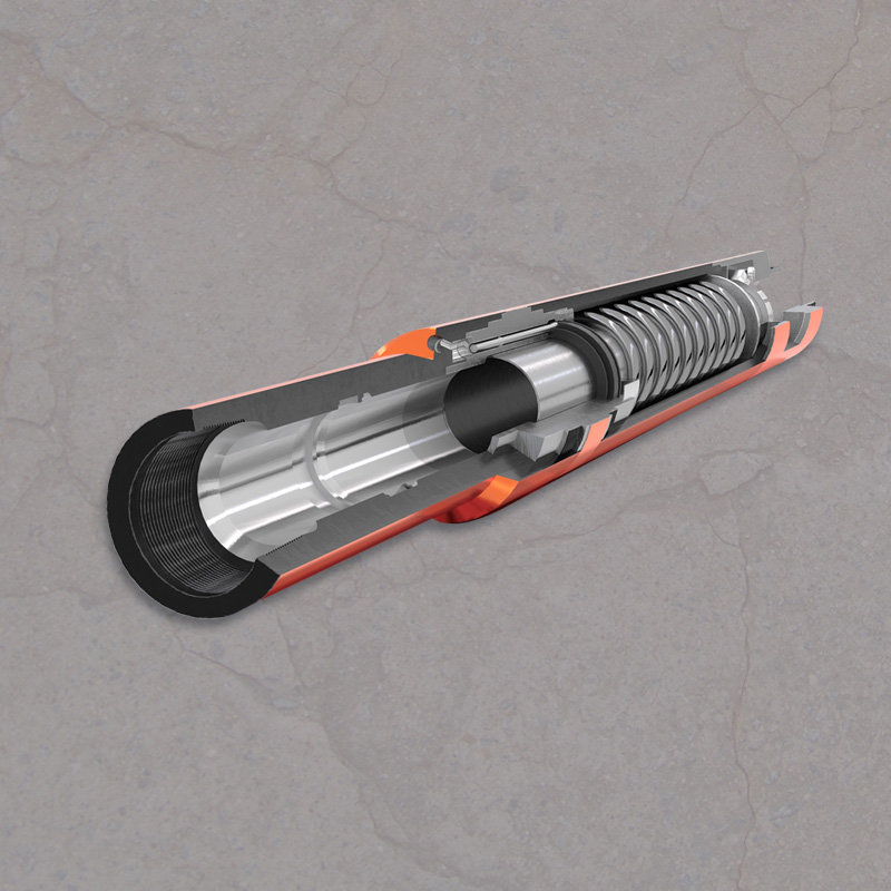
The tubing-retrievable subsurface safety valve (SSSV) provides well protection against pressure drop and system failure in wireline and thru-tubing operations. This retrievable safety valve is controlled from the surface with a hydraulic control line. The valve connects to the tubing string and remains open if adequate pressure is maintained. If pressure drops below the threshold (as occurs in the beginning stages of losing well control), the valve closes. This creates a barrier in the tubing to prevent fluids from rushing up the tubing.

The Flow Component Testing Facilities (FCTF) at SwRI are accredited through the American Petroleum Institute (API) to perform validation testing on both surface and subsurface safety valves. The facilities are also used to perform safety valve testing on other downhole safety valves, riser isolation valves, and wellhead valves. All testing is completed under an API Q1 and ISO 17025 quality management system.
SwRI performs SSSV testing on surface control safety valves (SCSSV) and subsurface control safety valves (SSCSV), subsurface injection safety valves (SSISV), and annular safety valves.Validation Testing – Annex B
SwRI performs testing on various types of valves used as underwater safety valves (USV), surface safety valves (SSV), and boarding shutdown valves (BDSV). This equipment is essential for emergency shutdown of offshore production.

Halliburton provides proven, high-performance tubing-retrievable and wireline-retrievable subsurface safety valves (SSSV) designed to reliably shut-in (fail safe) if a catastrophic event occurs, allowing operators to maintain safe operations.

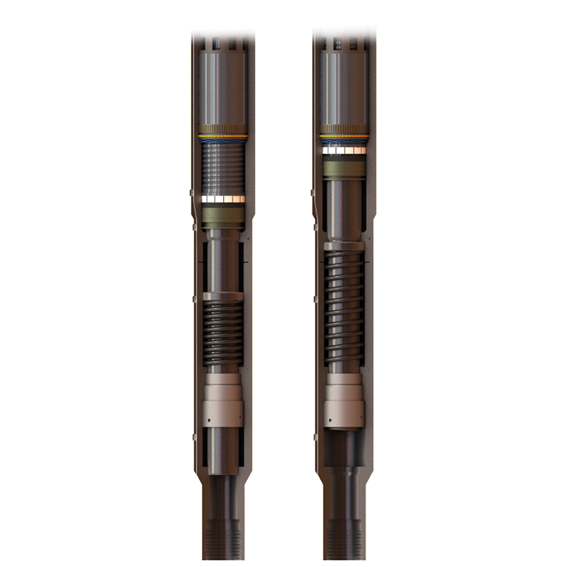
The TSS series subsurface safety valves are tubing retrievable surface controlled subsurface safety valves. Compared with the TS series, the safety valve features super slim outer diameter design. The control line connects the valve to the surface, and the pressurization from surface on the control line controls the opening and closing of the flapper. This series of products includes self-equalizing and non-equalizing types.

The pressure in either type of well may be considerable so the well has to be isolated by a well tree placed on the well head with valves to control the flow of fluids from or into the well. Well heads can be situated on land, on fixed or floating off shore platforms, or on the sen bed itself. These positions are vulnerable to external forces (fire, explosion, collision, snagging) which could damage the well head or well tree below the isolation valves or damage the valves themselves. This could open up the well with possible catastrophic results.
To prevent such an occurrence, self-closing valves may be placed down the well, both in :he production tubing and the annulus. They may be surface controlled sub-surface safety valves (SCSSV) or down hole safety valves (DHSV). The valves have springs so that they fail safe closed in an emergency and are kept open by hydraulic fluid pressure supplied through a relatively small bore tube. The use of hydraulic fluid pressure to operate the valves has a number of disadvantages:
3. Directly controlled DHSVs have to force the hydraulic fluid back up the line when they fail safe closed. This reduces the speed of closure and requires the valves to have large bulky springs.
Another disadvantage of hydraulically operated DHSVs is that the hydraulic lines have to pass through the well head or tree. Each fluid path below the valves of the tree is a potential leak path out of the well. Any failure of the DHSV seals or of the control line will result in the well pressure being exerted directly onto the hydraulic fluid exit ports and on to the control system. Extra tree fail safe valves must therefore be incorporated on each down hole control line.
One direct line is used to operate the valve, which means that the hydraulic pressure must exceed the maximum well pressure to open the valve. This has the disadvantage that a high pressure line is required.
The above-mentioned disadvantage of hydraulic operation of DHSVs can be eliminated by controlling the valves electrically. There are two aspects of electrical operation of down hole equipment, viz.
3. The use of electricity is relatively independent of distance and temperature. Thus DHSVs can be set deep down the hole thereby increasing well safety.
4. Once the electricity has been switched off, or if it fails, there are no residual forces remaining. Thus a fail safe closed valve will close faster, increasing the safety response to any malfunctions in the well.
1. Pressure sealed electric cable can be used through the well head and well tree into the well bore. There is no need for any fluid path below the well tree master valves.
The present invention is concerned with a mechanical actuator operated by electrical power suitable for actuating down hole equipment in a well, for example a down hole safety valve.
The actuator of GB 2216625A may be powered by a DC or AC electric motor and may be used for example for sub-sea valves of a sub-sea oil or gas production complex. The present invention may be considered as a development of the actuator of GB 2216625A designed specifically for actuating down-hole equipment.
The actuator of GB 2216625A and the present actuator may need to be primed to bring them to or restore them to their actuating positions, i.e. the rotatable sleeves may have to be capable of being rotated in both directions by the electric motor. The motor is thus preferably reversible and may conveniently be a DC Motor.
The end of the two-part drive sleeve farthest from the gear assembly may be screw-threaded and engage with screw threads of the actuating sleeve, so that rotation of the drive sleeve moves the actuating sleeve axially up or down the screw threads and hence moves the equipment, e.g. opens a down-hole safety valve against the force of its fail safe spring tending to keep it closed.
The releasable lock operated by a solenoid to lock the two-part sleeve against relative axial movement may be a collet engaging with a groove in the end of the two-part drive sleeve farthest from the gear assembly, e.g. adjacent the point where its screw thread engages with the screw thread of the actuating sleeve. The groove may be in a bearing bushing so that the drive sleeve can rotate while the collet and groove do not. The solenoid will thus hold the two part sleeve and actuating sleeve against axial movement, a relatively small current being capable of effecting this. Any failure of the electrical power supply or any deliberate switching off the power supply will release the lock thereby allowing the fail safe spring of the down hole equipment to act closing the equipment and moving the actuating sleeve and the actuation sleeve - disengaging part of the two-part drive sleeve axially.
The down hole equipment to be actuated may be any required piece of equipment, but may particularly be a down-hole safety valve. It may be a DHSV for the production tubing or for the annulus. It may thus be used in combination with an annulus down hole safety valve as described in UK Patent Application No 9017916.9.
The valve and actuating sleeve may have flow equalising ports and passages allowing the down hole pressures on either side of the valve to balance prior to the opening of the valve, thereby reducing the actuating force required to open the valve.
The left hand side of FIG. 1 shows the actuator of the present invention in its non-operational position and with the valve to be actuated closed. The right hand side of FIG. 1 shows the actuator operational, holding the valve open. This is for purposes of illustration only, it being understood that the drive sleeve and actuating sleeve of the actuator are cylinders.
In FIG. 1, upper mandrel 10 and lower mandrel 11 are inserted into the production tubing of a well just above the down hole equipment to be actuated. Surrounding and spaced from the mandrels is valve housing 12 enclosing an annular space between it and the mandrels. The annular space is closed at the top by plate 13 screw threaded onto upper mandrel 10 and valve housing 12 and having seals 14 to prevent fluid ingress into the annular space. The annular space is sealed at the bottom by valve housing 12 being screw threaded onto lower mandrel 11 and by seal 14A.
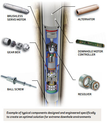
Within the annular space is a DC motor and mechanical actuator assembly. This assembly is formed, reading from the top downwards, of a brushless 24 V DC electric motor 15, harmonic drive gear 16, two-part drive sleeve 17, collet lock assembly 18 and solenoid 19. Actuating sleeve 20 is within the upper and lower mandrels 10, 11 spanning the gap between the mandrels. It has splines 49A engaging with splines 49B on lower mandrel 11.
Describing these main parts of the assembly in more detail, electric motor 15 may be of standard known design with armature or rotor 21 and stator or field-windings 22. Electrical power is supplied through pressure sealed cable 23 enclosed in steel tubing 24 with a screw threaded connector 25 where the cable passes through top plate 13. There is a junction box 26 in cable 23, splitting the power supply so that it goes both to motor 15 and solenoid 19. The power supply to solenoid 19 has its own pressure sealed cable 27 within steel tubing 28 passing down the outside of valve housing 12. A parallel line 28A for downhole gauges is run alongside the valve line 28.
Electric motor 15 drives harmonic drive gear 16, which may also be of known type and construction having a wave generator 29 driven by the motor, acting on a flexible splined band 30 within a circular spline 31. As previously explained the flexible band 30 engages with circular spline 31 at two points and rotation of the wave generator 29 will precess the two contact points around circular spline 31. A circular gear with 202 splines and a flexible band with 200 splines will move circular spline 31 two splines per rotation of wave generator 29, giving the gear assembly a mechanical advantage of 100:1.
Actuating sleeve 20 has seals 43 sealing it with respect to upper mandrel 10 and lower mandrel 11. These may be double seals, i.e. with one decompression resistant seal and one chemically resistant seal. Actuating sleeve 20 and lower mandrel 11 have a flow equalising system 44 of ports and passages, i.e. port 48 in sleeve 20 and passage 45 in lower mandrel 11, extending down to the down hole side of the valve to be actuated. Port 48 in actuating sleeve 20 is protected by double seals 46. Actuating sleeve 20 has springs 47 between it and lower mandrel 11, these springs tending to force the sleeve to its upper position.
The actuator may be assembled as shown on the left hand side with actuating sleeve 20 and part 33 of two port sleeve 17 in their upper positions. The valve to be actuated will be closed.
Bearing bushing 39 is well above finger collet 37. The first action of a valve opening sequence is to prime the actuator by passing DC current in one direction. Motor 15 is operated in a direction of rotation that moves two part sleeve part 33 and extension 36 down the screw threads of actuating sleeve 20 to the bottom of these threads. This position is not shown in FIG. 1 but the action will take extension 36 and bearing bushing 39 down to a level where the bearing bushing recess is opposite the top of finger collet 37. The DC current will also be going to the solenoid and with this direction of current, will assist spring 42 in keeping lock collet 38 in its up position. No other parts move and finger collet 37 will not enter the recess. The downward movement of extension 36 and bearing bushing 39 is limited by the top of lower mandrel 11. Rotation of the DC motor in this direction is then stopped.
To open the valve, a reverse DC current is sent to motor 15 and solenoid 19 pulls down lock collet 38 against spring 42 forcing finger collet 37 into the recess of bearing bushing 39. This locks the relevant parts. The solenoid remains energised and the motor 15 is now operated in the opposite direction of rotation to that of the priming. Bearing bushing 39 remains stationary holding the lock but extension 36 rotates forcing actuating sleeve 20 down the screw threads. Actuating sleeve 20 is prevented from rotating by its splines 49A engaging with the splines 49B of lower mandrel 11.
The first part of the travel of actuating sleeve 20 will bring its flow equalising port 48 into alignment with the passage 45 in lower mandrel 11. The actuating sleeve will have reached the valve but the differential pressure across the valve may cause the motor to stall. Once the pressure has equalised across the valve through the pressure equalising ports and passages the actuator will have sufficient power to push down on the valve so that further rotation of motor 15 moves actuating sleeve 20 down to open the valve. When the valve is fully open, extension 36 will be at the top of the screw threads of actuating sleeve 20 and the motor will stall.
Power supply is maintained to the solenoid 19 and so long as it remains energised then the valve will remain open with lock collet 38 holding finger collet 37 into its recess. This open valve position is that shown on the right hand side of FIG. 1.
Any deliberate or accidental shut off of power to the solenoid 19 will allow spring 42 to move lock collet 38 up releasing the lock. Spring 47 of actuating sleeve 20 will then move actuating sleeve 20, extension 36 and part 33 of two part sleeve 17 up, allowing the fail safe spring of the valve to operate and close the valve (i.e. the parts will be restored to the position shown on the left hand side of FIG. 1).
While the power required to rotate two part sleeve 17 and move actuator sleeve 20 may be fairly high, only relatively low power is required to keep solenoid 19 energised and hold the valve open. The current being supplied to both the motor and the solenoid can be monitored. Any variation in current required may be a sign of an incipient malfunction or a change in down hole conditions allowing preventative remedial action to be taken.
FIG. 2 is a section through a conventional production tubing down hole safety valve which can be actuated electrically using the actuator of FIG. 1. The figure is illustrative, since the left hand side shows the valve shut and the right hand side open.
FIG. 2 shows a tubing sub 50 inserted into production tubing just below the actuator of FIG. 1. Actuating sleeve 20 of FIG. 1 extends down within the tubing 50. The valve is a flapper valve of known construction having flapper 51 mounted on hinge 52 and having a powerful spring 53 tending to move it to the closed horizontal position. Hinge 52 and spring 53 are to one side of the valve body being fixed to the lower mandrel 11 by screw 54. Tubing sub 50 has an upper valve seat 55 held by retainer ring 56 and a lower stop 57 made of elastomeric material.
When the valve is closed (see left hand side of drawing) flapper 51 is forced onto seat 55 by spring 53. However, if actuating sleeve 20 is moved down as described with reference to FIG. 1 then flapper 51 is gradually pushed through 90° to the position shown on the right hand side of the drawing. The downward movement of actuating sleeve 20 is limited by elastomeric stop 57. If actuating sleeve 20 is released as described with reference to FIG. 1 it moves back up quickly allowing spring 53 to close the valve equally rapidly.
The valve itself is of the type described in UK Patent Application No 9017916.9. Hydraulic operation of the valve is specifically described in these two applications but no changes in construction or operation of the valve itself are necessary to adapt it for electrical actuation.
FIG. 3 is, again, illustrative, showing on the left hand side, the valve in the open position and, on the right hand side, the valve in the closed position.
Full details of the construction and operation of the valve are given in the above mentioned patent application. Briefly, for the purposes of the present application, the valve surrounds an insert into the well production tubing and comprises a slide valve 60 capable of sliding between inner and outer sleeves 61 and 62. As shown on the left hand side of the drawing, when the valve is open, slide valve 60 is at the bottom of its travel so that port 63 in outer sleeve 61, passage 64 in slide valve 60 and port 65 in inner sleeve 62 are aligned, allowing fluid to pass up or down the annulus.
The fluid pressure in the annulus below the valve is accessible to the bottom of slide valve 60 via port 66 in inner sleeve 62, and the fluid pressure in the annulus above the valve is accessible to the top of slide valve 60 via port 67 in outer sleeve 61.
The other force acting on slide valve 60 are springs 68 between a projection 69 on inner sleeve 62 and a split stop ring 70 retained on the top of slide valve 60. Stop ring 70 also acts as an anti-rotation ring for slide valve 60 since it has keys 71 sliding in slots 72 of inner sleeve 62.
The position of slide valve 60 in normal operation, and hence whether the valve is open or closed, thus depends on the relative fluid pressure in the annulus above and below the valve and the power of spring 68. Spring 68 tends to move slide valve 60 to its upper closed position (see right hand side of drawing) but the valve can be opened against this spring force if the annulus fluid pressure above the valve is greater than the annulus fluid pressure below the valve.
However, if required, the valve can be held open by secondary means, viz an actuator as described in FIG. 1 positioned above the valve in the general position indicated at 73 in FIG. 3. Actuating sleeve 20 of the actuator bears on a secondary sleeve 74 between inner and outer sleeves 61, 62, this secondary sleeve, in its turn, bearing on the top of slide valve 60 and its stop ring 70.
For the normal closed position, the sleeve 74 is at the top of its travel (see right hand side of drawing) with actuator 73 not in operation and hence with actuating sleeve 20 also in its upper position. The actuator 73, actuating sleeve 20, and secondary sleeve 74 do not, therefore, interfere with the closed operation of the valve which positions itself according to the forces of spring 68 and the relative annulus fluid pressures above and below the valve.
Nevertheless, if actuator 73 is energised and actuating sleeve 20 is moved down as described with reference to FIG. 1, secondary sleeve 74 will also move down and force slide valve 60 to its bottom open position as shown on the left hand side of FIG. 1.
While the invention has been described in this specification in relation to down hole safety valves which fail safe closed, it could be used for actuating any down hole equipment, including equipment or valves which fail safe open.

Downhole Safety Valve is an integral part of Well Integrity Mangement System and acts as a failsafe equipment to prevent uncontrolled release of reservoir fluids. Periodic inspection and maintenance of downhole Safety Valve is essential under normal service conditions. Each Downhole Safety Valve should be tested and lubricated at specified regular intervals as recommended by ADNOCs Standard Operating Procedure and as dictated by field experience. Since it is a Critical Safety Equipment, preventive maintenance of Wireline Retrievable type downhole Safety Valve is being carried out annually which involves valve retrieval, leak/function test and redressing if required.
Current practice within ADNOC Onshore is to carry out redressing with third party for all Wireline Retrievable Safety Valve annually or in case they are observed to be passing (not meeting the maximum acceptable gas leak rate of 15 scf/min for gas and 400 cc/min for liquid) or do not pass function test carried out during 6 monthly and yearly Preventive Maintenance Schedule.
The cost incurred for third party redressing is substantial and can be optimized by evaluating the possibility of carrying out redressing in-house with available resources and using Original Equipment Manufacturer redress kit in situations where internal leak is not observed in the valve and valve can be redressed without the need to open tension spring and flow tube which requires extensive redressing setup available with third party.


 8613371530291