
evt safety valve testing free sample
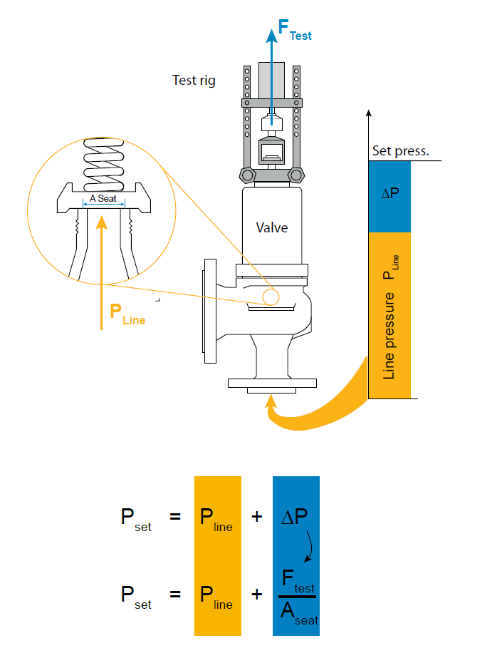
The EVT-Pro device simultaneously examines two critical variables of the relief device — the upward force applied to the spindle and the actual system pressure. Using sophisticated sensors, including an acoustic device, EVT-Pro testing accurately determines the pressure relief valve’s set pressure. It can also immediately sense and automatically close a relief device should it remain open during a test – a unique safety feature built into the software and hardware.

Safety is of the utmost importance when dealing with pressure relief valves. The valve is designed to limit system pressure, and it is critical that they remain in working order to prevent an explosion. Explosions have caused far too much damage in companies over the years, and though pressurized tanks and vessels are equipped with pressure relief vales to enhance safety, they can fail and result in disaster.
That’s also why knowing the correct way to test the valves is important. Ongoing maintenance and periodic testing of pressurized tanks and vessels and their pressure relief valves keeps them in working order and keep employees and their work environments safe. Pressure relief valves must be in good condition in order to automatically lower tank and vessel pressure; working valves open slowly when the pressure gets high enough to exceed the pressure threshold and then closes slowly until the unit reaches the low, safe threshold. To ensure the pressure relief valve is in good working condition, employees must follow best practices for testing them including:
If you consider testing pressure relief valves a maintenance task, you’ll be more likely to carry out regular testing and ensure the safety of your organization and the longevity of your
It’s important to note, however, that the American Society of Mechanical Engineers (ASME) and National Board Inspection Code (NBIC), as well as state and local jurisdictions, may set requirements for testing frequency. Companies are responsible for checking with these organizations to become familiar with the testing requirements. Consider the following NBIC recommendations on the frequency for testing relief valves:
High-pressure steam boilers 400 psi and greater – pressure test to verify nameplate set pressure every three years or as determined by operating experience as verified by testing history
High-temperature hot water boilers (greater than 160 psi and/or 250 degrees Fahrenheit) – pressure test annually to verify nameplate set pressure. For safety reasons, removal and testing on a test bench is recommended
When testing the pressure relief valve, raise and lower the test lever several times. The lever will come away from the brass stem and allow hot water to come out of the end of the drainpipe. The water should flow through the pipe, and then you should turn down the pressure to stop the leak, replace the lever, and then increase the pressure.
One of the most common problems you can address with regular testing is the buildup of mineral salt, rust, and corrosion. When buildup occurs, the valve will become non-operational; the result can be an explosion. Regular testing helps you discover these issues sooner so you can combat them and keep your boiler and valve functioning properly. If no water flows through the pipe, or if there is a trickle instead of a rush of water, look for debris that is preventing the valve from seating properly. You may be able to operate the test lever a few times to correct the issue. You will need to replace the valve if this test fails.
When testing relief valves, keep in mind that they have two basic functions. First, they will pop off when the pressure exceeds its safety threshold. The valve will pop off and open to exhaust the excess pressure until the tank’s pressure decreases to reach the set minimum pressure. After this blowdown process occurs, the valve should reset and automatically close. One important testing safety measure is to use a pressure indicator with a full-scale range higher than the pop-off pressure.
Thus, you need to be aware of the pop-off pressure point of whatever tank or vessel you test. You always should remain within the pressure limits of the test stand and ensure the test stand is assembled properly and proof pressure tested. Then, take steps to ensure the escaping pressure from the valve is directed away from the operator and that everyone involved in the test uses safety shields and wears safety eye protection.
After discharge – Because pressure relief valves are designed to open automatically to relieve pressure in your system and then close, they may be able to open and close multiple times during normal operation and testing. However, when a valve opens, debris may get into the valve seat and prevent the valve from closing properly. After discharge, check the valve for leakage. If the leakage exceeds the original settings, you need to repair the valve.
According to local jurisdictional requirements – Regulations are in place for various locations and industries that stipulate how long valves may operate before needing to be repair or replaced. State inspectors may require valves to be disassembled, inspected, repaired, and tested every five years, for instance. If you have smaller valves and applications, you can test the valve by lifting the test lever. However, you should do this approximately once a year. It’s important to note that ASME UG136A Section 3 requires valves to have a minimum of 75% operating pressure versus the set pressure of the valve for hand lifting to be performed for these types of tests.
Depending on their service and application– The service and application of a valve affect its lifespan. Valves used for clean service like steam typically last at least 20 years if they are not operated too close to the set point and are part of a preventive maintenance program. Conversely, valves used for services such as acid service, those that are operated too close to the set point, and those exposed to dirt or debris need to be replaced more often.
Pressure relief valves serve a critical role in protecting organizations and employees from explosions. Knowing how and when to test and repair or replace them is essential.

The Electronic Valve Tester, (EVT), is a digital computerized, hydraulic assisted device, designed to test and set safety/relief valves while in service. The EVT is portable and can be used under normal operating conditions without over pressuring the system.
Our Factory and National Board certified technicians, provide total safety/relief valve evaluation utilizing EVT technologies... at your convenience. The Electronic Valve Tester has been approved by the ASME for set point evaluation and or adjustment.
EVT service eliminates the need to overpressure the system for testing. Under normal operating conditions, we save test medium and unnecessary stress on the overall system.
The new platform of CALDER advanced valve testing systems manufactured by CLIMAX are the safest, most accurate and most versatile systems on the market, and we are pleased to announce our new line-up of valve testing equipment.
The HYDROPRO™ Console is the most versatile and user-friendly tester in the industry, capable of performing a wide variety of valve tests when paired with a CALDER hydraulic clamping system or even blind flanging. Every component in the tester is OEM-certified to the maximum pressure of the system, CE certified, and manufactured under full ISO certification – no one else in the industry can say the same! This means vastly superior quality, safety, durability and performance for you, our customer. Our testers are infinitely configurable to meet your exact needs, and our modular, common-platform design ensures that all equipment and accessories are plug-and-play compatible, so we can upgrade/expand your system in the field, anytime in the future, to meet your changing business needs. This is by far the most flexible and cost-effective way to manage your valve testing program and maximize your return on investment. HYDROPRO™ is available world-wide and backed by the vast CLIMAX global support network, not to mention the longest warranty in the industry. Not only is HYDROPRO™ more accurate than other comparable testers, it can perform multiple valve tests simultaneously to maximize your productivity. And that’s not all. . .
The HYDROPRO™ Universal Straight Valve Tester – Clamp Fixture clamps and seals straight-bodied valves for pressure testing. Capable of hydrostatic tests up to 9700 psi and low-pressure air tests up to 125 psi. Our unique tilting feature rotates clamped valves 90 degrees from horizontal to vertical, ensuring removal of all air prior to pressurizing the system. Our patented Easy-Out Seal Plate Holders allow quick change-out of seal plates from flanged to other valve end type connections without the use of special tools, bolts, nuts or gaskets.
The HYDROPRO™ Universal Flange Valve Tester – Clamp Fixture clamps and seals flanged valves for pressure testing. Capable of hydrostatic tests up to 9700 psi and low-pressure air tests up to 125 psi. Our unique tilting feature rotates clamped valves 90 degrees from horizontal to vertical, ensuring removal of all air prior to pressurizing the system. Paired with a HYDROPRO™ Hydraulic Flange Seal (below) this is the best way to test API valves, where cross body pressure on the valve is not an option.
The HYDROPRO™ Hydraulic Flange Seal clamps and seals flanged valves for pressure testing and eliminates all those blind flanges. Paired with the HYDROPRO™ Universal Flange Valve Tester, it is capable of hydrostatic tests up to 9,700 psi and low pressure air tests up to 125 psi, enabling the user to test API valves that have multiple flanges as well as valves that aren’t straight, like elbow valves, 90’s and T’s.
The SAFETY RELIEF VALVE TESTER performs SRV set pressure and seat leakage tests. Our unique ‘J’ tube design allows for a free flow of air or water from the source to the SRV being tested providing a cushion of air under the SRV seat to prevent seat damage. The control panel is ergonomically designed 90 degrees from the clamp fixture to provide splash shield partition between the operator and the clamp table.
The CALDER TURN-AROUND-TESTER™, is designed for easy transportation to jobsites making it ideal for valve servicing companies or plant turn-arounds, eliminating the need for taking valves back to the shop. This flanged valve testing system conforms to specified API-598 and allows the operator to perform hydrostatic valve testing in non-traditional environments. Complete with clamp fixture and control console, the TURN-AROUND-TESTER™ is a one-stop shop for valve testing on-site.
The SMARTEST™ – DAAS captures the performance of your valve test digitally. The system will allow the operator to isolate any point along the graph line of the test to display the numeric value of the pressure. Data can be reported in both .PDF and .CSV file formats. Built-in Wi Fi capability allows for easy and secure sharing of data. This rugged splash-proof (IP67) unit is ideal for industrial valve testing environments.
The SMARTEST PLUS ™ – DACS gives the user maximum control of the valve test allowing for increased and unrivaled productivity. It enables programmable, automated, hands-free control of the test procedure.The Variable Sample Rate provides a high density data stream which is suitable for most short term tests. With the ability to capture 10 samples per second, that’s over 216,000 data points in a 1 hour test. The SMARTEST PLUS ™ DACS system is upgradeable for multiple input channels giving the user more access to pressure or temperature data. Wi Fi enabled, the system allows the user to send results directly to any email address, while storing results on the DACS hard drive.
Lightweight for easy handling and installation, our valve grinding and lapping machines span working ranges for gate valves from 1.3 to 39.4 inches (32 to 1000 mm). You can quickly change grinding disks and adjust the grind pressure during operation. We also have many specialty and custom products for valve repair applications. Give us a call, there’s no job we can’t do!

vpl has put you on the right track. The Trevitest Device is one brand of Lift Assist Device (others include KISS, EVT, PVT AVK, Hydroset, SPIVOT). SOme are manufactured by Pressure Relief Valve Companies, others by Valve Repair Shops and some are third party vendors with PRV background. A Pressure Relief Valve typically uses a spring (Force S) to hold a movable sealing member (disc) closed on a fixed sealing member (nozzle) until the system pressure (Force P) overcomes the Spring and opens the PRV to relieve an overpressure situation. The PRV works on the simple principle that IF Force S > Force P THEN the PRV remains closed (Static Force Balance Principle). However, IF Force P > Force S THEN the PRV is Open.
The problem is that most Steam Power Generating Stations, whether Fossil or Nuclear, are such high pressure and under so much demand for electricity that they do want to take the time or liability to overpressure their boilers to test Safety Valve Set Pressure. Use of the Lift Assist Device is permitted by ASME Code (both Sec. I, Power Boilers, & Sec. VIII, Pressure Vessels) to determine the Set Pressure of a PRV (Safety, Safety-Relief or Relief Valve).
The Equipment Required is a Calibrated System Pressure Gauge, a Lift Assist Device with an adapter to connect to the PRV Stem, a Calibrated Load Cell to measure the Force Applied to the PRV Stem, a calculator or PC with a program to determine the Set Pressure from the input data and most importantly, a Valve Technician who knows PRV Terminology, and is familiar with the Test Equipment.

This second edition of Fire Apparatus Driver/Operator has been thoroughly updated to serve as a complete training solution that addresses pump operation, safe driving techniques, tiller and aerial apparatus operation, and water supply considerations. From basic apparatus maintenance to fire pump theory and advanced hydraulic calculations, this single manual covers everything a fire service driver/operator needs to know. Fire Apparatus Driver/Operator: Pump, Aerial, Tiller, and Mobile Water Supply, Second Edition meets and exceeds the job performance requirements of Chapters 4, 5, 6, 7, and 10 of NFPA 1002, Fire Apparatus Driver/Operator Professional Qualifications, 2014 Edition. The second edition features: - An emphasis on Driver/Operator safety and responsibility with a dedicated chapter on safety. - Actual Near-Miss Reporting System cases are discussed to drive home important points about safety and the lessons learned from these real-life incidents. - Detailed step-by-step skill drills which include the corresponding NFPA job performance requirement. - Scenario based learning tools including You are the Driver/Operator, Driver/Operator in Action, and Voices of Experience case studies to encourage critical thinking skills - Driver/Operator Tips and Safety Tips to provide helpful advice from fireground veterans.


 8613371530291