
firematic safety valve factory

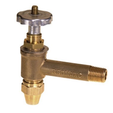
In our oil safety valve photo at page top the OSV is in the OPEN position - the telltale indicator is that the screw is visible protruding up through the top of the silver-gray valve handle.
Fusible-link oil line valves such as the Fire-o-Matic valve work opposite from usual plumbing valves - that is, internally, because of the "reverse-threaded" valve stem, these oil line control and safety valves seem to operate backwards from what you"d expect.
To Open the OSV - let oil flow: turn the oil line valve counter-clockwise (left to right - in the direction of my finger to OPEN heating oil fuel flow. The threadsOn this part are cut opposite from usual plumbing shutoff valves. As you turn the valve handwheel in this direction the threaded valve stem will protrude upwards through the rotating knob. Oil will flow when the valve is open. In my photo the valve was about half-way open.
When the valve stem protrudes fully up through the turn-knob as far as possible you have compressed an internal spring inside the valve, and the valve is open to let oil flow. The handwheel actually feels "tighter" (as you are compressing the spring) and the handwheel moves down against the valve body as the valve opens.
To Close the OSV - stop oil flow: rn the Firematic type OSV clockwise (right to left) to close the valve and stop oil flow. As you turn the valve handwheel or knob in this direction (opposite to the direction my finger is pointing) the valve stem will disappear down into the valve body, pushed by its internal spring. You are closing the valve - oil will not flow.
When the turn knob is rotated so that the valve stem moves down through the knob until the stem end is flush with the knob top and the knob is loose, the valve is fully closed and oil will not flow.
Watch out: if the control valve on a heating oil line is not a fusible-link safety valve such as the Fire-o-Matic™, it will probably be an ordinary plumbing stop valve that works as all plumbing valves:clockwise closes those valves by moving the valve stem down and counter-clockwise to move the valvestem up opens them. Sometimes we find a common stop valve on the oil line at the oil tank and a fusible-link safety valve just at each oil burner.
An internal spring pressure, combined with a fusible link in the valve stem are what shut the oil line valve in event of a fire. In this design, when the valve is open to permit heating oil to flow it is also under spring tension. Because the valve includes a fusible link, in event of a fire the fusible link melts and the internal spring pushes the valve stem down, closing the valve and stopping oil flow.
As you turn the handle on the oil piping safety valve counter-clockwise you will feel increasing spring tension as you are opening the valve (lifting the stem out of the valve body) against the spring pressure.
Because of the use of "reverse" threads on the valve stem, when you turn the OSV knob counter-clockwise the underside of the control knob, remaining in contact with the surface of the valve body, causes the valve stem to move up (against pressure of the valve"s internal spring) until the threaded stem protrudes fully through the knob and you cannot turn the knob any more. In my photo the valve is about half-way open.
When the valve is fully open to permit fuel flow, the valve stem is "all the way out" of the valve body and the valve is being pushed-on by the internal spring. In this position the valve"s knob has been turned clockwise, all the way down against the body of the valve.
When this oil line fusible-link valve is completely open to heating oil fuel flow, the valve stem is screwed all the way up "out" of the valve body. As you turn the valve knob clockwise you"ll feel it moving against the internal valve spring pressure and you will see the valve stem moving up and out through the center of the oil valve knob.
When the oil safety valve handle is screwed clockwise (right to left) so that the threaded rod has disappeared fully down into the valve body the valve handle will become loose and the valve internal components will be in the closed position - heating oil fuel will not flow.
Because of the use of "reverse threads" on the valve stem, when you turn the OSV knob clockwise , as the knob itself remains in contact with the valve body, the spring-loaded valve stem will move down into the valve body, closing off the oil flow.
As you turn the oil valve knob clockwise you will see the valve stem move back into the valve body and you will feel the spring tension on the device lessen.
For the last few counter-clockwise turns on the valve stem/screw you should feel a complete release of tension of the spring mentioned just above and if you keep turning the valve knob counter-clockwise it will unscrew and come off. Don"t panic if this happens. The threaded portion of the valve stem protrudes up through the valve body and you can simply screw the knob back on.
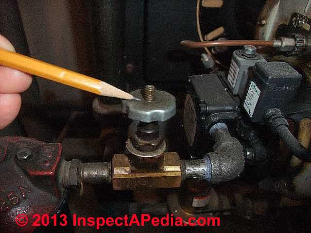
In our OSV photos below, the first photo (below left) shows the oil line safety valve in the OPEN positin - oil will flow when the threaded portion of the valve shaft extends fully up through the rotatable knob pointed to by my pencil.
In our heating oil line valve photo at above right the valve has been manually CLOSED - no oil will flow. The threaded valve stem has disappeared down into the valve body and has shut off the valve and oil flow.
Watch out: if (for example in case of a fire) the fusible link inside of an OSV has melted permitting the spring to close the valve, then from outside the valve may look as if it is in the open position - the threaded stem will still be poking out - but the valve has snapped and closed internally.
Put another way: if you turn the oil line valve until the handle begins to come off, the valve is in the CLOSED position. You will see that at this point you have removed all tension against the valve"s internal spring and the spring has pushed the valve shut or closed. The valve stem has moved into the valve body.
If you turn the valve against its spring tension the valve is in its OPEN position. You will see that in this position you have turned the valve against its spring tension - the spring tension is increased - and the valve is open. The valve stem has moved out of the valve body.
at OIL FILTERS on HEATING EQUIPMENT where during heating equipment oil filter servicing the valve is used to close and later open the oil line feeding the oil burner
Thanks so much; what a great way to remember which way to turn the fire-o-matic valve stem: NO STEM = NO OIL - if you don"t see the valve stem poking up through the knob then the valve has been closed.
This is such a helpful article ! Thank you . After reading it I"ve concluded - " no stem , no oil " so I just remember that as I gently turn the valve handle ;
Thanks! I kind of freaked out a bit after changing the filter wondering why when i opened the valve no oil was coming through. I thought I just turned my dollar saving filter changing exercise into an expensive service call....
Sorry forgot to add yes I have turned the valve completely counterclockwise all the way to the point it does move anymore and the stem is fully exposed. I"ve also turned the furnace on and bled the burner so it appears that there is absolutely oil going thru the lines when the furnace is calling.
I believe it is tank->supply line-> OSV -> in to filter -> out to the burner, then another line that appears to go out (which seems to me to be a 2 line?), no other valves in that setup that I saw.
My valve looks the same as this but when it is in the Open position it doesn"t seem that oil flows through on it"s own, but when I turn the boiler on and there is a call for oil it is definitely going through. I discovered this as I went to change the filter and wanted to open the valve to release any air that may have been in the line, but with the valve open no oil was flowing, only when the boiler is on and calls. Is there something special about how this has been setup that it would do this?
So....left to right is CLOCKWISE,,,,,right to left is COUNTERCLOCKWISE.....to CLOSE the valve you rotate counterclockwise and allow the inner spring to close the valve. To OPEN the valve you would rotate clockwise and provide a counterbalance to the spring.
Sometimes a valve is loosened so as to allow the valve spring to close the valve but the valve sticks. A technician might tap gently on the valve stem to be sure it"s fully CLOSED.
These oil valve turned in the opposite direction from that to which you are accustomed. It sounds as though you were turning off the oil flow to your burner. That"s why the burner goes off.
Counter-clockwise turning of the handwheel on an OSV feels as if you are "tightening" the valve and the valve stem moves "up" through the handwheel - fully CCW opens the valve and oil can flow. The valve stem is "reverse threaded" compared with normal plumbing valves.
I think you"ve got your open and closed backwards, you seem to say the same thing for both normal valves and firematic valves ( See under watch out Clock wise is open ccw is closed ?) Confusing. While under summary, you have it correct.
Watch out: if you break it off you"ll have a financially ruinous oil tank flood in your home so take great care. If some fool does snap off an oil valve and can"t otherwise shut off oil flowing from an above ground oil tank, for an emergency repair just bent and crimp the copper tubing to stop the oil flow.
You describe an irritating problem indeed. If the oil safety valve simply won"t close you"re at least lucky to continue to have heat. The solution is to use up oil in the tank, have its remains pumped out, then replace the valve.
- the line is cut near the oil tank (or near the oil burner where an OSV valve should be anyway) and a second new working valve is installed on the lines.
I suppose a very confident plumber with help from an assistant might try putting down a pan, trying to fix the valve while spilling oil, but given the trouble of cleaning up an oil spill that live approach makes me nervous.
Question: I have a fire-O-matic valve attached directly to the oil tank: it"s now open and the furnace is running fine. I would like to close the valve and replace the downstream filter element. But when I turn the handle in either direction the stem turns with the handle..
.in other words, I cannot close the valve. I"ve tried the tapping on the end of the stem approach mentioned in the stuck valve section, but to no avail.
"When the valve is fully open to permit fuel flow, the valve stem is "all the way out" of the valve body and the valve is being pushed-on by the internal spring. In this position the valve"s knob has been turned clockwise, all the way down against the body of the valve.
When this oil line fusible-link valve is completely open to heating oil fuel flow, the valve stem is screwed all the way up "out" of the valve body. As you turn the valve knob clockwise you"ll feel it moving against the internal valve spring pressure and you will see the valve stem moving up and out through the center of the oil valve knob."
In both of these paragraphs the use of the word clockwise should be replaced with the word Counter-clockwise. I know this is just a typo but it will be very confusing to someone who is not familiar with these valves. It"s hard enough for people to understand without adding typos to the mix. Other than this thank you for publishing an excellent article.
If you have a fusible link valve that doesn"t seem to turn off you might try tapping the exposed end of the valve stem. I have found a stuck, or slow to close OSV on a few rare occasions. A gentle tap, not hard enough to damage threads, loosens it after which I open and close the valve a few times to convince myself it now moves freely. A burr on the brass interior or more likely internal sludge or debris could be the culprit.
Because at the oil burner the OSV is likely to be used at least once a year during service, that"s a good opportunity to discover if the valve is not closing fully.
What is the difference among all these different kinds of valves used on oil piping and at the oil burner or oil tank: check valve, fusible link valve, fire-o-matic type valve, vacuum operated valves, quickstop valves, solenoid valves, and oil delay valves. It"s really confusing.
We agree that there are enough valves and enough similarity in their names that the controls used at oil tanks, on oil piping, and at the oil burner to manage the flow of oil can be confusing. Worse, valves that do different things and have different purposes may all be called "oil safety valves" in marketing and technical literature.
Don"t confuse the built-in check valve in the fuel unit with external check valves, fusible link oil safety valves, solenoid operated quick-stop oil valves, and their sisters, solenoid operated oil delay valves.
OIL LINE SAFETY VALVE TURN DIRECTION to OPEN or SHUT at InspectApedia.com - online encyclopedia of building & environmental inspection, testing, diagnosis, repair, & problem prevention advice.
[10] Firomatic Globe Type Oil Line Valves & Lever Type Fusible Link Control Valves:ISP Automation, Inc., 1035 Old Georges Road, North Brunswick, NJ 08902, Phone: 866-383-3481, FAX 866-383-3482, Email: support@ispautomation.com
[14] "The Oil Safety Valve (Service)", Charles Bursey, Sr., Fuel Oil News, February 2006 (Still trying to get the full article - October 2008 - DF) Charles W. Bursey Sr. can be reached at F.W. Webb Co. www.fwwebb.com/
[19] Thanks to reader Bernie Daraz for suggesting the need for clear photographs illustrating the OSV or oil line safety valve in the open and closed positions. Personal correspondence 2/15/2013.
Thanks to Rick Johnston for pointing out that the more likely cause of a fire safety valve in the return oil line is a burst seal on the fuel unit 4/6/2009
Thanks to reader T.R. for suggesting clarity on where oil safety valves should or should not be installed and for discussing the proper hook-up location for the Tigerloop and similar oil line prime protection & air removal devices. April 2011.
![]()
Fusible Fire Safety Valves are designed to reduce fire damage by shutting off the flow of oil from the oil tank in the event of a fire. They are required by code in residential oil heating installations in conformance with NFPA 31.All valves are embossed with an arrow indicating the direction of oil flow
R.W. Beckett’s burner controls were created with customer satisfaction and safety in mind. Our entire suite of burner controls utilizes the most current technology to safely control the combustion process.
Recently, we became aware of a design deficiency in our ½” ‘Firomatic’ Fusible Safety Valve part number 12130. This bulletin covers ONLY the ½” FPT version p/n 12130, previous p/n B200F.
Under certain conditions, if the valve is exposed to temperatures exceeding the handle’s temperature rating and the valve ‘fires’ or actuates, the stem may not travel far enough to properly seat the valve and shut off the flow of fuel. This could result in a dangerous situation if there is a ruptured fuel line downstream of the valve. There have been no reports of this situation arising, but the potential for this issue to occur does exist. This does not affect the valve’s operation when used as a manual shut off valve.
The current design of the 12130 – ½” FPT valve and handle assembly was in production prior to R W Beckett’s acquisition of the Firomatic® product line. We have been unable to determine exact dates for any changes made to the design by previous manufacturers. Therefore this bulletin covers all Firomatic® ½” FPT valves, whether using our part number 12130 or the obsolete part number B200F, used by Highfield Manufacturing. Suspect valves can be identified by the name ‘Firomatic’ cast into the body of the valve. See illustration below.
A re-design of the 12130 valve will be available pending agency approvals and manufacturing process lead times. We are anticipating the re-designed valve to be available by January 1, 2017.
Please immediately begin identifying suspect valves in service for retrofit. Retrofit kit part number 12130VR will be available from any Beckett Distributor or by contacting our Customer Service Department. A $50.00 Labor Allowance will be paid for each valve retrofitted. Instructions for adding the kit to installed valves are included with the kit. Estimated completion time to perform retrofit is less than 10 minutes.
To retrofit an existing valve, approximately 3½” of clearance above the top of the valve stem will be required. If there is not enough clearance to proceed with the retrofit, the valve will have to be replaced or an additional valve will need to be installed downstream. Availability of replacement valves is pending (see above). Along with credit for the valve, a $125.00 Labor Allowance will be paid for each valve replaced.
Only ‘Firomatic’ versions of this valve are affected. A picture of the affected valve is shown above. ONLY those valves with the name cast into the valve body need attention.
Did you know that Globe"s Universal Manifold Check (UMC) provides an Adjustable Relief Valve factory set at 175psi and field adjustable to 310psi? Cost Savings = Gives engineers many upfront design options while also eliminating the need for the installing contractor to remove the traditional fixed relief valve for mandatory 200psi hydrostatic tests; save time and money.


 8613371530291