
full bore safety valve working principle in stock

(WIRE DRAWING– IT IS THE CONDITION IN WHICH A THIN FILM OF STEAM BLOWS ACROSS BETWEEN THE VALVE FACES CAUSING THE CUTTING OF THE VALVE FACES WHICH LEADS TO THE LOSS OF THE VALVE STEAM.)
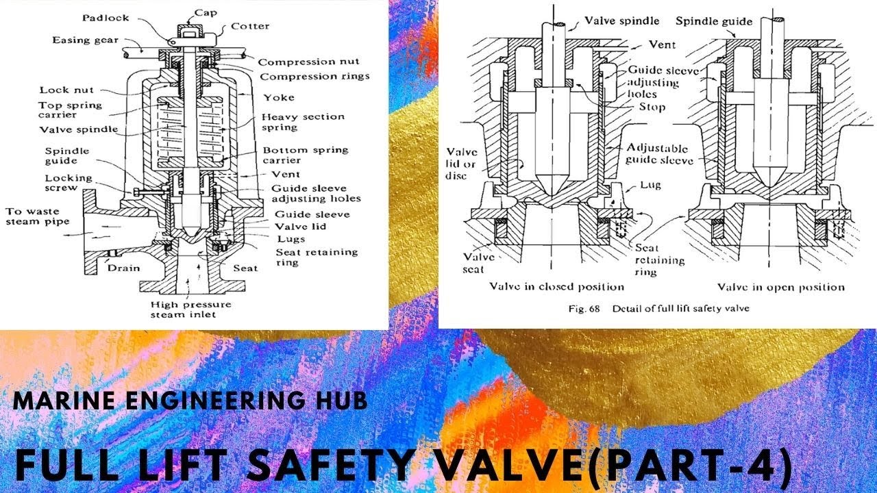
3.WHEN THE STEAM ACTS ON THE OPERATING PISTON IT CAUSES THE OPENING OF THE MAIN VALVE AGAINST THE SPRING PRESSURE. AS THE DIAMETER IS TWICE OF THE MAIN VALVE IT CAUSE THE D/4 LIFTING OF THE MAIN VALVE(i:e- FULL LIFT OF THE SAFETY VALVE).
There is a wide range of safety valves available to meet the many different applications and performance criteria demanded by different industries. Furthermore, national standards define many varying types of safety valve.
The ASME standard I and ASME standard VIII for boiler and pressure vessel applications and the ASME/ANSI PTC 25.3 standard for safety valves and relief valves provide the following definition. These standards set performance characteristics as well as defining the different types of safety valves that are used:
ASME I valve - A safety relief valve conforming to the requirements of Section I of the ASME pressure vessel code for boiler applications which will open within 3% overpressure and close within 4%. It will usually feature two blowdown rings, and is identified by a National Board ‘V’ stamp.
ASME VIII valve- A safety relief valve conforming to the requirements of Section VIII of the ASME pressure vessel code for pressure vessel applications which will open within 10% overpressure and close within 7%. Identified by a National Board ‘UV’ stamp.
Full bore safety valve - A safety valve having no protrusions in the bore, and wherein the valve lifts to an extent sufficient for the minimum area at any section, at or below the seat, to become the controlling orifice.
Conventional safety relief valve -The spring housing is vented to the discharge side, hence operational characteristics are directly affected by changes in the backpressure to the valve.
Balanced safety relief valve -A balanced valve incorporates a means of minimising the effect of backpressure on the operational characteristics of the valve.
Pilot operated pressure relief valve -The major relieving device is combined with, and is controlled by, a self-actuated auxiliary pressure relief device.
Power-actuated safety relief valve - A pressure relief valve in which the major pressure relieving device is combined with, and controlled by, a device requiring an external source of energy.
Standard safety valve - A valve which, following opening, reaches the degree of lift necessary for the mass flowrate to be discharged within a pressure rise of not more than 10%. (The valve is characterised by a pop type action and is sometimes known as high lift).
Full lift (Vollhub) safety valve -A safety valve which, after commencement of lift, opens rapidly within a 5% pressure rise up to the full lift as limited by the design. The amount of lift up to the rapid opening (proportional range) shall not be more than 20%.
Direct loaded safety valve -A safety valve in which the opening force underneath the valve disc is opposed by a closing force such as a spring or a weight.
Proportional safety valve - A safety valve which opens more or less steadily in relation to the increase in pressure. Sudden opening within a 10% lift range will not occur without pressure increase. Following opening within a pressure of not more than 10%, these safety valves achieve the lift necessary for the mass flow to be discharged.
Diaphragm safety valve -A direct loaded safety valve wherein linear moving and rotating elements and springs are protected against the effects of the fluid by a diaphragm
Bellows safety valve - A direct loaded safety valve wherein sliding and (partially or fully) rotating elements and springs are protected against the effects of the fluids by a bellows. The bellows may be of such a design that it compensates for influences of backpressure.
Controlled safety valve - Consists of a main valve and a control device. It also includes direct acting safety valves with supplementary loading in which, until the set pressure is reached, an additional force increases the closing force.
Safety valve - A safety valve which automatically, without the assistance of any energy other than that of the fluid concerned, discharges a quantity of the fluid so as to prevent a predetermined safe pressure being exceeded, and which is designed to re-close and prevent further flow of fluid after normal pressure conditions of service have been restored. Note; the valve can be characterised either by pop action (rapid opening) or by opening in proportion (not necessarily linear) to the increase in pressure over the set pressure.
Direct loaded safety valve -A safety valve in which the loading due to the fluid pressure underneath the valve disc is opposed only by a direct mechanical loading device such as a weight, lever and weight, or a spring.
Assisted safety valve -A safety valve which by means of a powered assistance mechanism, may additionally be lifted at a pressure lower than the set pressure and will, even in the event of a failure of the assistance mechanism, comply with all the requirements for safety valves given in the standard.
Supplementary loaded safety valve - A safety valve that has, until the pressure at the inlet to the safety valve reaches the set pressure, an additional force, which increases the sealing force.
Note; this additional force (supplementary load), which may be provided by means of an extraneous power source, is reliably released when the pressure at the inlet of the safety valve reaches the set pressure. The amount of supplementary loading is so arranged that if such supplementary loading is not released, the safety valve will attain its certified discharge capacity at a pressure not greater than 1.1 times the maximum allowable pressure of the equipment to be protected.
Pilot operated safety valve -A safety valve, the operation of which is initiated and controlled by the fluid discharged from a pilot valve, which is itself, a direct loaded safety valve subject to the requirement of the standard.
The common characteristic shared between the definitions of conventional safety valves in the different standards, is that their operational characteristics are affected by any backpressure in the discharge system. It is important to note that the total backpressure is generated from two components; superimposed backpressure and the built-up backpressure:
Subsequently, in a conventional safety valve, only the superimposed backpressure will affect the opening characteristic and set value, but the combined backpressure will alter the blowdown characteristic and re-seat value.
The ASME/ANSI standard makes the further classification that conventional valves have a spring housing that is vented to the discharge side of the valve. If the spring housing is vented to the atmosphere, any superimposed backpressure will still affect the operational characteristics. Thiscan be seen from Figure 9.2.1, which shows schematic diagrams of valves whose spring housings are vented to the discharge side of the valve and to the atmosphere.
By considering the forces acting on the disc (with area AD), it can be seen that the required opening force (equivalent to the product of inlet pressure (PV) and the nozzle area (AN)) is the sum of the spring force (FS) and the force due to the backpressure (PB) acting on the top and bottom of the disc. In the case of a spring housing vented to the discharge side of the valve (an ASME conventional safety relief valve, see Figure 9.2.1 (a)), the required opening force is:
In both cases, if a significant superimposed backpressure exists, its effects on the set pressure need to be considered when designing a safety valve system.
Once the valve starts to open, the effects of built-up backpressure also have to be taken into account. For a conventional safety valve with the spring housing vented to the discharge side of the valve, see Figure 9.2.1 (a), the effect of built-up backpressure can be determined by considering Equation 9.2.1 and by noting that once the valve starts to open, the inlet pressure is the sum of the set pressure, PS, and the overpressure, PO.
Balanced safety valves are those that incorporate a means of eliminating the effects of backpressure. There are two basic designs that can be used to achieve this:
Although there are several variations of the piston valve, they generally consist of a piston type disc whose movement is constrained by a vented guide. The area of the top face of the piston, AP, and the nozzle seat area, AN, are designed to be equal. This means that the effective area of both the top and bottom surfaces of the disc exposed to the backpressure are equal, and therefore any additional forces are balanced. In addition, the spring bonnet is vented such that the top face of the piston is subjected to atmospheric pressure, as shown in Figure 9.2.2.
The bellows arrangement prevents backpressure acting on the upper side of the disc within the area of the bellows. The disc area extending beyond the bellows and the opposing disc area are equal, and so the forces acting on the disc are balanced, and the backpressure has little effect on the valve opening pressure.
Bellows failure is an important concern when using a bellows balanced safety valve, as this may affect the set pressure and capacity of the valve. It is important, therefore, that there is some mechanism for detecting any uncharacteristic fluid flow through the bellows vents. In addition, some bellows balanced safety valves include an auxiliary piston that is used to overcome the effects of backpressure in the case of bellows failure. This type of safety valve is usually only used on critical applications in the oil and petrochemical industries.
Since balanced pressure relief valves are typically more expensive than their unbalanced counterparts, they are commonly only used where high pressure manifolds are unavoidable, or in critical applications where a very precise set pressure or blowdown is required.
This type of safety valve uses the flowing medium itself, through a pilot valve, to apply the closing force on the safety valve disc. The pilot valve is itself a small safety valve.
The diaphragm type is typically only available for low pressure applications and it produces a proportional type action, characteristic of relief valves used in liquid systems. They are therefore of little use in steam systems, consequently, they will not be considered in this text.
The piston type valve consists of a main valve, which uses a piston shaped closing device (or obturator), and an external pilot valve. Figure 9.2.4 shows a diagram of a typical piston type, pilot operated safety valve.
The piston and seating arrangement incorporated in the main valve is designed so that the bottom area of the piston, exposed to the inlet fluid, is less than the area of the top of the piston. As both ends of the piston are exposed to the fluid at the same pressure, this means that under normal system operating conditions, the closing force, resulting from the larger top area, is greater than the inlet force. The resultant downward force therefore holds the piston firmly on its seat.
If the inlet pressure were to rise, the net closing force on the piston also increases, ensuring that a tight shut-off is continually maintained. However, when the inlet pressure reaches the set pressure, the pilot valve will pop open to release the fluid pressure above the piston. With much less fluid pressure acting on the upper surface of the piston, the inlet pressure generates a net upwards force and the piston will leave its seat. This causes the main valve to pop open, allowing the process fluid to be discharged.
When the inlet pressure has been sufficiently reduced, the pilot valve will reclose, preventing the further release of fluid from the top of the piston, thereby re-establishing the net downward force, and causing the piston to reseat.
Pilot operated safety valves offer good overpressure and blowdown performance (a blowdown of 2% is attainable). For this reason, they are used where a narrow margin is required between the set pressure and the system operating pressure. Pilot operated valves are also available in much larger sizes, making them the preferred type of safety valve for larger capacities.
One of the main concerns with pilot operated safety valves is that the small bore, pilot connecting pipes are susceptible to blockage by foreign matter, or due to the collection of condensate in these pipes. This can lead to the failure of the valve, either in the open or closed position, depending on where the blockage occurs.
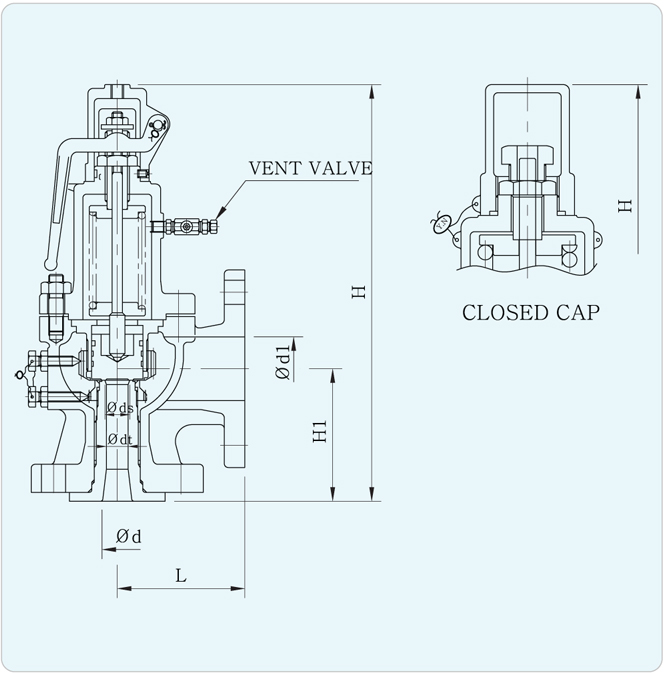
The terms full lift, high lift and low lift refer to the amount of travel the disc undergoes as it moves from its closed position to the position required to produce the certified discharge capacity, and how this affects the discharge capacity of the valve.
A full lift safety valve is one in which the disc lifts sufficiently, so that the curtain area no longer influences the discharge area. The discharge area, and therefore the capacity of the valve are subsequently determined by the bore area. This occurs when the disc lifts a distance of at least a quarter of the bore diameter. A full lift conventional safety valve is often the best choice for general steam applications.
The disc of a high lift safety valve lifts a distance of at least 1/12th of the bore diameter. This means that the curtain area, and ultimately the position of the disc, determines the discharge area. The discharge capacities of high lift valves tend to be significantly lower than those of full lift valves, and for a given discharge capacity, it is usually possible to select a full lift valve that has a nominal size several times smaller than a corresponding high lift valve, which usually incurs cost advantages.Furthermore, high lift valves tend to be used on compressible fluids where their action is more proportional.
In low lift valves, the disc only lifts a distance of 1/24th of the bore diameter. The discharge area is determined entirely by the position of the disc, and since the disc only lifts a small amount, the capacities tend to be much lower than those of full or high lift valves.
Except when safety valves are discharging, the only parts that are wetted by the process fluid are the inlet tract (nozzle) and the disc. Since safety valves operate infrequently under normal conditions, all other components can be manufactured from standard materials for most applications. There are however several exceptions, in which case, special materials have to be used, these include:
Cast steel -Commonly used on higher pressure valves (up to 40 bar g). Process type valves are usually made from a cast steel body with an austenitic full nozzle type construction.
For all safety valves, it is important that moving parts, particularly the spindle and guides are made from materials that will not easily degrade or corrode. As seats and discs are constantly in contact with the process fluid, they must be able to resist the effects of erosion and corrosion.
The spring is a critical element of the safety valve and must provide reliable performance within the required parameters. Standard safety valves will typically use carbon steel for moderate temperatures. Tungsten steel is used for higher temperature, non-corrosive applications, and stainless steel is used for corrosive or clean steam duty. For sour gas and high temperature applications, often special materials such as monel, hastelloy and ‘inconel’ are used.
Standard safety valves are generally fitted with an easing lever, which enables the valve to be lifted manually in order to ensure that it is operational at pressures in excess of 75% of set pressure. This is usually done as part of routine safety checks, or during maintenance to prevent seizing. The fitting of a lever is usually a requirement of national standards and insurance companies for steam and hot water applications. For example, the ASME Boiler and Pressure Vessel Code states that pressure relief valves must be fitted with a lever if they are to be used on air, water over 60°C, and steam.
A test gag (Figure 9.2.7) may be used to prevent the valve from opening at the set pressure during hydraulic testing when commissioning a system. Once tested, the gag screw is removed and replaced with a short blanking plug before the valve is placed in service.
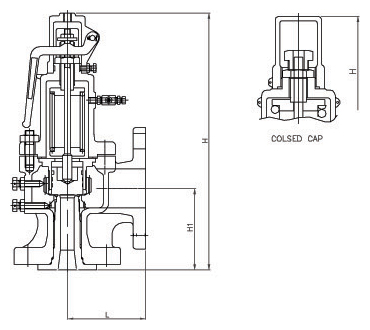
The amount of fluid depends on the particular design of safety valve. If emission of this fluid into the atmosphere is acceptable, the spring housing may be vented to the atmosphere – an open bonnet. This is usually advantageous when the safety valve is used on high temperature fluids or for boiler applications as, otherwise, high temperatures can relax the spring, altering the set pressure of the valve. However, using an open bonnet exposes the valve spring and internals to environmental conditions, which can lead to damage and corrosion of the spring.
When the fluid must be completely contained by the safety valve (and the discharge system), it is necessary to use a closed bonnet, which is not vented to the atmosphere. This type of spring enclosure is almost universally used for small screwed valves and, it is becoming increasingly common on many valve ranges since, particularly on steam, discharge of the fluid could be hazardous to personnel.
Some safety valves, most commonly those used for water applications, incorporate a flexible diaphragm or bellows to isolate the safety valve spring and upper chamber from the process fluid, (see Figure 9.2.9).
As soon as mankind was able to boil water to create steam, the necessity of the safety device became evident. As long as 2000 years ago, the Chinese were using cauldrons with hinged lids to allow (relatively) safer production of steam. At the beginning of the 14th century, chemists used conical plugs and later, compressed springs to act as safety devices on pressurised vessels.
Early in the 19th century, boiler explosions on ships and locomotives frequently resulted from faulty safety devices, which led to the development of the first safety relief valves.
In 1848, Charles Retchie invented the accumulation chamber, which increases the compression surface within the safety valve allowing it to open rapidly within a narrow overpressure margin.
Today, most steam users are compelled by local health and safety regulations to ensure that their plant and processes incorporate safety devices and precautions, which ensure that dangerous conditions are prevented.
The principle type of device used to prevent overpressure in plant is the safety or safety relief valve. The safety valve operates by releasing a volume of fluid from within the plant when a predetermined maximum pressure is reached, thereby reducing the excess pressure in a safe manner. As the safety valve may be the only remaining device to prevent catastrophic failure under overpressure conditions, it is important that any such device is capable of operating at all times and under all possible conditions.
Safety valves should be installed wherever the maximum allowable working pressure (MAWP) of a system or pressure-containing vessel is likely to be exceeded. In steam systems, safety valves are typically used for boiler overpressure protection and other applications such as downstream of pressure reducing controls. Although their primary role is for safety, safety valves are also used in process operations to prevent product damage due to excess pressure. Pressure excess can be generated in a number of different situations, including:
The terms ‘safety valve’ and ‘safety relief valve’ are generic terms to describe many varieties of pressure relief devices that are designed to prevent excessive internal fluid pressure build-up. A wide range of different valves is available for many different applications and performance criteria.
In most national standards, specific definitions are given for the terms associated with safety and safety relief valves. There are several notable differences between the terminology used in the USA and Europe. One of the most important differences is that a valve referred to as a ‘safety valve’ in Europe is referred to as a ‘safety relief valve’ or ‘pressure relief valve’ in the USA. In addition, the term ‘safety valve’ in the USA generally refers specifically to the full-lift type of safety valve used in Europe.
Pressure relief valve- A spring-loaded pressure relief valve which is designed to open to relieve excess pressure and to reclose and prevent the further flow of fluid after normal conditions have been restored. It is characterised by a rapid-opening ‘pop’ action or by opening in a manner generally proportional to the increase in pressure over the opening pressure. It may be used for either compressible or incompressible fluids, depending on design, adjustment, or application.
Safety valves are primarily used with compressible gases and in particular for steam and air services. However, they can also be used for process type applications where they may be needed to protect the plant or to prevent spoilage of the product being processed.
Relief valve - A pressure relief device actuated by inlet static pressure having a gradual lift generally proportional to the increase in pressure over opening pressure.
Relief valves are commonly used in liquid systems, especially for lower capacities and thermal expansion duty. They can also be used on pumped systems as pressure overspill devices.
Safety relief valve - A pressure relief valve characterised by rapid opening or pop action, or by opening in proportion to the increase in pressure over the opening pressure, depending on the application, and which may be used either for liquid or compressible fluid.
In general, the safety relief valve will perform as a safety valve when used in a compressible gas system, but it will open in proportion to the overpressure when used in liquid systems, as would a relief valve.
Safety valve- A valve which automatically, without the assistance of any energy other than that of the fluid concerned, discharges a quantity of the fluid so as to prevent a predetermined safe pressure being exceeded, and which is designed to re-close and prevent further flow of fluid after normal pressure conditions of service have been restored.

This is why pressure relief devices are known as the “last line of defense” for pressurized equipment. In large measure, accidents are caused when the pressure relief devices themselves fail to perform the function for which they are designed. Still, these essential devices are too-often ignored or not understood fully by the people in the industries they are designed to protect.
In the United States, use of such devices was spurred by the 1,700 boiler explosions that resulted in 1,300 deaths from 1905 to 1911. By 1915, the American Society of Mechanical Engineers (ASME) published its first boiler code, Rules for Construction of Stationary Boilers and Allowable Working Pressures, incorporating rules for construction and installation of safety valves for boilers.
The primary purpose of a pressure relief valve is to open to relieve excess pressure, reclose and prevent further flow of fluid after normal conditions have been restored (Figure 5). A secondary purpose is to minimize damage to other system components through operation of the pressure relief valve itself. A pressure relief valve designed under ASME Boiler and Pressure Vessel Code is stamped with the certification mark, and one of the certification designators: V, NV, HV, UV, UV3 or TV.
The many types of pressure relief valves that exist are based on different designs and construction. Generally, they’re classified as: safety relief valves, relief valves and safety valves.
A conventional safety relief valve is a spring-loaded pressure relief valve characterized by a rapid-opening pop action. Conventional safety relief valves are used for applications where excessive variable or built-up back pressure is not present in the system. The operational characteristics of these valves are directly affected by changes in the back pressure on the valve.
The working principle of a conventional spring-loaded safety relief valve is based on the balance of force. The spring load is preset to equal the force the inlet fluid exerts on the closed disk when the system pressure is at the set pressure of the valve.
The disk remains seated on the nozzle in the closed position when the inlet pressure is below the set pressure. The valve opens when the inlet pressure exceeds set pressure, overcoming the spring force. The valve recloses when the inlet pressure is reduced to a level below the set pressure.
Once the valve has opened, an additional pressure buildup at C occurs. This additional force at C causes the disk to lift substantially at pop. The valve closes when the inlet pressure has dropped sufficiently below the set pressure. The pressure at which the valve resets is called the closing pressure. The difference between the set pressure and closing pressure is the blowdown.
In the design of a conventional valve, an important consideration is seat leakage. This leakage can result in continuous loss of system fluid and may cause progressive damage to the valve seating surface. Based on the seating material, conventional valves are classified as:
Metal-seated valves. Metal-to-metal seats are commonly made from stainless or other hard alloy steels and are normally used for high-temperature applications such as steam and corrosive media applications for processing a wide variety of chemicals.
Soft-seated valve. An alternative to metal is resilient disks that can be fixed to either or both the seating surfaces where tighter shut-off is required. They are common for gas or liquid applications. These inserts may be made from a number of different materials, but Vinton, nitrile or EPDM (ethylene propylene diene monomer) are the most common.
Balanced bellows with auxiliary balancing piston. With this valve, the balanced bellows seal the body and fluid stream from the bonnet and working parts. The auxiliary balancing piston assures proper valve performance by compensating for back pressure in case the bellows fail.
The primary difference between a pilot-operated safety relief valve and a spring-loaded pressure relief valve is that the pilot-operated valve uses process pressure to keep the valve closed instead of a spring. A pilot is used to sense process pressure and to pressurize or vent the dome pressure chamber, which controls the valve opening or closing.
A pilot-operated safety relief valve consists of the main valve, a floating, unbalanced piston assembly, and an external pilot. The pilot controls the pressure on the top side of the main valve’s unbalanced moving chamber. A resilient seat is normally attached to the lower end.
At below-set level, the pressure on opposite sides of the moving member is equal. When the set pressure is reached, the pilot opens and depressurizes the cavity on the top side so the unbalanced member moves upward, causing the main valve to relieve. When the process pressure decreases to a predetermined pressure, the pilot closes, the cavity above the piston is depressurized and the main valve closes.
The valves operate bubble tight at higher operating pressure-to-set pressure ratios, allowing operators to run very close to the vessel’s maximum allowable working pressure.
Valve movement to open or close is fully controlled by a source of power such as electricity, steam or water (hydraulic). The valve may discharge to the atmosphere or to a container that is at lower pressure. The discharge capacity can be affected by downstream conditions.
Power-actuated safety relief valves are used mostly for forced-flow steam generators with no fixed steam or waterline. They are also used in nuclear power plants.
A temperature and pressure-actuated safety relief valve (also called a T&P safety relief valve) is a pressure relief valve that may be actuated by temperature or pressure on the inlet side (Figure 10).
Such a valve is designed for dual purposes. First, the T&P valve prevents temperature within a vessel from rising above a specified limit (generally 210°F or 98°C). Second, the T&P valve prevents pressure in the vessel from rising above a specified value.
A relief valve is actuated by inlet static pressure and a gradual lift that is generally proportional to the increase in pressure over opening pressure. Such a valve can be provided with enclosed spring housing suitable for closed discharge system applications.
Relief valves are commonly used in liquid systems, especially for lower capacities and thermal expansion applications. They also can be used on pump systems.
Adjustable relief valves feature convenient adjustment of the pressure setting through the outlet port. They are suitable for non-vented or vented inline applications in chemical, petrochemical and high-purity gas industries.
Electronic relief valves (ERVs) are pilot-operated relief valves that offer zero leakage. The ERV package combines a zero-leakage isolation valve with electric controls to monitor and regulate system pressure. These valves provide protection either in a capacity-relieving function or simply in an overpressure-protection application.
Safety valves are typically used for boiler overpressure protection and other applications such as downstream from pressure-reducing controls. These valves are installed wherever the maximum allowable working pressure of boilers is likely to be exceeded. Safety valves are also used for compressible gases, in particular for steam and air.
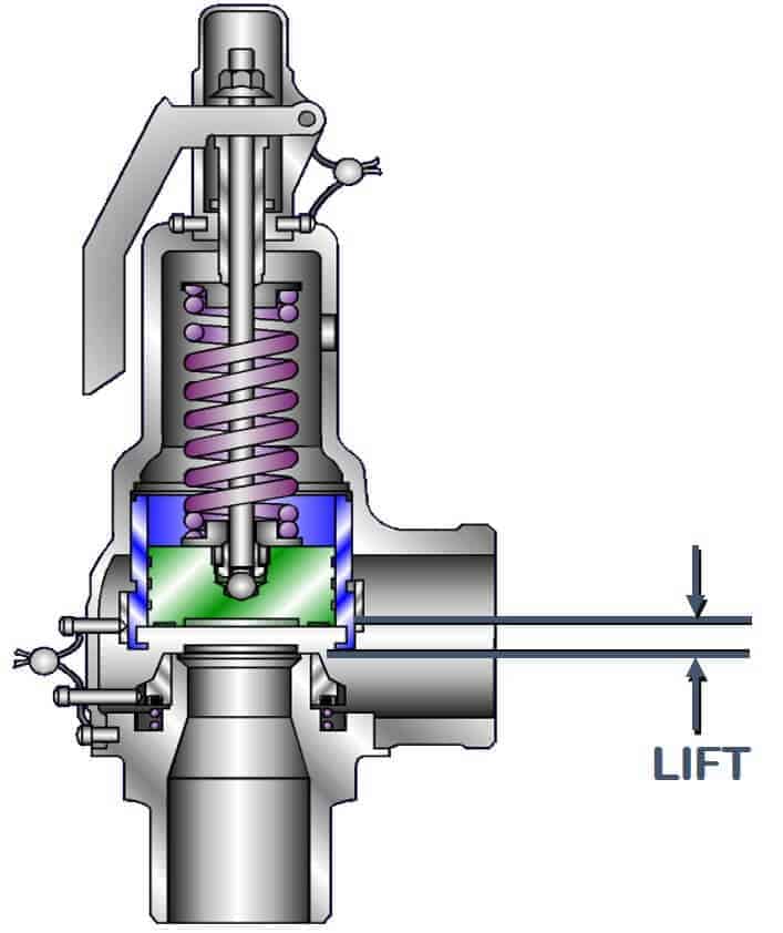
Safety valves are classified according to the lift. The term “lift” refers to the amount of travel the valve undergoes as it moves from its closed position to the position required to produce the certified discharge capacity.
Low-lift are safety valves in which the valve lifts a distance of 1/24th of the bore diameter. Since the valve has a small lift, the capacity is much lower than other types.
High-lift are safety valves in which the valve lifts a distance of at least 1/12th of the bore diameter. High-lift valves are used on compressible fluids, where their action is more proportional.
Full-lift are safety valves for which the valve lifts a distance of at least 1/4th of the bore diameter. Full-lift valves are considered the best choice for general steam applications.
Test gags are used to hold the safety valve closed while equipment is subjected to a hydrostatic test. To avoid damage to the spindle and/or seat, care is required so the gag screw is not tightened.
Lifting mechanisms are used to open the pressure relief valves when the pressure under the valve disk is lower than the set pressure. These mechanisms are available in three basic types: plain lever, packaged lever and air-operated lifting devices.
A key advantage of selecting a butterfly valve is the reduction of space and weight to a system compared with other options such as ball, check, globe or gate valves.

Safety valves are designed to automatically shut in the flow of a well in the event surface controls fail or surface equipment becomes damaged. They are classified according to the location from which they are controlled – surface or subsurface. In this article, subsurface safety valve types, operating systems, working principle, setting depth, and selection process are presented.
It is advisable, and in most cases mandatory, to have a secondary means of closure for all wells capable of natural flow to the surface. The installation on of a sub-surface safety valve (SSSV) will provide this emergency closure capability.
Operating systems may be either remotely operated on a fail-safe principle from surface (SCSSV) actuated from a control panel located on surface, or will be a subsurface controlled (SSCSV), designed to close automatically when a predetermined flow condition occurs in the well (actuated by the pressure differential/flow velocity across the valve).
In case of SCSSV, a 1/4″ inch stainless steel control line is attached to the outside of the tubing string and installed when the tubing is installed. Depending on the wellhead pressure, it may be necessary to keep as much as 4000 to 5000 psi on the control line to keep the valve open.
The differential type subsurface controlled subsurface safety valve senses pressure drop across a flow bean. There are several variations of the differential type SSCSV. Although they employ different sealing devices, such as a flapper or ball, they all are controlled with a flow bean and spring tension.
As shown in the following video, when hydraulic pressure is applied down a control line, the hydraulic pressure forces a sleeve within the valve to slide downwards. This movement compresses a large spring and pushes the flapper (in case of flapper type SCSSV) or the ball (in case of ball type SCSSV) downwards to open the valve. When hydraulic pressure is removed, the spring pushes the sleeve back up and causes the flapper (or the ball) to shut. In this way, it is failsafe and will isolate the wellbore in the event of a loss of the wellhead.
The location of the downhole safety valve within the completion is a precisely determined parameter intended to optimise safety. There are arguments against it either being too high or too low in the well and so the final depth is a compromise of all factors. MMS regulations state that the valve must be placed no less than 100′ below the mudline.

Pig kind of a ball or bullet with diameter of the pipe is used to clean pipes where clogging or other such problems occur. If that is the case then reduced bore will cause the PIG to get stuck in it and cant be used .
It is difficult to sometimes get confirmation whether Pig would be used or not etc. so as Basis to move ahead we could check what piping dept. is taking in that line for their manual On-Off valves .
One approach is for Utility Services like water etc we can save costs and go for reduced bore but for line where process fluid will be used full bore valves could be selected
Many a times it is in the Client design basis, Example – few clients I have worked with wanted Full bore regardless of the service. But this is ok if it is EPCM project but when it’s a LSTK project every decision counts in money.
In reduced bore pressure drop is a concern that must also be taken in consideration while selecting though the pressure drop is not high it could have an impact

Gate valves can have a rising or nonrising stem design. Rising stems are attached directly to the gate and provide a visual indicator of the valve position. Nonrising stems are generally threaded into the upper part of the gate and have a pointer threaded onto the top to indicate position. Nonrising stem designs are ideally suited for applications where vertical space is limited, in well applications, and where scraping or pigging is not required.
Gate valves are designed with a sealing unit to provide a tight seal around the stem. Our patented single loaded-spring (SLS) stem seal design, used in Saf-T-Seal slab gate valves and WKM Pow-R-Seal double expanding gate valves, provides superior leak protection and a self-adjusting seal designed to reduce maintenance.
Gate valves generally have one of four types of bonnets, which provide closure to prevent fluids from leaking out of the valve. Screw-in bonnets are simple, durable sealing units that use pressure to seal. Union bonnets provide easy access to the valve body for applications that may require frequent maintenance or inspection. Bolted bonnets are generally used for larger valves in higher-pressure applications. Pressure seal bonnets are designed for services with pressure in excess of 2,250 psi [15 MPa].
Because of the diversity of construction materials, trim offerings, and design combinations available with gate valves, they are appropriate for a wide variety of applications. From high-temperature coking units to food and pharmaceutical services, gate valves can be trusted to reliably perform.
The protected seat-face design of double expanding and slab gate valves eliminates degradation of the seat face caused by debris in the process fluid, which makes them ideal for liquid service. When additional protection is needed at points in pipeline applications where operational integrity is vital and the consequences of environmental exposure are higher, such as near waterways and municipalities, double expanding gate valves are a particularly wise choice.
Our smaller 2- to 4-in nonrising stem version of the Pow-R-Seal API 6A expanding gate valve is commonly used in wellhead manifold systems because of its reliable mechanical seal and high pressure capability.
Drilling manifold systems can also be easily designed to use certain gate valves, such as the Cameron DEMCO valve DM series, with space-saving and versatile mounting designs.
In the power industry, NEWCO gate, globe, and check valves and DOUGLAS CHERO forged-steel gate, globe, and check valves are ideal for standard and critical applications, such as steam distribution in power plants. By replacing the body and bonnet flanges with a welded connection, the design of this valve eliminates a leak path, reduces weight, and simplifies the application of exterior insulation. This, in concert with the forged steel body, provides the highest integrity sealing available.
For challenging subsea environments, where pressures are extremely high, temperatures are low, and operation is difficult, subsea manifolds that integrate valves and interface panels are used for critical isolation. The simple design of the Cameron RING-O subsea valve is ideally suited for integration into these systems and can be actuated manually, via ROV, or hydraulically for ease of operation.
There are lots of industrial valves in general industry, power plant, chemical plant, refining, oil and gas, water and wastewater treatment, with a variety of valve types, functions, size, materials, pressure rating, operation method, etc., It’s confusing for purchaser or Newbies who have just entered the valve industry.
So before introducing much terminology and technical knowledge, I shall picture a simple diagram to get a more intuitive understanding of all valves for you.
The ball valve is a type of isolation valve which is the most common valve used in industry, because of its excellent operating characteristics. The ball valve can be contacted by welding, threaded and flanged, and available in a wide range of sizes, materials, temperature, pressure, and tight shutoff.
Our headquarters STONE Valve in Taiwan has over 30 years of experience in manufacturing ball valves. Your project of the ball valve will take a professional quote and technical support.
Gate valve is the most common isolation valve in industry, with a linear motion to open and close the flow. As its disc is like a gate, so named a gate valve. There are various types of gate valves, knife gate valves, wedge gate valves, parallel slide gate valves, pipeline slab gate valves, and so on.
Gate valve only works for fully close and fully open, it can not be used for proportion controlling conditions. But as the passageway of a gate valve is unobstructed, which results in minimum pressure loss.
● Action time: Compare with the ball valve, the gate valve needs more time to open to close the valve. So it is usually used for application which doesn’t need frequent opening and closing, just simply to isolate the pipeline.
● Sealing: Ball valve has more excellent sealing performance than the gate valve. In the fully closed position and with flow pressure, the gate valve has a positive seal, but under very low pressure like 3psig, it maybe has a little leakage out of the gate valve seat.
Globe valve, here I talk about the conventional globe valve, not globe type control valve. I put a globe type control valve to the control valve part, which here means a stop valve.
A globe valve is often used for isolation service, the flow path through the globe valve follows a constantly changing process, which increased flow resistance, that’s why the globe valve has a higher pressure drop than the gate valve, plug valve, and ball valve(those valves are straight-through path)
According to the different body designs, the globe valve is classified as a Tee pattern globe valve, Z type globe valve, Y pattern globe valve, and angle pattern globe valve.
As a general rule, you can check the height of the screw stem between the handwheel and yoke, if only 1 – 3 thread displacement that means the globe valve is in a close position. When the valve is at an open position, it will show more height of the thread.
As a general rule, turn the handwheel clockwiseto close the globe valve, and turn counterclockwise to open the valve. There will be a switch mark and arrow on the handwheel.
The lifting check valve usually includes a piston check valve and ball check valve, it is particularly suitable for high-pressure conditions and special installation positions. The lifting check valve can be installed vertical pipeline or horizontal position.
The check valve also called the non-return valve which only allows water, air, steam, or other medium flow one-way direction. The main function of the check valve includes 4 points. To protect the pump or expensive equipment from reverse flow damage.
In a general rule, for the steam system here are 2 typical ways to use a check valve. If the outlet of the trap is recycled into the same condensate collection line, it needs to install a check valve, in case to prevent condensate water discharged from equipment in operation may flow back to other equipment that is not running.
There are many reasons to cause a water hammer in steam pipe systems. One of the main causes of water hammer in the condensate recovery line is because of the backflow of condensate from the lifting pipeline. The installation of check valves in these places is of great help in preventing water hammers caused by backflow.
As a general rule, the high pressure at the outlet of the pump can be directly sent to the boiler, the pipeline connected with the high-pressure main pipe, or to the high-level water tank. During operation, when the pump suddenly stops running for some reason, the pressure in the pump disappears, and the high-pressure water connected to the outlet of the pump will flow back to the pump in the reverse direction. So here need to install a check valve(outlet of the pump), it will be closed immediately when happened this situation, to prevent high-pressure water from flowing back to the pump. If the outlet of the pump is not equipped with a check valve, the high-pressure water will flow back to the pump in the reverse direction, and the impeller of the pump will reverse under the impact of the high-pressure water. The impeller or the other parts will be damaged because of the impact load of high-pressure water on it, also the main pipe pressure decrease, and the boiler water level will drop, which will affect the safe operation.
Check valve plays a very important role in the industry system, it may not the most expensive valve but is like a guard to prevent expensive device effects due to backflow damage.
Here are the top 4 reasons that may cause check valve failure. Incorrect selection and installationThere are many types of check valves, and selecting the right type, and size for the system is crucial. So make sure the check valve is meet your application, especially for flow capacity data. Then please note the flow direction of the check valve and the position and direction of the check valve during installation.
Routine maintenance work is very necessary for industrial processes. Check carefully during the maintenance procedure, for the ball valve, gate valve, and globe valve, check valve those general valves, lookout for signs of the bonnet, body, and actuator(if assembly), and also check the pipeline if there has metal impurity, which will cause damage of valve seat or internal components, even cause valve stuck and can’t work well. If you find out any signs of wear, replace damaged components or complete valves as soon as possible.
Except for the wrong selection of check valves, most check valves fail because of a swing pin or spring broken. It will cause the check valve absolutely fail to work or can’t shut off tightness or fast response.
If the check valve work at high-temperature application, you should observe these valves often, in case to prevent the valve fails early due to high temperature. If you see any sign of wear on the check valve, replace them immediately to avoid more loss.
So check valve can’t reduce water pressure, more important is it can’t discharge fluids from low pressure into a higher pressure line, because the back pressure is higher than the upstream pressure/inlet pressure of the check valve, and the swing or disc can’t open.
The silent check valve is a priority design of silent operation with positively closing, and prevents water hammer, surges and vibration. The silent check valve combine of body, seat, disc, spring, sleeve, o-ring and retaining screws, etc., Body 2. Retaining 3. Disc 4. Spring 5. Sleeve 6. O-ring
A regular check valve can’t stop a water hammer, but because of a slam shut off, or a sudden valve closure, only a non-slam check valve, nozzle check valve or silent check valve can prevent a water hammer.
A spring-loaded check valve is one common kind of non-return valve, which allows flow in one direction, in case prevent fluids backflow. Usually, a spring-loaded check valve is suitable for reducing water hammer, and benefit can be installed in any position, no matter horizontal, vertical, or otherwise.
The swing check valve and spring-loaded check valve are both used to prevent reverse flow. Many people ask which is better, a swing check valve or a spring-loaded check valve?
A responsible engineer will not simply answer which is better, but explain how to select the right type of check valve for your application. Here we just list some cases. A swing check valve only installation of horizontal flows or vertical upward flows. But the spring-loaded check valve can be installed in any position.
A check valve is just a simple non-return valve, but a backflow preventer is a module assembly of check valves. It is used in high-hazard environments and needs to completely protect the flow safe while even one part failed.
A butterfly valve is a 90° turn rotational motion valve that is used to on/off or control the flowing medium in a process. And particularly for large capacity conditions.
As a general rule, a butterfly valve is a bi-direction industrial valve, but it does have a preferred flow direction in case to protect the valve and extends service life, also with lower operating torque.
The ball valve and butterfly valve both can isolate fluids in the processing system. So what is the exact difference between the ball valve and butterfly valve? We are going to describe the difference from 6 points. Flow capacity.A butterfly valve can provide a larger flow capacity than a ball valve, it is easy to available in a large pipeline.
Butterfly valves are easy to clean, so they are commonly used in sewage, beer, and soda production, etc. Butterfly valves are very popular in waste treatment plants, and chemical, agricultural, and food industries.
Ball valves can be used at high temperatures or both liquid and gas with some solid particles. They are common in power plants, oil and gas, refining, and so on.
The ball valve can be used for higher temperature and pressure than the butterfly valve. Usually, below 5.0Mpa and temperature below 250 degrees C can use a butterfly valve, higher than data we can use a ball valve.
Ball valve and butterfly valve both can isolation process medium, but also can proportional flow control. But for small sizes, like below DN100, V port or segmented ball valve has better regulating performance than butterfly valve. For large sizes, we can use high performance or triple offset butterfly valves to control the flow capacity.
A plug valve is an isolation valve that is a quarter-turn shutoff valve. The plug can be designed in tapered or cylindrical form. Plug valves are available in different port types.
The lubricated plug valve has grease fitting which injects lubricant to plug face and body seat, in case to reduce friction and sealing ports. Through a radial hole, the lubrication is constantly into lubricant grooves on the plug surface.
Expanding plug valve is a special design in which the plug is made of multiple components allowing it to mechanically expand through a wedging action onto the cylindrical body.
Eccentric plug valves are basically plug valve with a plug cut in half, it has minimal friction from open to close, without a significant operating torque but shutoff performance is improved.
THINKTANK manufactures plug valves for over 10 brands with high quality and reasonable prices. Your project of the ball valve will take a professional quote and technical support.
The plug valve has a tapered or cylindrical form as a plugin for the valve body and is usually secured by a spring-loaded screw on the bottom side of the valve, or a bonnet and packing at the top end.
Difference 2 Ball valve with PTFE, RPTFE, TEFLON, Metal seat ring, and packing box. When the ball valve closes the ball, the fluids get into the dead spaces, in the open position, aggressive fluids harmes the ball surface.
A plug valve is a plug top mounted into the valve body which is equivalent to a top-mounted ball valve. Compared with a two-piece or three-piece ball valve, it is a completely different type and application product.
Advantages Of Plug Valves The valve body of the plug valve adopts an integrated top installation design, simple structure, convenient in-site maintenance, and tight shutoff with zero leakage.
Used in chemical medium(corrosive medium). In a chemical environment, the valve body is often corroded by the medium. The plug valve has strong impermeability and it can be inner lining to anti-corrosive very well.
The plug valve can be designed and produced with specific functions according to user needs. Three-way, four-way, five-way, six-way, double-valve, or multi-valve groups can be customized, as well as various jacket requirements.
The coated sleeve has surface sealing performance, which can strictly refer to the “zero leakage” test requirements of the API598 soft seal seat and can meet the requirement of ISO15848 valve stem sealing.
The general characteristics of plug valves are long service life and high reliability. It is suitable for a variety of corrosive, abrasive, toxic, continuous operations and other media and equipment, and has the advantages of application in the chemical industry.
Disadvantages Of Plug Valve The surface seal design increases the requirements for driving torque. For pneumatic actuators, the requested torque is larger than ball valves, and it will increase the user’s costs.
For example, in the PP process, the main shut-off valve uses a plug valve instead of a ball valve, and the high-frequency switch valve uses a ball valve, so the pneumatic plug valve is basically used in the main cut-off position.
The price of plug valves is higher than ball valves. However, as the reliability of the plug valve and the total life cycle cost are gradually accepted by domestic users, more and more users will need a plug valve that continues to use the original process design.
The safety valve is a special valve that can protect equipment from damaging or exploding. Commonly safety valve is installed in pressure vessels and automatically opens immediately when the accumulation of pressure in a system or vessel is beyond a preset limit.It simply allows the excess pressure to relieve, to prevent any disaster.
Safety valves are widely applied in chemical plants, power plants, boilers and gas storage tanks, petrochemicals, pharmaceuticals, and many more. It controls the pressure and discharges a certain amount of fluid by itself without any additional supply of energy. Best supplier of safety valves in China – THINKTANK valve
There are three types of safety valves in thinktank’s production line. Spring-loaded safety valveA spring-loaded safety valve adopts the force of spring press on the disc against the inlet pressure.
Pilot operated safety valvePilot-operated safety valves are a combination of pilot assembly and main valve, the reliving pressure and reseating pressure of the pilot-operated safety valve is controlled by the pilot assembly, which acts as a spring-loaded safety valve. Pilot operated safety valve used in high pressure or large size variations, it has more precise accuracy and fast response.
In general, the safety valve and relief valve are both used to release the overload pressure from a pressure vessel system. So what is the exact difference between them? From technical definitions, the safety valve does differently from the relief valve.
A safety valve refers to a pressure valve that is designed to protect life, equipment, and processes. It means the safety valve is the last resort valve that releases pressure to prevent an accident when all other relief valves have failed to adequately release pressure within a system. Simplysay the safety valve is a failsafe.
A relief valve is a pressure relief valve that is designed to help the processing facility avoid system failures, and protect equipment from overpressurized conditions. A relief valve is used to control pressure for the optimal functionality of the system.
The safety valve’s only purpose is safety, which is designed to release pressure in the system failure or emergency issue immediately. Instead of controlling the pressure of a system, the safety valve open completely and immediately to prevent a disaster.
A relief valve is a pressure relief valve(PRV), which is designed to control pressure in a system, commonly used for compressed air, water, and steam system. The opening of the relief valve is proportional to the increase in system pressure. The relief valve gradually opens, returning the system to a preset pressure level. When this pressure level is reached, the valve will close again.
For a safety valve, the opening is immediately when the system pressure reaches the set pressure, to prevent system failure, in order to protect people, property, processes, and environments. It is a safe-fail device which capable of operating at all times. The safety valve is the last resort to prevent a disaster from overpressure conditions.
For a relief valve, the opening is proportional to the increase in the vessel pressure. It means the opening of the relief valve is gradual, not immediately, it allows open only at a preset pressure and releasing fluids until the pressure drops to the desired set pressure.
A setpoint is not equal to set pressure. For a pressure relief valve, a setpoint is a certain pressure level at which PRV opened. Let me explain it, a setpoint of relief valve is set below the maximum system pressure allowed before overpressure conditions occur, it is adjusted to the lowest maximum pressure rating.
So we keep a safety valve fitted in a boiler to release exceed the pressure in case to prevent such accidents. You may ask why not use a relief valve but a safety valve, you can read the above article named What is the difference between a safety valve and a relief valve?
The function of a safety valve in a boiler is when the system pressure reaches the setpoint, it will open sharp and the opening will be full until the pressure drop to around 4~5% below the working pressure.
A simple example may be very easy to understand if the set pressure is 7 bar, then when the system pressure reaches 7 bar, the safety valve will be full opening. But for the relief valve, if set pressure at 10 bar, then at 11 bar, the relief valve will open more to release an extra 1 bar.
The nozzle inside of the safety valve starts to receive a high pressure from the inlet port, when the pressure increases higher than the predetermined pressure, the disc starts to lift and discharge the fluid. and when the inlet pressure decreases while the set pressure, the force of spring closes the disc.
THINKTANK is a well-known brand in China, focus on manufacturing control valves for over 15 years. We supply an eccentric plug control valve, single-seated control valve, double-seated control valve, three-way control valve, cage type control valve, and so on, which can be custom engineered to perform specific functions for the end-users requirements.
A control valve is one of the most important parts of the control loop. The main function is regulating pressure, temperature, flow rate, or other variables of the process medium in the industry. As a professional globe control valve manufacturer, THINKTANK provides a wide range of control valves for chemicals, oil&gas, power plants, refining plants, pharmaceuticals, etc.
The control valve is the most common final control device in the process, The control valve regulates the flow of a fluid, such as gas, steam, water, or chemical mixture, to compensate for load disturbances and make the controlled process variable as close as the desired setpoint.
There are three typical types of actuated control valves in the process, pneumatically actuated, electric actuated/motorized actuated, and hydraulic actuated. The working principles of the valve are similar, but a bit different from the actuator part with different ways to operate.
● Pneumatic actuatedUsually, the pneumatic actuator will complete with the positioner along with the assembly of the control valve. Pneumatic actuator receives the air supply from an external source and force to the diaphragm or piston of pneumatic actuator, meanwhile valve positioner receives an input signal 4-20mA or 3-15PSI or others analog signal from PID, and turns the signal response to the actuator, and finally makes actuator proportion drive the valve stem downward/upward strokes control valve.
● Hydraulic actuatedThe hydraulic actuator has more force than the pneumatic and electric actuator, and it uses hydraulic oil to drive the actuator to regulate the control valve. They are mainly used in high-safety systems such as steam turbine exhaust pipes, blast furnace gas residual pressure power generation devices (TRT), and industrial pipe networks with seawater, sewage, flue gas, air, oil, etc. as emergency shut-off valves.
A self-operated valve is not required for auxiliary energy to the active valve but uses the process medium energy itself. It means there is no need for extra pneumatic, electric, or hydraulic power to operate the valve.
A self-operated pressure-reducing valve is a mechanical device used to control upstream/inlet or downstream/outlet pressure in natural gas plants. Also, it can be used for steam, air, water, and other fluids.
A self-operated pressure-reducing valve consists of three parts, a loading component(spring), ameasuring component(diaphragm/piston self-operated actuator), and a restrictive component(valve).
The measuring component is directly connected to the process medium(natural gas) and generates a force against a loading force from the spring, then drive restricting component – valve release pressure.
For example, if a self-operated pressure reducing valve is used to controlling downstream pressure, natural gas medium, the set pressure is 1 bar. So we put the control line at the regulator outlet connected to the downstream pipeline, to measure the process pressure and respond to the diaphragm.
The process medium flows through the valve between the seat and plug by the arrow direction, the downstream pressure P2 is transmitted over the actuator chamber and the control line to the operating diaphragm where it is converted into a positioning force. Then this force act on the valve plug depending on the force of the setpoint springs.
When the downstream pressure P2 increases, the force P2 acts on the diaphragm also increases. At this time, the force on the diaphragm is greater than the force of the set spring, so the valve plug moves toward the closed position, the opening of the valve decreases, and P2 decreases until the force on the diaphragm is balanced with the spring force. So that P2 is reduced to the set value. In the same way, when the pressure P2 after the valve decreases, the action direction is opposite to the above direction
Get robust zonal isolation in applications up to 10,000 psi with theOrbit™ barrier valvefrom Baker Hughes.Featuring state-of-the-art design and evaluated under the industry’s most rigorous testing, the Orbit barrier valve delivers the most reliable well control in your highest pressure conditions.
The Orbit Barrier Valve is a tubing retrievable, surface controlled hydraulic ball valve. With a dedicated open/closed ‘fail-as-is’ dual control line operating system, the valve gives you assured control that is unaffected by setting depth and tubing pressure.
As a lubricator, the Orbit barrier valve provides bi-directional pressure integrity, enhances safety through full-bore protection, and protects subsurface safety valves from inadvertently dropped objects. And by eliminating the need for conventional surface deployment systems, the valve saves you money, time, and resource allocation.
As an isolation valve, the Orbit barrier valve provides efficient on/off zonal isolation and differential opening to enable valve operation when pressure across the ball cannot be equalized. The valve gives you assured downhole shut-in for build-up pressure tests. When open, the valve provides maximized flow area and full-bore acc


 8613371530291