
full bore safety valve working principle free sample

(WIRE DRAWING– IT IS THE CONDITION IN WHICH A THIN FILM OF STEAM BLOWS ACROSS BETWEEN THE VALVE FACES CAUSING THE CUTTING OF THE VALVE FACES WHICH LEADS TO THE LOSS OF THE VALVE STEAM.)
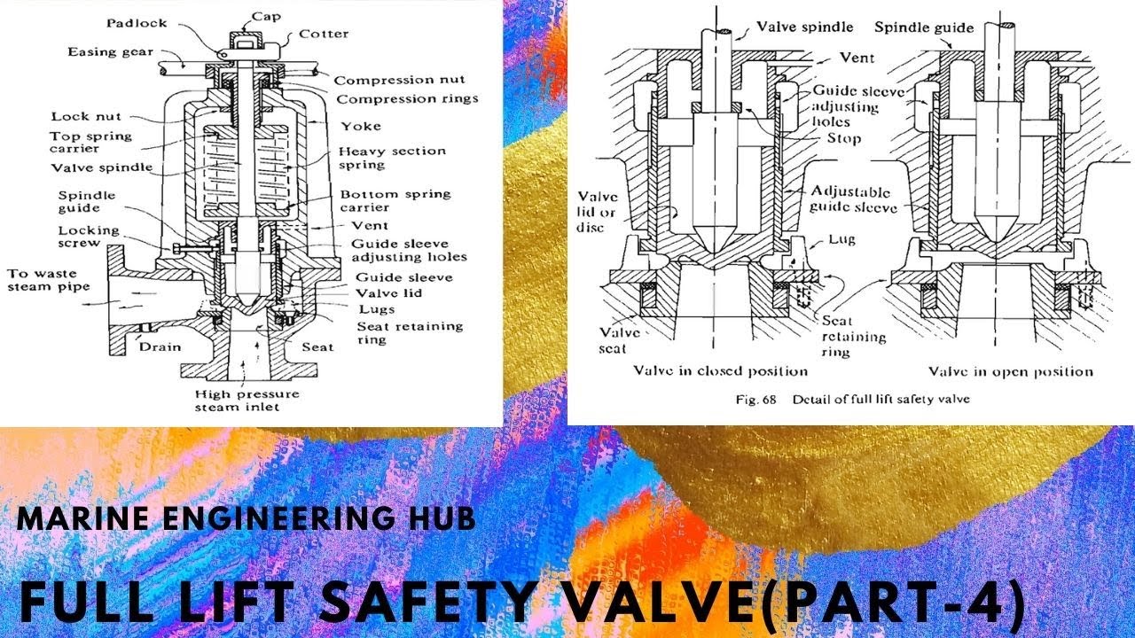
3.WHEN THE STEAM ACTS ON THE OPERATING PISTON IT CAUSES THE OPENING OF THE MAIN VALVE AGAINST THE SPRING PRESSURE. AS THE DIAMETER IS TWICE OF THE MAIN VALVE IT CAUSE THE D/4 LIFTING OF THE MAIN VALVE(i:e- FULL LIFT OF THE SAFETY VALVE).
Pig kind of a ball or bullet with diameter of the pipe is used to clean pipes where clogging or other such problems occur. If that is the case then reduced bore will cause the PIG to get stuck in it and cant be used .
It is difficult to sometimes get confirmation whether Pig would be used or not etc. so as Basis to move ahead we could check what piping dept. is taking in that line for their manual On-Off valves .
One approach is for Utility Services like water etc we can save costs and go for reduced bore but for line where process fluid will be used full bore valves could be selected
Many a times it is in the Client design basis, Example – few clients I have worked with wanted Full bore regardless of the service. But this is ok if it is EPCM project but when it’s a LSTK project every decision counts in money.
In reduced bore pressure drop is a concern that must also be taken in consideration while selecting though the pressure drop is not high it could have an impact

There is a wide range of safety valves available to meet the many different applications and performance criteria demanded by different industries. Furthermore, national standards define many varying types of safety valve.
The ASME standard I and ASME standard VIII for boiler and pressure vessel applications and the ASME/ANSI PTC 25.3 standard for safety valves and relief valves provide the following definition. These standards set performance characteristics as well as defining the different types of safety valves that are used:
ASME I valve - A safety relief valve conforming to the requirements of Section I of the ASME pressure vessel code for boiler applications which will open within 3% overpressure and close within 4%. It will usually feature two blowdown rings, and is identified by a National Board ‘V’ stamp.
ASME VIII valve- A safety relief valve conforming to the requirements of Section VIII of the ASME pressure vessel code for pressure vessel applications which will open within 10% overpressure and close within 7%. Identified by a National Board ‘UV’ stamp.
Full bore safety valve - A safety valve having no protrusions in the bore, and wherein the valve lifts to an extent sufficient for the minimum area at any section, at or below the seat, to become the controlling orifice.
Conventional safety relief valve -The spring housing is vented to the discharge side, hence operational characteristics are directly affected by changes in the backpressure to the valve.
Balanced safety relief valve -A balanced valve incorporates a means of minimising the effect of backpressure on the operational characteristics of the valve.
Pilot operated pressure relief valve -The major relieving device is combined with, and is controlled by, a self-actuated auxiliary pressure relief device.
Power-actuated safety relief valve - A pressure relief valve in which the major pressure relieving device is combined with, and controlled by, a device requiring an external source of energy.
Standard safety valve - A valve which, following opening, reaches the degree of lift necessary for the mass flowrate to be discharged within a pressure rise of not more than 10%. (The valve is characterised by a pop type action and is sometimes known as high lift).
Full lift (Vollhub) safety valve -A safety valve which, after commencement of lift, opens rapidly within a 5% pressure rise up to the full lift as limited by the design. The amount of lift up to the rapid opening (proportional range) shall not be more than 20%.
Direct loaded safety valve -A safety valve in which the opening force underneath the valve disc is opposed by a closing force such as a spring or a weight.
Proportional safety valve - A safety valve which opens more or less steadily in relation to the increase in pressure. Sudden opening within a 10% lift range will not occur without pressure increase. Following opening within a pressure of not more than 10%, these safety valves achieve the lift necessary for the mass flow to be discharged.
Diaphragm safety valve -A direct loaded safety valve wherein linear moving and rotating elements and springs are protected against the effects of the fluid by a diaphragm
Bellows safety valve - A direct loaded safety valve wherein sliding and (partially or fully) rotating elements and springs are protected against the effects of the fluids by a bellows. The bellows may be of such a design that it compensates for influences of backpressure.
Controlled safety valve - Consists of a main valve and a control device. It also includes direct acting safety valves with supplementary loading in which, until the set pressure is reached, an additional force increases the closing force.
Safety valve - A safety valve which automatically, without the assistance of any energy other than that of the fluid concerned, discharges a quantity of the fluid so as to prevent a predetermined safe pressure being exceeded, and which is designed to re-close and prevent further flow of fluid after normal pressure conditions of service have been restored. Note; the valve can be characterised either by pop action (rapid opening) or by opening in proportion (not necessarily linear) to the increase in pressure over the set pressure.
Direct loaded safety valve -A safety valve in which the loading due to the fluid pressure underneath the valve disc is opposed only by a direct mechanical loading device such as a weight, lever and weight, or a spring.
Assisted safety valve -A safety valve which by means of a powered assistance mechanism, may additionally be lifted at a pressure lower than the set pressure and will, even in the event of a failure of the assistance mechanism, comply with all the requirements for safety valves given in the standard.
Supplementary loaded safety valve - A safety valve that has, until the pressure at the inlet to the safety valve reaches the set pressure, an additional force, which increases the sealing force.
Note; this additional force (supplementary load), which may be provided by means of an extraneous power source, is reliably released when the pressure at the inlet of the safety valve reaches the set pressure. The amount of supplementary loading is so arranged that if such supplementary loading is not released, the safety valve will attain its certified discharge capacity at a pressure not greater than 1.1 times the maximum allowable pressure of the equipment to be protected.
Pilot operated safety valve -A safety valve, the operation of which is initiated and controlled by the fluid discharged from a pilot valve, which is itself, a direct loaded safety valve subject to the requirement of the standard.
The common characteristic shared between the definitions of conventional safety valves in the different standards, is that their operational characteristics are affected by any backpressure in the discharge system. It is important to note that the total backpressure is generated from two components; superimposed backpressure and the built-up backpressure:
Subsequently, in a conventional safety valve, only the superimposed backpressure will affect the opening characteristic and set value, but the combined backpressure will alter the blowdown characteristic and re-seat value.
The ASME/ANSI standard makes the further classification that conventional valves have a spring housing that is vented to the discharge side of the valve. If the spring housing is vented to the atmosphere, any superimposed backpressure will still affect the operational characteristics. Thiscan be seen from Figure 9.2.1, which shows schematic diagrams of valves whose spring housings are vented to the discharge side of the valve and to the atmosphere.
By considering the forces acting on the disc (with area AD), it can be seen that the required opening force (equivalent to the product of inlet pressure (PV) and the nozzle area (AN)) is the sum of the spring force (FS) and the force due to the backpressure (PB) acting on the top and bottom of the disc. In the case of a spring housing vented to the discharge side of the valve (an ASME conventional safety relief valve, see Figure 9.2.1 (a)), the required opening force is:
In both cases, if a significant superimposed backpressure exists, its effects on the set pressure need to be considered when designing a safety valve system.
Once the valve starts to open, the effects of built-up backpressure also have to be taken into account. For a conventional safety valve with the spring housing vented to the discharge side of the valve, see Figure 9.2.1 (a), the effect of built-up backpressure can be determined by considering Equation 9.2.1 and by noting that once the valve starts to open, the inlet pressure is the sum of the set pressure, PS, and the overpressure, PO.
Balanced safety valves are those that incorporate a means of eliminating the effects of backpressure. There are two basic designs that can be used to achieve this:
Although there are several variations of the piston valve, they generally consist of a piston type disc whose movement is constrained by a vented guide. The area of the top face of the piston, AP, and the nozzle seat area, AN, are designed to be equal. This means that the effective area of both the top and bottom surfaces of the disc exposed to the backpressure are equal, and therefore any additional forces are balanced. In addition, the spring bonnet is vented such that the top face of the piston is subjected to atmospheric pressure, as shown in Figure 9.2.2.
The bellows arrangement prevents backpressure acting on the upper side of the disc within the area of the bellows. The disc area extending beyond the bellows and the opposing disc area are equal, and so the forces acting on the disc are balanced, and the backpressure has little effect on the valve opening pressure.
Bellows failure is an important concern when using a bellows balanced safety valve, as this may affect the set pressure and capacity of the valve. It is important, therefore, that there is some mechanism for detecting any uncharacteristic fluid flow through the bellows vents. In addition, some bellows balanced safety valves include an auxiliary piston that is used to overcome the effects of backpressure in the case of bellows failure. This type of safety valve is usually only used on critical applications in the oil and petrochemical industries.
Since balanced pressure relief valves are typically more expensive than their unbalanced counterparts, they are commonly only used where high pressure manifolds are unavoidable, or in critical applications where a very precise set pressure or blowdown is required.
This type of safety valve uses the flowing medium itself, through a pilot valve, to apply the closing force on the safety valve disc. The pilot valve is itself a small safety valve.
The diaphragm type is typically only available for low pressure applications and it produces a proportional type action, characteristic of relief valves used in liquid systems. They are therefore of little use in steam systems, consequently, they will not be considered in this text.
The piston type valve consists of a main valve, which uses a piston shaped closing device (or obturator), and an external pilot valve. Figure 9.2.4 shows a diagram of a typical piston type, pilot operated safety valve.
The piston and seating arrangement incorporated in the main valve is designed so that the bottom area of the piston, exposed to the inlet fluid, is less than the area of the top of the piston. As both ends of the piston are exposed to the fluid at the same pressure, this means that under normal system operating conditions, the closing force, resulting from the larger top area, is greater than the inlet force. The resultant downward force therefore holds the piston firmly on its seat.
If the inlet pressure were to rise, the net closing force on the piston also increases, ensuring that a tight shut-off is continually maintained. However, when the inlet pressure reaches the set pressure, the pilot valve will pop open to release the fluid pressure above the piston. With much less fluid pressure acting on the upper surface of the piston, the inlet pressure generates a net upwards force and the piston will leave its seat. This causes the main valve to pop open, allowing the process fluid to be discharged.
When the inlet pressure has been sufficiently reduced, the pilot valve will reclose, preventing the further release of fluid from the top of the piston, thereby re-establishing the net downward force, and causing the piston to reseat.
Pilot operated safety valves offer good overpressure and blowdown performance (a blowdown of 2% is attainable). For this reason, they are used where a narrow margin is required between the set pressure and the system operating pressure. Pilot operated valves are also available in much larger sizes, making them the preferred type of safety valve for larger capacities.
One of the main concerns with pilot operated safety valves is that the small bore, pilot connecting pipes are susceptible to blockage by foreign matter, or due to the collection of condensate in these pipes. This can lead to the failure of the valve, either in the open or closed position, depending on where the blockage occurs.
The terms full lift, high lift and low lift refer to the amount of travel the disc undergoes as it moves from its closed position to the position required to produce the certified discharge capacity, and how this affects the discharge capacity of the valve.
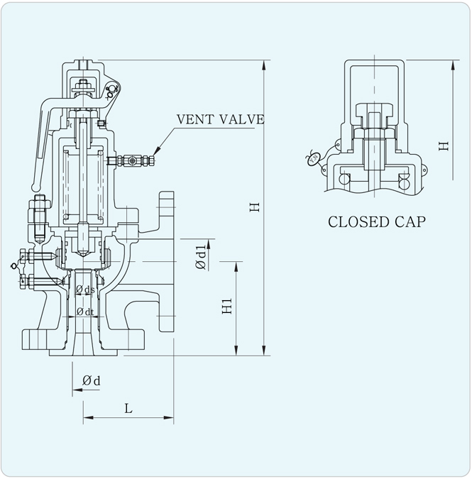
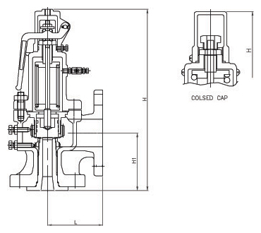
A full lift safety valve is one in which the disc lifts sufficiently, so that the curtain area no longer influences the discharge area. The discharge area, and therefore the capacity of the valve are subsequently determined by the bore area. This occurs when the disc lifts a distance of at least a quarter of the bore diameter. A full lift conventional safety valve is often the best choice for general steam applications.
The disc of a high lift safety valve lifts a distance of at least 1/12th of the bore diameter. This means that the curtain area, and ultimately the position of the disc, determines the discharge area. The discharge capacities of high lift valves tend to be significantly lower than those of full lift valves, and for a given discharge capacity, it is usually possible to select a full lift valve that has a nominal size several times smaller than a corresponding high lift valve, which usually incurs cost advantages.Furthermore, high lift valves tend to be used on compressible fluids where their action is more proportional.
In low lift valves, the disc only lifts a distance of 1/24th of the bore diameter. The discharge area is determined entirely by the position of the disc, and since the disc only lifts a small amount, the capacities tend to be much lower than those of full or high lift valves.
Except when safety valves are discharging, the only parts that are wetted by the process fluid are the inlet tract (nozzle) and the disc. Since safety valves operate infrequently under normal conditions, all other components can be manufactured from standard materials for most applications. There are however several exceptions, in which case, special materials have to be used, these include:
Cast steel -Commonly used on higher pressure valves (up to 40 bar g). Process type valves are usually made from a cast steel body with an austenitic full nozzle type construction.
For all safety valves, it is important that moving parts, particularly the spindle and guides are made from materials that will not easily degrade or corrode. As seats and discs are constantly in contact with the process fluid, they must be able to resist the effects of erosion and corrosion.
The spring is a critical element of the safety valve and must provide reliable performance within the required parameters. Standard safety valves will typically use carbon steel for moderate temperatures. Tungsten steel is used for higher temperature, non-corrosive applications, and stainless steel is used for corrosive or clean steam duty. For sour gas and high temperature applications, often special materials such as monel, hastelloy and ‘inconel’ are used.
Standard safety valves are generally fitted with an easing lever, which enables the valve to be lifted manually in order to ensure that it is operational at pressures in excess of 75% of set pressure. This is usually done as part of routine safety checks, or during maintenance to prevent seizing. The fitting of a lever is usually a requirement of national standards and insurance companies for steam and hot water applications. For example, the ASME Boiler and Pressure Vessel Code states that pressure relief valves must be fitted with a lever if they are to be used on air, water over 60°C, and steam.
A test gag (Figure 9.2.7) may be used to prevent the valve from opening at the set pressure during hydraulic testing when commissioning a system. Once tested, the gag screw is removed and replaced with a short blanking plug before the valve is placed in service.
The amount of fluid depends on the particular design of safety valve. If emission of this fluid into the atmosphere is acceptable, the spring housing may be vented to the atmosphere – an open bonnet. This is usually advantageous when the safety valve is used on high temperature fluids or for boiler applications as, otherwise, high temperatures can relax the spring, altering the set pressure of the valve. However, using an open bonnet exposes the valve spring and internals to environmental conditions, which can lead to damage and corrosion of the spring.
When the fluid must be completely contained by the safety valve (and the discharge system), it is necessary to use a closed bonnet, which is not vented to the atmosphere. This type of spring enclosure is almost universally used for small screwed valves and, it is becoming increasingly common on many valve ranges since, particularly on steam, discharge of the fluid could be hazardous to personnel.
Some safety valves, most commonly those used for water applications, incorporate a flexible diaphragm or bellows to isolate the safety valve spring and upper chamber from the process fluid, (see Figure 9.2.9).

Surface-controlled subsurface safety valves (SCSSVs) are critical components of well completions, preventing uncontrolled flow in the case of catastrophic damage to wellhead equipment. Fail-safe closure must be certain to ensure proper security of the well. However, this is not the only function in which it must be reliable—the valve must remain open to produce the well. Schlumberger surface controlled subsurface safety valves exceed all ISO 10432 and API Spec 14A requirements for pressure integrity, leakage acceptance criteria, and slam closure.
Through decades of innovation and experience, Schlumberger safety valve flapper systems are proven robust and reliable. The multizone dynamic seal technology for hydraulic actuation of subsurface safety valves is a further improvement in reliability performance when compared with traditional seal systems in the industry.
The multizone seal technology was developed and proved with exhaustive verification and validation of reliability, longevity, and performance. The validation methodology utilized a unique sapphire crystal bore, enabling the design team to view the seal’s dynamic and static performance in real time while simulating wellbore pressure and temperature conditions.
The multizone seal technology is currently available in the GeoGuard high-performance deepwater safety valves, which is validated to API Spec 14A V1 and V1-H.

of valve types has been developed. Examples of the common types are the ball valve, butterfly valve, globe valve, gate valve, plug valve, diaphragm valve, reducing valve, needle valve, check valve, and safety/relief valve. Each type
Besides the P/T value of the sleeve the limitations of the valve bodies also have to be considered. Please refer to the EN 12516-1 resp. ASME B16.34 in order to choose a proper pressure rating (PN/class). The shown values refer to austenitic stainless steel 1.4408 (A351 Gr. CF8M).
Gate valves are used to shut off the flow of fluid by inserting a rectangular gate or wedge into the path of a flowing fluid. Gate valves require very little space along the pipe axis and hardly restrict the flow of fluid when the gate is fully opened enabling gate valves to offer straightway flow with very little pressure drop. Gate valves are mostly used with larger pipe diameters (from 2″ to the largest pipelines) since they are less complex to construct than other types of valves in large sizes. More recently, however, the larger sizes have been supplemented by butterfly valves due to space limitations under which they are installed.
The gate valve, as illustrated in on the right, generally consists of a gate-like disc, actuated by a screwed stem and hand-wheel which moves up and down at right angles to the flow. In the closed position, the disc seats against two faces to shut off flow. To retain the fluid in the pipeline, a gland is provided which is supplied with some type of packing to resist leakage.
Gate valves consist of three major components: body, bonnet, and trim. The body is generally connected to the piping by means of flanged, screwed, or welded connections. The bonnet, containing the moving parts, is joined to the body, generally with bolts, to permit cleaning and maintenance. The valve trim consists of the stem, the gate, the wedge, or disc, and the seat rings.
The main operation mechanism is very simple. When the hand-wheel is turned, it rotates the stem, which is translated into the vertical movement of a gate via threads. They are considered multi-turn valves as it takes more than one 360° turn to fully open/close the valve. When the gate is lifted from the path of the flow, the valve opens and when it returns to its closed position, it seals the bore resulting in a full closure of the valve.
The closing member, sometimes referred as gate also, comes in a variety of designs and technologies to produce effective sealing for differing applications. There are usually two types of gate valve closing members which are having further varieties.
Parallel gate valves have a parallel faced gate like closing member. This closing member may consists of a single disc or twin discs with a spreading mechanism in between. The force that presses the disc against the seat is controlled by the fluid pressure acting on either a floating disc or a floating seat. Because the disc slides across the seat face, parallel gate valves are also capable of handling fluids, which carry solids in suspension.
In a conventional parallel slide gate valve the closure member consists of two discs with springs in between. The duties of these springs are to keep the upstream and downstream seating’s in sliding contact and to improve the seating load at low fluid pressures. The discs are carried in a belt eye in a manner that prevents their unrestrained spreading as they move into the fully open valve position.
The advantages offered by this construction include not only economy of construction but also a reduced operating effort and lower maintenance cost. The only disadvantage is a slight increase in pressure loss across the valve.
Through-conduit gate valves are one-unit gates that include a bore size hole as shown in figure on the right. In open state, the bore size hole is aligned with the two seat rings to create a smooth flow with minimal turbulence. This special design allows for minimal pressure loss on the system and is perfect for transportation of crude oil and natural gas liquids (NGLs). The valve seats remain clean, however, the disc cavity can capture foreign material. Therefore, the cavity typically has a built-in plug for maintenance purposes of draining the accumulated foreign material.
These valves are used in pipelines where pigs are run through the piping to perform cleaning of built-up deposits or debris. The typical applications of conduit valves include dirty river water with suspended solids or water with sludge or debris.
Knife Gate Valves are a specific type of parallel gate valve and is designed to handle systems with high content of suspended solids. The knife gate valves are especially beneficial for handling slurry, viscous, corrosive and abrasive media. The valve owes its ability to handle these fluids to the knife-edged disc, which is capable of cutting through fibrous material, and the virtual absence of a valve body cavity. The disc travels in lateral guides and is forced against the seat by lugs at the bottom. If a high degree of fluid tightness is required, the valve may also be provided with an O-ring seat seal.
The valves find application in paper and pulp, minerals and metals, steel plants, thermal power plants and chemical/ petrochemical industries. Knife gate valve has a short face-to-face length compared to other gate valves. As a consequence a knife gate valve is light weighted compared to other gate valves.
Wedge gate valves differ from parallel gate valves in that the closure member is wedge-shaped instead of parallel. The purpose of the wedge shape is to introduce a high supplementary seating load that enables wedge gate valves to seal not only against high, but also low, fluid pressures. The degree of seat tightness that can be achieved with wedge gate valves is therefore potentially higher than with conventional parallel gate valves.
Efforts to improve the performance of wedge gate valves led to the development of a variety of wedge designs; the most common ones are described in the following section.
Solid or plain wedge is most common & widely used disk types because of its simplicity and strength. It can be of solid or hollow construction. This design has the advantage of being simple and robust, but distortions of the valve body due to thermal and pipeline stresses may unseat or jam the metal seated wedge making it more susceptible to leakage. A valve with solid wedge may be installed in any position, and it is suitable for almost all fluids. It can be used in turbulent flow also. Solid wedge is subjected to thermal locking if used in high-temperature service.
Thermal locking is a phenomenon in which wedge is stuck between the seats due to the expansion of the metal. Solid-wedge gate valves are generally used in moderate to lower pressure-temperature applications.
Split wedge disk consists of two solid pieces and holds together with the help of special mechanism like a spacer ring or spring. To keep the plates together, the body has grooves in which the wedge assembly travels.Split wedge is self-adjusting and self aligning to both seats sides. Disk flexibility is inherent to the split wedge design. This flexibility allows the split wedge to seal more easily and it reduces stickiness between the sealing surfaces in cases where the valve seats are angularly misaligned. The mismatched angle is also designed with some free movement to allow the seating surfaces to match with each other.
Rising stems are fixed to the gate and they rise and lower together as the valve is operated, providing a visual indication of the valve position and making it possible to grease the stem. A nut rotates around the threaded stem and moves it. This type of valve has an inside screwed stem and the packing is subjected to wear because of the up and down movement and turning motion of the stem. This type is only suitable for above-ground installation.
Non-rising stems are threaded into the gate, and rotate with the wedge rising and lowering inside the valve. Rotation of the wheel operates the valve, but the stem does not come out of the housing. They take up less vertical space since the stem is kept within the valve body. Non-rising valves are almost always fitted with a local visual pointer which indicates the position of the valve. Gate valves with non-rising stems are suitable for both above-ground and underground installations.
A metal seated gate valve has a depression in the valve bottom. The conical wedge fits into the depression in the valve bottom to ensure a tight closure. Herewith, sand and pebbles are embedded in the bore. The pipe system will never be completely free from impurities regardless of how thoroughly the pipe is flushed upon installation or repair. Thus any metal wedge will eventually lose its ability to be drop-tight.
A resilient seated gate valve has a plain valve bottom allowing free passage for sand and pebbles in the valve. If impurities pass as the valve closes, the rubber surface will close around the impurities while the valve is closed. A high-quality rubber compound absorbs the impurities as the valve closes, and the impurities will be flushed away when the valve is opened again. The rubber surface will regain its original shape securing a drop-tight sealing.
Gate valves meet the majority of valve requirements in process piping and are considered one of the most used valves of all the valves employed in refineries, petrochemical, and gas processing plants where pressure remains relatively low, but temperature may be very high. They are suitable for most fluids including steam, water, oil, air, and gas.
Gate valves are designed for fully open or fully closed service. They are installed in pipelines as isolating valves, and should not be used as flow control or regulating valves. When operating the valve stem, the gate moves up- or downwards on the threaded part of the stem.
Gate valves are often used when minimum pressure loss and a free bore is needed. When fully open, a typical gate valve has no obstruction in the flow path resulting in a very low pressure loss, and this design makes it possible to use a pipe-cleaning pig. A gate valve is a multiturn valve meaning that the operation of the valve is done by means of a threaded stem. As the valve has to turn multiple times to go from open to closed position, the slow operation also prevents water hammer effects.
At high pressures, friction can become a problem. The seating load of the larger gate valves (except those with floating seats) can become so high at high fluid pressures that friction between the seating’s can make it difficult to raise the disc from the closed position. Such large gate valves are therefore frequently provided with a valved bypass line, which is used to relieve the seating load prior to opening the valve.
Sometimes during the operation of gate valves, thermal expansion of a liquid trapped in the closed valve chamber will force the upstream and downstream discs into more intimate contact with their seats, and cause the pressure in the valve chamber to rise. The higher seating stress makes it in turn more difficult to raise the discs, and the pressure in the valve chamber may quickly become high enough to cause a bonnet flange joint to leak or the valve body to deform. Thus, if gate valves are used to handle a liquid with high thermal expansion, they must have a pressure-equalizing connection that connects the valve chamber with the upstream piping. The pressure-equalizing connection may be provided by a hole in the upstream disc or by other internal or external means.

A variety of valves are used in the piping and machinery systems of the ship as per the need of the flow pattern of the liquid. All valves used on ships have the basic functionality of regulating the flow of the liquid in the pipes.
Valves are used for almost all machinery systems on ships for controlling and regulating fluid through pipes. Although valves are known as efficiency decreasing device as they reduce the energy in the liquid flow, their use is imperative in applications where limited flow is required.
Therefore, for any aspiring or serving marine engineer, it is extremely necessary to know about construction and working of various types of valves used on ships.
As the name suggests, a gate valve consists of a simple mechanism called as “the gate” or the valve disc, which performs the main function of regulating the flow of the fluid. However, it is to note that the gate valve can have only no-flow or full-flow condition and thus can only be operated in one position. The valve gives a full bore flow without change of direction.
The working of the gate valves is pretty simple as it does not involve any complex mechanism. The spindle wheel, which is attached to the spindle rod, is rotated to move the “gate” at right angle to the flow of the fluid. The screwed spindle works in a nut and lifts the valve to open or close the “gate” between the circular openings furnished with seats. The valves and the seats may be either tapered or parallel on their facing sides.
Gate valves are classified on the basis of their internal operation and the stem type. There are two important types of gate valves with respect to stem operation:
In rising stem gate valve, the stem has threads, which are mated with the integral thread of the yoke or within the bonnet. When the valve is operated, the stem rises above the actuator and the valve attached to the stem opens up.
In this type of gate valve, the gate or the valve disc is itself internally threaded and connected to the stem. As the stem thread mates with the disc, the valve will open or close without raising the stem as in the above type.
As the valve disc (gate) directly works against the flow of the fluid, the metal surface undergoes wear and tear. This often results in leaking of the valve.
Gland packing is used in the gate valve to stop any kind of water leakage through the space around the spindle. The gland packing also gets damaged in the long run and thus has to changed at regular intervals of time.
Uses: Gate valves are used in applications requiring minimum pressure loss. They are also used in applications wherein bidirectional flow is required.


 8613371530291