
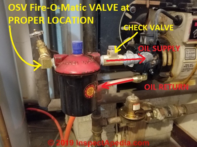
furnace safety valve manufacturer

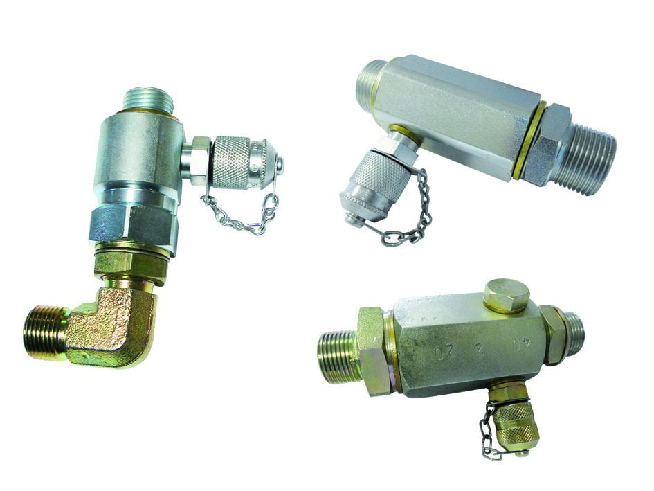
Distributor of hydraulic press safety, quick opening safety, rotary and safety valves. Amerigear®, Boston Gear®, Carlisle®, DeMag®, Desch® and IMI Norgren®, pneumatic, double action, quick release and flow control valves also provided. Repair and preventative maintenance services are offered. Value added services such as custom barcoding, CAD capabilities, OEM assembly, plant surveys and third party logistics are also available. Serves the metal processing, metal service center, paper mill and paper converting, canning, grinding, commercial laundry, marine, oil and gas and material handling industries. Vendor managed inventory (VMI) programs available. Kanban delivery.

The S100 Safety Shut Off valve is mainly used to avoid any damage to components as well as to avoid too high or too low pressure in the gas train. This could cause high financial losses and/or injured ...
130 Series Safety valves are also available as Relief valves. Relief valves, identified by the letter R after the type number, are devices with an operational function, ...
Parker"s cartridge safety relief valves (CSRV) are designed to offer the highest level of protection while maintaining easy serviceability. The CSRV was designed from the existing Parker ...
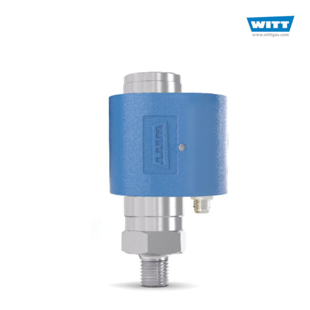
WITT is a manufacturer of Pressure relief valvesor Safety relief valves for technical gases. They are designed to protect against overpressure by discharging pressurized gases and vapors from pipelines, pressure vessels and plant components. Safety relief valves (SRV) are often the last line of defense against explosion – and such an explosion could be fatal. Other common names for safety relief valves are pressure relief valve (PRV), safety valve, pressure safety valve, overpressure valve, relief valve or blow-off valve.
WITT safety valves are very precise. They are individually preset to open at a predetermined pressure within the range 0.07 to 652 Psi. Their small size and orientation-independent installation allow a wide range of connection options. WITT relief valves also stand out due to their high blow-off flow rates of up to 970m³/h. They can be used within a temperature range of -76° F to +518°F and even with very low pressures.
For maximum safety, WITT undertakes 100 % testing of each safety relief valve before it is delivered. In addition, WITT offers individual testing of eachsafety valveby the TÜV, with their certificate as proof of the correct set pressure.
WITTsafety relief valvesare direct-acting, spring-loaded valves. When the preset opening pressure is reached, a spring-loaded element in the valve gives way and opens, and the pressure is relieved. Once the pressures are equalized, the valve closes automatically and can be reactivated any time the pressure rises again. Depending on the application and the nature of the gas, the safety relief valvescan either discharge to atmosphere, or via a connected blow-off line. The opening pressure of the safety valves is preset by WITT at the factory according to the customer’s requirements.
Safety relief valvesare used in numerous industries and industrial applications where, for example, gases pass through pipelines or where special process vessels have to be filled with gas at a certain pressure.
These include, among other things:Pipeline, plant and container constructionIndustrial furnace constructionInsulators and reactors (e.g. “glovebox” systems)hydrogen-powered vehiclesAdditive manufacturing (3D printer)
For most industrial applications using technical gases, brass is usually the standard material of construction of thesafety relief valvebody/housing. For the use of pressure relief valves with aggressive and corrosive gases, the housings are made of high-quality stainless steel (1.4541/AISI 321, 1.4404/AISI 316L, 1.4305/AISI 303 or 1.4571/AISI 316Ti). The use of aluminium as a housing material is also possible.
Depending on the type of gas used and individual customer requirements, various sealing materials and elastomers are available to ensure the safety of your systems under even the most difficult conditions.
WITT pressure relief valves are available with different connections. In addition to the standard versions with the usual internal or external threads, special versions with KF or CF flanges, VCR or UNF threads can also be ordered. Special adapters for connecting the safety relief valve to a blow-off line are also available.
Gas Safety ValvesThese valves automatically control main gas flow. Our automatic pilot valves shut off both the main and pilot gases. Pilot gas is tapped from the main line within the control. Gas will flow only to the pilot burner when the reset button is depressed. The manual pilot valve stop can be adjusted for maximum pilot flow.

Relief valves are designed to open at a preset pressure (or temperature) level and relieve the system when it has exceeded the desired level. The valve"s relief of elevated liquid, gas, or steam pressures prevents damage to the system. We offer a wide selection of relief valves for any application.

There is a wide range of safety valves available to meet the many different applications and performance criteria demanded by different industries. Furthermore, national standards define many varying types of safety valve.
The ASME standard I and ASME standard VIII for boiler and pressure vessel applications and the ASME/ANSI PTC 25.3 standard for safety valves and relief valves provide the following definition. These standards set performance characteristics as well as defining the different types of safety valves that are used:
ASME I valve - A safety relief valve conforming to the requirements of Section I of the ASME pressure vessel code for boiler applications which will open within 3% overpressure and close within 4%. It will usually feature two blowdown rings, and is identified by a National Board ‘V’ stamp.
ASME VIII valve- A safety relief valve conforming to the requirements of Section VIII of the ASME pressure vessel code for pressure vessel applications which will open within 10% overpressure and close within 7%. Identified by a National Board ‘UV’ stamp.
Full bore safety valve - A safety valve having no protrusions in the bore, and wherein the valve lifts to an extent sufficient for the minimum area at any section, at or below the seat, to become the controlling orifice.
Conventional safety relief valve -The spring housing is vented to the discharge side, hence operational characteristics are directly affected by changes in the backpressure to the valve.
Balanced safety relief valve -A balanced valve incorporates a means of minimising the effect of backpressure on the operational characteristics of the valve.
Pilot operated pressure relief valve -The major relieving device is combined with, and is controlled by, a self-actuated auxiliary pressure relief device.
Power-actuated safety relief valve - A pressure relief valve in which the major pressure relieving device is combined with, and controlled by, a device requiring an external source of energy.
Standard safety valve - A valve which, following opening, reaches the degree of lift necessary for the mass flowrate to be discharged within a pressure rise of not more than 10%. (The valve is characterised by a pop type action and is sometimes known as high lift).
Full lift (Vollhub) safety valve -A safety valve which, after commencement of lift, opens rapidly within a 5% pressure rise up to the full lift as limited by the design. The amount of lift up to the rapid opening (proportional range) shall not be more than 20%.
Direct loaded safety valve -A safety valve in which the opening force underneath the valve disc is opposed by a closing force such as a spring or a weight.
Proportional safety valve - A safety valve which opens more or less steadily in relation to the increase in pressure. Sudden opening within a 10% lift range will not occur without pressure increase. Following opening within a pressure of not more than 10%, these safety valves achieve the lift necessary for the mass flow to be discharged.
Diaphragm safety valve -A direct loaded safety valve wherein linear moving and rotating elements and springs are protected against the effects of the fluid by a diaphragm
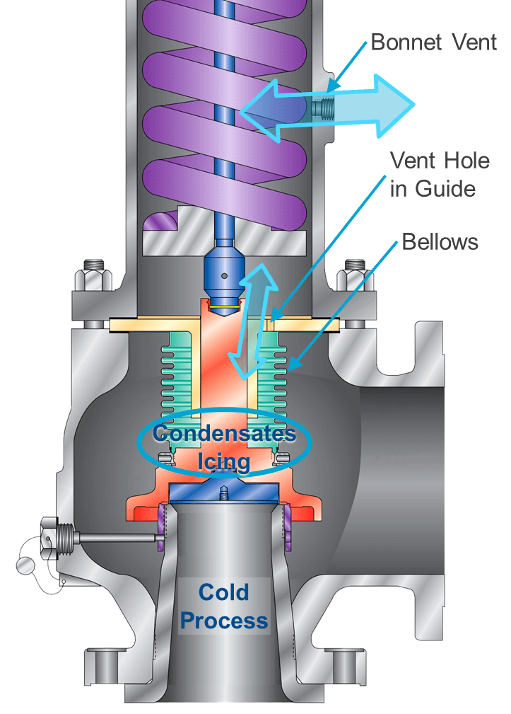
Bellows safety valve - A direct loaded safety valve wherein sliding and (partially or fully) rotating elements and springs are protected against the effects of the fluids by a bellows. The bellows may be of such a design that it compensates for influences of backpressure.
Controlled safety valve - Consists of a main valve and a control device. It also includes direct acting safety valves with supplementary loading in which, until the set pressure is reached, an additional force increases the closing force.
Safety valve - A safety valve which automatically, without the assistance of any energy other than that of the fluid concerned, discharges a quantity of the fluid so as to prevent a predetermined safe pressure being exceeded, and which is designed to re-close and prevent further flow of fluid after normal pressure conditions of service have been restored. Note; the valve can be characterised either by pop action (rapid opening) or by opening in proportion (not necessarily linear) to the increase in pressure over the set pressure.
Direct loaded safety valve -A safety valve in which the loading due to the fluid pressure underneath the valve disc is opposed only by a direct mechanical loading device such as a weight, lever and weight, or a spring.
Assisted safety valve -A safety valve which by means of a powered assistance mechanism, may additionally be lifted at a pressure lower than the set pressure and will, even in the event of a failure of the assistance mechanism, comply with all the requirements for safety valves given in the standard.
Supplementary loaded safety valve - A safety valve that has, until the pressure at the inlet to the safety valve reaches the set pressure, an additional force, which increases the sealing force.
Note; this additional force (supplementary load), which may be provided by means of an extraneous power source, is reliably released when the pressure at the inlet of the safety valve reaches the set pressure. The amount of supplementary loading is so arranged that if such supplementary loading is not released, the safety valve will attain its certified discharge capacity at a pressure not greater than 1.1 times the maximum allowable pressure of the equipment to be protected.
Pilot operated safety valve -A safety valve, the operation of which is initiated and controlled by the fluid discharged from a pilot valve, which is itself, a direct loaded safety valve subject to the requirement of the standard.
The common characteristic shared between the definitions of conventional safety valves in the different standards, is that their operational characteristics are affected by any backpressure in the discharge system. It is important to note that the total backpressure is generated from two components; superimposed backpressure and the built-up backpressure:
Subsequently, in a conventional safety valve, only the superimposed backpressure will affect the opening characteristic and set value, but the combined backpressure will alter the blowdown characteristic and re-seat value.
The ASME/ANSI standard makes the further classification that conventional valves have a spring housing that is vented to the discharge side of the valve. If the spring housing is vented to the atmosphere, any superimposed backpressure will still affect the operational characteristics. Thiscan be seen from Figure 9.2.1, which shows schematic diagrams of valves whose spring housings are vented to the discharge side of the valve and to the atmosphere.
By considering the forces acting on the disc (with area AD), it can be seen that the required opening force (equivalent to the product of inlet pressure (PV) and the nozzle area (AN)) is the sum of the spring force (FS) and the force due to the backpressure (PB) acting on the top and bottom of the disc. In the case of a spring housing vented to the discharge side of the valve (an ASME conventional safety relief valve, see Figure 9.2.1 (a)), the required opening force is:
In both cases, if a significant superimposed backpressure exists, its effects on the set pressure need to be considered when designing a safety valve system.
Once the valve starts to open, the effects of built-up backpressure also have to be taken into account. For a conventional safety valve with the spring housing vented to the discharge side of the valve, see Figure 9.2.1 (a), the effect of built-up backpressure can be determined by considering Equation 9.2.1 and by noting that once the valve starts to open, the inlet pressure is the sum of the set pressure, PS, and the overpressure, PO.
Balanced safety valves are those that incorporate a means of eliminating the effects of backpressure. There are two basic designs that can be used to achieve this:
Although there are several variations of the piston valve, they generally consist of a piston type disc whose movement is constrained by a vented guide. The area of the top face of the piston, AP, and the nozzle seat area, AN, are designed to be equal. This means that the effective area of both the top and bottom surfaces of the disc exposed to the backpressure are equal, and therefore any additional forces are balanced. In addition, the spring bonnet is vented such that the top face of the piston is subjected to atmospheric pressure, as shown in Figure 9.2.2.
The bellows arrangement prevents backpressure acting on the upper side of the disc within the area of the bellows. The disc area extending beyond the bellows and the opposing disc area are equal, and so the forces acting on the disc are balanced, and the backpressure has little effect on the valve opening pressure.
Bellows failure is an important concern when using a bellows balanced safety valve, as this may affect the set pressure and capacity of the valve. It is important, therefore, that there is some mechanism for detecting any uncharacteristic fluid flow through the bellows vents. In addition, some bellows balanced safety valves include an auxiliary piston that is used to overcome the effects of backpressure in the case of bellows failure. This type of safety valve is usually only used on critical applications in the oil and petrochemical industries.
Since balanced pressure relief valves are typically more expensive than their unbalanced counterparts, they are commonly only used where high pressure manifolds are unavoidable, or in critical applications where a very precise set pressure or blowdown is required.
This type of safety valve uses the flowing medium itself, through a pilot valve, to apply the closing force on the safety valve disc. The pilot valve is itself a small safety valve.
The diaphragm type is typically only available for low pressure applications and it produces a proportional type action, characteristic of relief valves used in liquid systems. They are therefore of little use in steam systems, consequently, they will not be considered in this text.
The piston type valve consists of a main valve, which uses a piston shaped closing device (or obturator), and an external pilot valve. Figure 9.2.4 shows a diagram of a typical piston type, pilot operated safety valve.
The piston and seating arrangement incorporated in the main valve is designed so that the bottom area of the piston, exposed to the inlet fluid, is less than the area of the top of the piston. As both ends of the piston are exposed to the fluid at the same pressure, this means that under normal system operating conditions, the closing force, resulting from the larger top area, is greater than the inlet force. The resultant downward force therefore holds the piston firmly on its seat.
If the inlet pressure were to rise, the net closing force on the piston also increases, ensuring that a tight shut-off is continually maintained. However, when the inlet pressure reaches the set pressure, the pilot valve will pop open to release the fluid pressure above the piston. With much less fluid pressure acting on the upper surface of the piston, the inlet pressure generates a net upwards force and the piston will leave its seat. This causes the main valve to pop open, allowing the process fluid to be discharged.
When the inlet pressure has been sufficiently reduced, the pilot valve will reclose, preventing the further release of fluid from the top of the piston, thereby re-establishing the net downward force, and causing the piston to reseat.
Pilot operated safety valves offer good overpressure and blowdown performance (a blowdown of 2% is attainable). For this reason, they are used where a narrow margin is required between the set pressure and the system operating pressure. Pilot operated valves are also available in much larger sizes, making them the preferred type of safety valve for larger capacities.
One of the main concerns with pilot operated safety valves is that the small bore, pilot connecting pipes are susceptible to blockage by foreign matter, or due to the collection of condensate in these pipes. This can lead to the failure of the valve, either in the open or closed position, depending on where the blockage occurs.
The terms full lift, high lift and low lift refer to the amount of travel the disc undergoes as it moves from its closed position to the position required to produce the certified discharge capacity, and how this affects the discharge capacity of the valve.
A full lift safety valve is one in which the disc lifts sufficiently, so that the curtain area no longer influences the discharge area. The discharge area, and therefore the capacity of the valve are subsequently determined by the bore area. This occurs when the disc lifts a distance of at least a quarter of the bore diameter. A full lift conventional safety valve is often the best choice for general steam applications.
The disc of a high lift safety valve lifts a distance of at least 1/12th of the bore diameter. This means that the curtain area, and ultimately the position of the disc, determines the discharge area. The discharge capacities of high lift valves tend to be significantly lower than those of full lift valves, and for a given discharge capacity, it is usually possible to select a full lift valve that has a nominal size several times smaller than a corresponding high lift valve, which usually incurs cost advantages.Furthermore, high lift valves tend to be used on compressible fluids where their action is more proportional.
In low lift valves, the disc only lifts a distance of 1/24th of the bore diameter. The discharge area is determined entirely by the position of the disc, and since the disc only lifts a small amount, the capacities tend to be much lower than those of full or high lift valves.
Except when safety valves are discharging, the only parts that are wetted by the process fluid are the inlet tract (nozzle) and the disc. Since safety valves operate infrequently under normal conditions, all other components can be manufactured from standard materials for most applications. There are however several exceptions, in which case, special materials have to be used, these include:
Cast steel -Commonly used on higher pressure valves (up to 40 bar g). Process type valves are usually made from a cast steel body with an austenitic full nozzle type construction.
For all safety valves, it is important that moving parts, particularly the spindle and guides are made from materials that will not easily degrade or corrode. As seats and discs are constantly in contact with the process fluid, they must be able to resist the effects of erosion and corrosion.
The spring is a critical element of the safety valve and must provide reliable performance within the required parameters. Standard safety valves will typically use carbon steel for moderate temperatures. Tungsten steel is used for higher temperature, non-corrosive applications, and stainless steel is used for corrosive or clean steam duty. For sour gas and high temperature applications, often special materials such as monel, hastelloy and ‘inconel’ are used.
Standard safety valves are generally fitted with an easing lever, which enables the valve to be lifted manually in order to ensure that it is operational at pressures in excess of 75% of set pressure. This is usually done as part of routine safety checks, or during maintenance to prevent seizing. The fitting of a lever is usually a requirement of national standards and insurance companies for steam and hot water applications. For example, the ASME Boiler and Pressure Vessel Code states that pressure relief valves must be fitted with a lever if they are to be used on air, water over 60°C, and steam.
A test gag (Figure 9.2.7) may be used to prevent the valve from opening at the set pressure during hydraulic testing when commissioning a system. Once tested, the gag screw is removed and replaced with a short blanking plug before the valve is placed in service.
The amount of fluid depends on the particular design of safety valve. If emission of this fluid into the atmosphere is acceptable, the spring housing may be vented to the atmosphere – an open bonnet. This is usually advantageous when the safety valve is used on high temperature fluids or for boiler applications as, otherwise, high temperatures can relax the spring, altering the set pressure of the valve. However, using an open bonnet exposes the valve spring and internals to environmental conditions, which can lead to damage and corrosion of the spring.
When the fluid must be completely contained by the safety valve (and the discharge system), it is necessary to use a closed bonnet, which is not vented to the atmosphere. This type of spring enclosure is almost universally used for small screwed valves and, it is becoming increasingly common on many valve ranges since, particularly on steam, discharge of the fluid could be hazardous to personnel.
Some safety valves, most commonly those used for water applications, incorporate a flexible diaphragm or bellows to isolate the safety valve spring and upper chamber from the process fluid, (see Figure 9.2.9).

L&L Special Furnace Co., Inc. has delivered a high-uniformity box furnace to a worldwide, leading valve manufacturer located in the southeastern United States.
The control system is driven by a Honeywell program control with an overtemperature control to prevent the furnace from overfiring. A digital round single-input chart recorder keeps accurate recordings of the furnace process temperature. The Kanthal Iron Aluminum Chrome coiled elements located on the sides, back, and door are controlled in two zones for the balancing of temperature gradients from top to bottom.
All L&L furnaces can be configured with various options and be specifically tailored to meet your thermal needs. We also offer furnaces equipped with pyrometry packages to meet the latest revision of ASM2750.
One of the most critical components on any vacuum furnace is the pressure relief valve. While its function is clear, the fact that it needs to be inspected – and tested is either not well understood or simply ignored. Normally positioned atop a vacuum furnace (Fig. 1) it is in an area that is not always conducive to maintenance, and complicated in many instances by the fact that only the manufacturer can service them.
A pressure relief valve is a safety device designed to protect a vacuum furnace from over-pressurization. An overpressure event refers to any condition that would cause the pressure to increase beyond the specified design pressure (the so-called maximum allowable working pressure or MAWP). The pressure relief valve is an integral part of the safety system provided on most vacuum furnaces. Vacuum vessels, including evacuated chambers and associated piping, pose a potential hazard to personnel and the equipment itself from collapse, rupture, or implosion.
Pressure relief valves are mandatory on any vacuum furnace system using pressurized gas and operating (including gas quenching operations) over 103.4 Pa (15 psig). In addition, vacuum vessels and ancillary equipment (e.g., accumulator or surge tanks, gas storage systems including dewars, air compressors,) must be designed to ensure that allowable stresses are not exceeded and to ensure that the vessel is stable (resistant to buckling). Since pressure relief valves are safety devices, there are numerous international codes and standards written to control their design and application.
In most countries, manufacturers are legally required to protect pressure vessels and other equipment by installing relief valves. In most countries, equipment design codes are provided by organizations such as ASME (e.g., BPVC), ISO (e.g., ISO 4126), European Standard (e.g. EN-764-7) and API recommended practices to name a few. These standards are mandatory and their design standards must be complied with for all relief valves.
The ASME Boiler and Pressure Vessel Code (BPVC) is unique in the United States and Canada, having been adopted by the majority of state and provincial legislatures and mandated by law. Compliance with this code is mandatory for vessels with an external pressure not exceeding 103.4 Pa (15 psig) under Section VIII Paragraph U-1(c)(2)(h), but the design rules may be applied to all vacuum furnaces. Under Section VIII, Paragraph UG-28(f), such vessels may be code stamped. Also, any repairs to or modifications of the pressure vessel require recertification.
The most widely used voluntary standards for pressure vessels (in the United States) are published by the American Petroleum Institute (API). These Standards provide recommended practices for pressure relief valve construction, sizing, installation and maintenance and are a good source for general knowledge.
There are a number of different types of pressure relief devices (e.g. pressure and temperature safety relief valves, steam or vapor relief valves, liquid safety valves, safety relief valves, rupture discs), the choice of which most often depends on the application use.
Most vacuum furnace pressure relief valves are spring-loaded devices (Fig. 2). Essentially, the valve consists of a housing with an inlet nozzle mounted on the vacuum furnace (or other pressurized components), a disc held against the nozzle to prevent flow under normal system operating conditions, a spring to hold the disc closed, and a body/bonnet to contain the operating elements. The spring load is adjustable to vary the pressure at which the valve will open.
In high-pressure gas systems, it is recommended that the outlet of the relief valve is unrestricted, discharging into the room. However, there are exceptions such as furnaces running combustible gases (e.g., hydrogen partial pressure or process gas or acetylene for low-pressure vacuum carburizing). In systems where the outlet is connected to piping, the opening of a relief valve will give a pressure build-up in the piping system downstream of the relief valve. This often means that the relief valve will not re-seat once the set pressure is reached. For these systems so-called “differential” relief valves are often used. This means that the pressure is only working on an area that is much smaller than the opening area of the valve. If the valve is opened the pressure has to decrease enormously before the valve closes and the outlet pressure of the valve can easily keep the valve open. Another consideration is that if other relief valves are connected to the outlet pipe system, they may open as the pressure in the exhaust pipe system increases. This may cause undesired operation.
Another important consideration in the design of a pressure relief valve is the ability to maintain a tight seal (leaky valve will often “hiss” as pressurized gas escapes). Leakage is common on valves that have been triggered by a pressure event. Since pressure relief valves are required to remain on systems for many, many years under a wide variety of furnace pressure and temperature conditions, a small leakage will often result in progressive damage to the valve seating surfaces. Extreme leakage can even result in the premature opening of the valve and destroy the ability to maintain pressure within the vacuum system. Allowable seat leakage limits for pressure relief valves are many orders of magnitude more stringent than required for other types of valves. These extremes of tightness are achieved by close control of part alignment, optically flat seating surfaces, and careful selection of materials for each application.
A well thought out and strictly adhered to maintenance schedule based on the manufacturer’s instructions must be carried out in the field to ensure the valve will operate properly when called on to do so. Inspecting the integrity of the value (and in particular that it is leak-tight) is mandatory. Most pressure relief valves on vacuum furnace systems are so-called “one and done” discharge devices and as such are not cycled or cycle checked. If a pressure relief valve does discharge, in most cases it cannot be reset in the field (check the valves operating instructions!) and needs to be returned to the factory for inspection and testing. Pressure relief valves should also be factory tested and calibrated annually or on a time schedule recommended by the manufacturer. As such, it is always a good idea to have a spare valve of the proper size on hand.
Most manufacturers recommend that the system operating pressures not exceed 90% of set pressure to achieve and maintain proper seat tightness integrity. Since pressure relief valves are normally supplied by the OEM (original equipment manufacturer) it is important to understand the design parameters and service restrictions that have been selected by them.
Once a condition occurs that causes the pressure in a system or vessel to increase to a dangerous level, the pressure relief valve may be the only device remaining to prevent a catastrophic failure. Since reliability is directly related to the complexity of the device, it is important that the design of the pressure relief valve be as simple as possible.
The pressure relief valve must open at a predetermined set pressure, flow a rated capacity at a specified overpressure, and close when the system pressure has returned to a safe level. Pressure relief valves must be designed with materials compatible with the gas (or liquid in some cases), from simple nitrogen or argon to potentially more corrosive fluids. They must also be designed to operate in a consistently smooth and stable manner on a variety of fluids and fluid phases.
During the inspection of a vacuum furnace, the individuals involved should be familiar with the pressure relief device installed on the furnace and its associated equipment. Some of the things to look for in an inspection are the following:
Compare the device nameplate set pressure with the maximum allowable working pressure and ensure the device set pressure does not exceed the valve rating. A device with a set pressure less than MAWP is acceptable. If multiple devices are used, at least one must have a set pressure equal to or less than the MAWP. The ASME Code should be reviewed for other conditions relating to the use of multiple devices.
Pressure relief valves are one of the most oft times overlooked safety devices installed on vacuum furnaces. The reader is challenged to go out to their equipment, find and read the manufacturer’s recommendations as to the operation, inspection, maintenance, and testing of these devices. You will be glad you did.
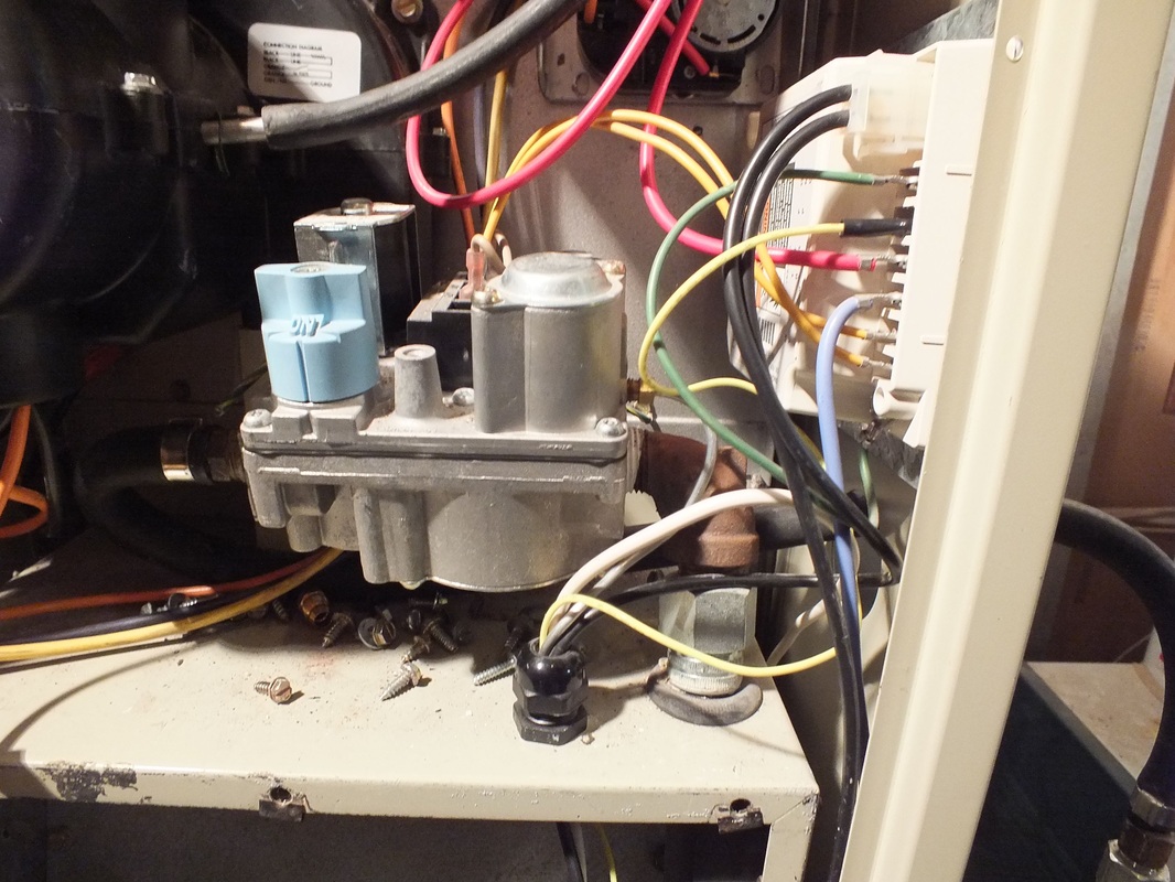
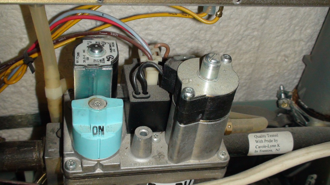
Gas valves are the devices that HVAC manufacturers and installation experts use to ensure safety and security in residential, or commercial settings. Gas valves help to control the flow of gas within a system, ensuring that everything runs according to plan. At Furnace Part Source, we find and stock the most reliable gas valves, from the best brands around the country, to give you performance that you can trust.
Whether you’re looking for diaphragm gas valves that contain a valve and actuator in a single body, or you need a solution in the form of combustion gas valves, you can find everything you’re looking for here at Furnace Part Source. We provide burner tubes, furnace gas valves, main burner assembly parts, slow open kits, and more. Our parts can handle gas in boilers, commercial water heaters, and heating systems. For that reason, we recommend that you peruse the various options for repair and replacement.
As any expert knows, an HVAC specialist can only build a great heating system with the best possible parts. At Furnace Part Source, we combine exceptional customer service with great prices and quick delivery, to give you the ultimate HVAC solution.
Standard solenoid valves are used for pneumatic gases; testing gas pressure at the valves is often the first thing HVAC technicians do when they are called in to check on faulty furnaces. Even though these systems are generally built to last, gas furnace valves are the parts more likely to need replacement over the life of the furnace.
For this reason, the Furnace Part Source keeps a wide assortment of valves to fit all major brands as well as systems that are not so common. Below are some of our most popular gas valves; they are offered at wholesale prices and are ready to ship on the spot.
This valve is for natural gas Carrier furnaces. It is a factory authorized part that includes the manifold and all other pieces needed for complete replacement.
Honeywell gas valves represent the brand’s dedication to quality. This universal part will fit various Honeywell gas appliances. In the case of Honeywell 24 Vac furnaces, it can handle either natural or liquefied petroleum gas when the adequate conversion kit is used. The current version of this gas valve features a compact design with a rotation radius of about four inches, thus making it easy to reposition as needed even in the tightest spaces.
Popular Emerson furnaces feature HSI and DSI electronic ignition systems. The 36J22-214 Emerson gas valve provides a one-stage fast opening system that fits into a very compact part for half-inch pipes. This is a straight-flow valve that includes a conversion kit for LP gas.
The Selectra line of modulator gas valves from Maxitrol feature unique systems for quick temperature control without the need of an actuating motor or butterfly valve. The M411 gas valve will fit half-inch and 3/8″ pipes. Both direct and indirect gas-fired appliances can be regulated with Selectra gas valves.
You need to know the signs of when your gas valve is failing. The first is if the valve is receiving an allotted number of volts to open or close — 24 is the standard –and you hear no internal clicking. That’s a sign that it may not be opening or closing.
Use an electronic gas sniffer to detect leaks. Leaks can be dangerous with the gas’s combustion properties. Assess pressure levels as well to see if the valve may not be working due to improper settings. Unclog your burner orifices and ductwork, since a lack of flow can also be the culprit.
If you have conducted all of these steps and the gas valve is still not working, then replace the valves. Never bang them with any tools to open them because that can risk an explosion.
When it comes to finding the right parts and equipment for your HVAC equipment needs, you can trust Furnace Part Source’s extensive catalog. Active since 2006, the catalog has more than 500,000 items offered at wholesale prices. You will find exactly what you need to replace control valves and prevent imminent shutoffs.

Searching for tools to control the flow of your piping system? Explore one of the largest featured collections of products and discover a range of wholesale boiler safety valve on Alibaba.com. When you search for boiler safety valve and related items, you will be able to find many types of boiler safety valve varying in size, shape, use, and quality, all at prices in which are highly reasonable!
There are many uses of valves - mainly controlling the flow of fluids and pressure. Some examples include regulating water for irrigation, industrial uses for controlling processes, and residential piping systems. Magnetic valves like those using the solenoid, are often used in a range of industrial processes. Whereas backflow preventers are often used in residential and commercial buildings to ensure the safety and hygiene of the water supplies. Whether you are designing a regulation system for irrigation or merely looking for a new replacement, you will be able to find whatever type of boiler safety valve that you need. Our products vary from check valves to pressure reducing valves, ball valves, butterfly valves, thermostatic mixing valves, and a lot more.
Control Southern Mechanical Services is fully certified by the National Board of Boiler & Pressure Vessel Inspections and is authorized to apply “VR” stamps, and by The American Society of Mechanical Engineers to certify section I - “V”, and Section 8 - “UV” valves.
Taylor Valve Technology® is a manufacturer leader in high-quality industrial valves. We deliver safety relief, high-pressure relief, and back pressure relief valves. Our wide array of choke and control valves and pilot-operated valve products are second to none. Products are designed for demanding industrial needs, meeting quality API and ASME Code requirements. High-demand oil & gas industry, chemical plants, power generators, and the processing industry depend on our valves for consistency and durability. Get effective flow control of liquid, steam, and gas. Valves ship from the Taylor Valve Technology, Inc. United States facility. Delivering worldwide, you can depend on quick turnaround times.


 8613371530291