
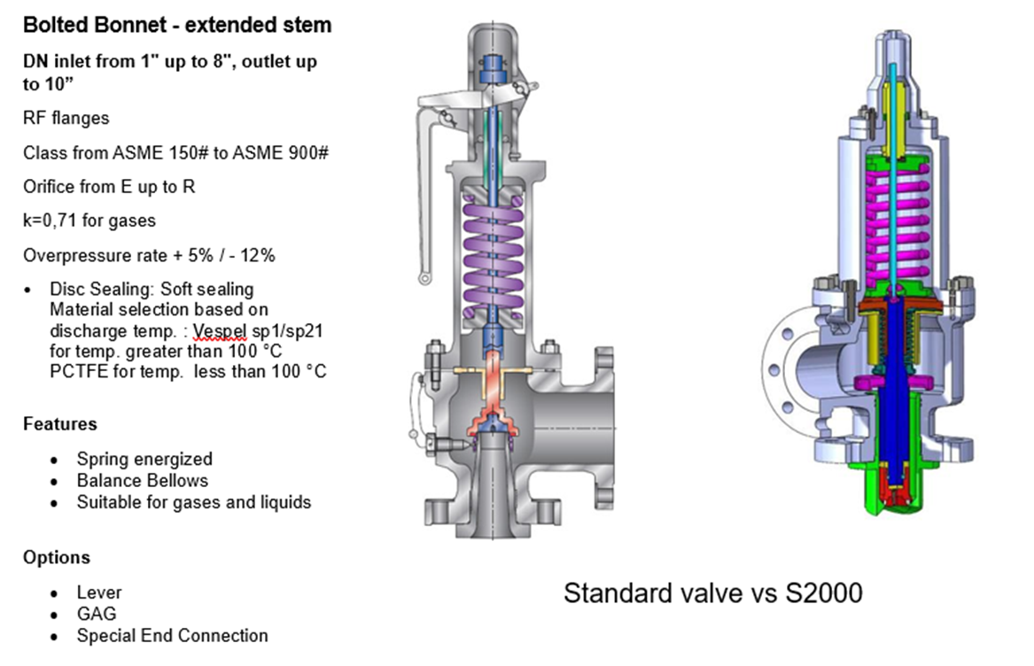
gag safety valve factory

IMO your question is more suitable for PSV forum http://www.eng-tips.com/threadminder.cfm?pid=1203 . Of course some of us in this forum have experiences in safety valve.
See some hint from some expert whom have done this http://www.eng-tips.com/viewthread.cfm?qid=180240 . Moral of the story, this is a risky job with some uncertainties, be cautious for operator to position themselves when performing this. If your safety valve is open loop, do not position any parts of someones" body in front or near the outlet
For gaging as well as adjusting it in relatively safe manner, Trevi-test is one way to do it. similar video by Tru-test https://www.youtube.com/watch?v=gAwS-tjbLeg
Be cautious that you or the commissioning personnel should correspond both safety valves" setting pressure vs the testing pressure. If its gagged (set the screw to prevent it from opening)at X Psi, then the testing pressure is not advisable to exceed 5% of X. this potentially bent the spindle. And if this happened, as per safety regulation the damage parts shall be renewed with UV stamped (read: original) manufacturer parts (if your safety valve manufacturer and your boiler are referring to ASME).

There is a wide range of safety valves available to meet the many different applications and performance criteria demanded by different industries. Furthermore, national standards define many varying types of safety valve.
The ASME standard I and ASME standard VIII for boiler and pressure vessel applications and the ASME/ANSI PTC 25.3 standard for safety valves and relief valves provide the following definition. These standards set performance characteristics as well as defining the different types of safety valves that are used:
ASME I valve - A safety relief valve conforming to the requirements of Section I of the ASME pressure vessel code for boiler applications which will open within 3% overpressure and close within 4%. It will usually feature two blowdown rings, and is identified by a National Board ‘V’ stamp.
ASME VIII valve- A safety relief valve conforming to the requirements of Section VIII of the ASME pressure vessel code for pressure vessel applications which will open within 10% overpressure and close within 7%. Identified by a National Board ‘UV’ stamp.
Full bore safety valve - A safety valve having no protrusions in the bore, and wherein the valve lifts to an extent sufficient for the minimum area at any section, at or below the seat, to become the controlling orifice.
Conventional safety relief valve -The spring housing is vented to the discharge side, hence operational characteristics are directly affected by changes in the backpressure to the valve.
Balanced safety relief valve -A balanced valve incorporates a means of minimising the effect of backpressure on the operational characteristics of the valve.
Pilot operated pressure relief valve -The major relieving device is combined with, and is controlled by, a self-actuated auxiliary pressure relief device.
Power-actuated safety relief valve - A pressure relief valve in which the major pressure relieving device is combined with, and controlled by, a device requiring an external source of energy.
Standard safety valve - A valve which, following opening, reaches the degree of lift necessary for the mass flowrate to be discharged within a pressure rise of not more than 10%. (The valve is characterised by a pop type action and is sometimes known as high lift).
Full lift (Vollhub) safety valve -A safety valve which, after commencement of lift, opens rapidly within a 5% pressure rise up to the full lift as limited by the design. The amount of lift up to the rapid opening (proportional range) shall not be more than 20%.
Direct loaded safety valve -A safety valve in which the opening force underneath the valve disc is opposed by a closing force such as a spring or a weight.
Proportional safety valve - A safety valve which opens more or less steadily in relation to the increase in pressure. Sudden opening within a 10% lift range will not occur without pressure increase. Following opening within a pressure of not more than 10%, these safety valves achieve the lift necessary for the mass flow to be discharged.
Diaphragm safety valve -A direct loaded safety valve wherein linear moving and rotating elements and springs are protected against the effects of the fluid by a diaphragm
Bellows safety valve - A direct loaded safety valve wherein sliding and (partially or fully) rotating elements and springs are protected against the effects of the fluids by a bellows. The bellows may be of such a design that it compensates for influences of backpressure.
Controlled safety valve - Consists of a main valve and a control device. It also includes direct acting safety valves with supplementary loading in which, until the set pressure is reached, an additional force increases the closing force.
Safety valve - A safety valve which automatically, without the assistance of any energy other than that of the fluid concerned, discharges a quantity of the fluid so as to prevent a predetermined safe pressure being exceeded, and which is designed to re-close and prevent further flow of fluid after normal pressure conditions of service have been restored. Note; the valve can be characterised either by pop action (rapid opening) or by opening in proportion (not necessarily linear) to the increase in pressure over the set pressure.
Direct loaded safety valve -A safety valve in which the loading due to the fluid pressure underneath the valve disc is opposed only by a direct mechanical loading device such as a weight, lever and weight, or a spring.
Assisted safety valve -A safety valve which by means of a powered assistance mechanism, may additionally be lifted at a pressure lower than the set pressure and will, even in the event of a failure of the assistance mechanism, comply with all the requirements for safety valves given in the standard.
Supplementary loaded safety valve - A safety valve that has, until the pressure at the inlet to the safety valve reaches the set pressure, an additional force, which increases the sealing force.
Note; this additional force (supplementary load), which may be provided by means of an extraneous power source, is reliably released when the pressure at the inlet of the safety valve reaches the set pressure. The amount of supplementary loading is so arranged that if such supplementary loading is not released, the safety valve will attain its certified discharge capacity at a pressure not greater than 1.1 times the maximum allowable pressure of the equipment to be protected.
Pilot operated safety valve -A safety valve, the operation of which is initiated and controlled by the fluid discharged from a pilot valve, which is itself, a direct loaded safety valve subject to the requirement of the standard.
The common characteristic shared between the definitions of conventional safety valves in the different standards, is that their operational characteristics are affected by any backpressure in the discharge system. It is important to note that the total backpressure is generated from two components; superimposed backpressure and the built-up backpressure:
Subsequently, in a conventional safety valve, only the superimposed backpressure will affect the opening characteristic and set value, but the combined backpressure will alter the blowdown characteristic and re-seat value.
The ASME/ANSI standard makes the further classification that conventional valves have a spring housing that is vented to the discharge side of the valve. If the spring housing is vented to the atmosphere, any superimposed backpressure will still affect the operational characteristics. Thiscan be seen from Figure 9.2.1, which shows schematic diagrams of valves whose spring housings are vented to the discharge side of the valve and to the atmosphere.
By considering the forces acting on the disc (with area AD), it can be seen that the required opening force (equivalent to the product of inlet pressure (PV) and the nozzle area (AN)) is the sum of the spring force (FS) and the force due to the backpressure (PB) acting on the top and bottom of the disc. In the case of a spring housing vented to the discharge side of the valve (an ASME conventional safety relief valve, see Figure 9.2.1 (a)), the required opening force is:
In both cases, if a significant superimposed backpressure exists, its effects on the set pressure need to be considered when designing a safety valve system.
Once the valve starts to open, the effects of built-up backpressure also have to be taken into account. For a conventional safety valve with the spring housing vented to the discharge side of the valve, see Figure 9.2.1 (a), the effect of built-up backpressure can be determined by considering Equation 9.2.1 and by noting that once the valve starts to open, the inlet pressure is the sum of the set pressure, PS, and the overpressure, PO.
Balanced safety valves are those that incorporate a means of eliminating the effects of backpressure. There are two basic designs that can be used to achieve this:
Although there are several variations of the piston valve, they generally consist of a piston type disc whose movement is constrained by a vented guide. The area of the top face of the piston, AP, and the nozzle seat area, AN, are designed to be equal. This means that the effective area of both the top and bottom surfaces of the disc exposed to the backpressure are equal, and therefore any additional forces are balanced. In addition, the spring bonnet is vented such that the top face of the piston is subjected to atmospheric pressure, as shown in Figure 9.2.2.
The bellows arrangement prevents backpressure acting on the upper side of the disc within the area of the bellows. The disc area extending beyond the bellows and the opposing disc area are equal, and so the forces acting on the disc are balanced, and the backpressure has little effect on the valve opening pressure.
Bellows failure is an important concern when using a bellows balanced safety valve, as this may affect the set pressure and capacity of the valve. It is important, therefore, that there is some mechanism for detecting any uncharacteristic fluid flow through the bellows vents. In addition, some bellows balanced safety valves include an auxiliary piston that is used to overcome the effects of backpressure in the case of bellows failure. This type of safety valve is usually only used on critical applications in the oil and petrochemical industries.
Since balanced pressure relief valves are typically more expensive than their unbalanced counterparts, they are commonly only used where high pressure manifolds are unavoidable, or in critical applications where a very precise set pressure or blowdown is required.
This type of safety valve uses the flowing medium itself, through a pilot valve, to apply the closing force on the safety valve disc. The pilot valve is itself a small safety valve.
The diaphragm type is typically only available for low pressure applications and it produces a proportional type action, characteristic of relief valves used in liquid systems. They are therefore of little use in steam systems, consequently, they will not be considered in this text.
The piston type valve consists of a main valve, which uses a piston shaped closing device (or obturator), and an external pilot valve. Figure 9.2.4 shows a diagram of a typical piston type, pilot operated safety valve.
The piston and seating arrangement incorporated in the main valve is designed so that the bottom area of the piston, exposed to the inlet fluid, is less than the area of the top of the piston. As both ends of the piston are exposed to the fluid at the same pressure, this means that under normal system operating conditions, the closing force, resulting from the larger top area, is greater than the inlet force. The resultant downward force therefore holds the piston firmly on its seat.
If the inlet pressure were to rise, the net closing force on the piston also increases, ensuring that a tight shut-off is continually maintained. However, when the inlet pressure reaches the set pressure, the pilot valve will pop open to release the fluid pressure above the piston. With much less fluid pressure acting on the upper surface of the piston, the inlet pressure generates a net upwards force and the piston will leave its seat. This causes the main valve to pop open, allowing the process fluid to be discharged.
When the inlet pressure has been sufficiently reduced, the pilot valve will reclose, preventing the further release of fluid from the top of the piston, thereby re-establishing the net downward force, and causing the piston to reseat.
Pilot operated safety valves offer good overpressure and blowdown performance (a blowdown of 2% is attainable). For this reason, they are used where a narrow margin is required between the set pressure and the system operating pressure. Pilot operated valves are also available in much larger sizes, making them the preferred type of safety valve for larger capacities.
One of the main concerns with pilot operated safety valves is that the small bore, pilot connecting pipes are susceptible to blockage by foreign matter, or due to the collection of condensate in these pipes. This can lead to the failure of the valve, either in the open or closed position, depending on where the blockage occurs.
The terms full lift, high lift and low lift refer to the amount of travel the disc undergoes as it moves from its closed position to the position required to produce the certified discharge capacity, and how this affects the discharge capacity of the valve.
A full lift safety valve is one in which the disc lifts sufficiently, so that the curtain area no longer influences the discharge area. The discharge area, and therefore the capacity of the valve are subsequently determined by the bore area. This occurs when the disc lifts a distance of at least a quarter of the bore diameter. A full lift conventional safety valve is often the best choice for general steam applications.
The disc of a high lift safety valve lifts a distance of at least 1/12th of the bore diameter. This means that the curtain area, and ultimately the position of the disc, determines the discharge area. The discharge capacities of high lift valves tend to be significantly lower than those of full lift valves, and for a given discharge capacity, it is usually possible to select a full lift valve that has a nominal size several times smaller than a corresponding high lift valve, which usually incurs cost advantages.Furthermore, high lift valves tend to be used on compressible fluids where their action is more proportional.
In low lift valves, the disc only lifts a distance of 1/24th of the bore diameter. The discharge area is determined entirely by the position of the disc, and since the disc only lifts a small amount, the capacities tend to be much lower than those of full or high lift valves.
Except when safety valves are discharging, the only parts that are wetted by the process fluid are the inlet tract (nozzle) and the disc. Since safety valves operate infrequently under normal conditions, all other components can be manufactured from standard materials for most applications. There are however several exceptions, in which case, special materials have to be used, these include:
Cast steel -Commonly used on higher pressure valves (up to 40 bar g). Process type valves are usually made from a cast steel body with an austenitic full nozzle type construction.
For all safety valves, it is important that moving parts, particularly the spindle and guides are made from materials that will not easily degrade or corrode. As seats and discs are constantly in contact with the process fluid, they must be able to resist the effects of erosion and corrosion.
The spring is a critical element of the safety valve and must provide reliable performance within the required parameters. Standard safety valves will typically use carbon steel for moderate temperatures. Tungsten steel is used for higher temperature, non-corrosive applications, and stainless steel is used for corrosive or clean steam duty. For sour gas and high temperature applications, often special materials such as monel, hastelloy and ‘inconel’ are used.
Standard safety valves are generally fitted with an easing lever, which enables the valve to be lifted manually in order to ensure that it is operational at pressures in excess of 75% of set pressure. This is usually done as part of routine safety checks, or during maintenance to prevent seizing. The fitting of a lever is usually a requirement of national standards and insurance companies for steam and hot water applications. For example, the ASME Boiler and Pressure Vessel Code states that pressure relief valves must be fitted with a lever if they are to be used on air, water over 60°C, and steam.
A test gag (Figure 9.2.7) may be used to prevent the valve from opening at the set pressure during hydraulic testing when commissioning a system. Once tested, the gag screw is removed and replaced with a short blanking plug before the valve is placed in service.
The amount of fluid depends on the particular design of safety valve. If emission of this fluid into the atmosphere is acceptable, the spring housing may be vented to the atmosphere – an open bonnet. This is usually advantageous when the safety valve is used on high temperature fluids or for boiler applications as, otherwise, high temperatures can relax the spring, altering the set pressure of the valve. However, using an open bonnet exposes the valve spring and internals to environmental conditions, which can lead to damage and corrosion of the spring.
When the fluid must be completely contained by the safety valve (and the discharge system), it is necessary to use a closed bonnet, which is not vented to the atmosphere. This type of spring enclosure is almost universally used for small screwed valves and, it is becoming increasingly common on many valve ranges since, particularly on steam, discharge of the fluid could be hazardous to personnel.
Some safety valves, most commonly those used for water applications, incorporate a flexible diaphragm or bellows to isolate the safety valve spring and upper chamber from the process fluid, (see Figure 9.2.9).
Test Gag is a bolt used for the spindle block of the pressure relief valve (PRV) to allow the PRV to be closed during the pressure test. The bolt should be tightened when the system has 80% of the pressure used. test (test pressure) to ensure that the PRV is closed at the test Pressure:
A safety valve can be considered as a pressure reducing or pressure removing device. When there is any excessive internal fluid pressure then this valve would open so that the damage in the system can be prevented. These valves are commonly used in gas and steam lines. In an unprotected pressure vessel or a system if the pressure level exceeds the safe pressure level, then there could be catastrophic effects on both plant and personnel. The major purpose of a safety relief valve is to protect any pressurized system from the effects of exceeding its design pressure limit. These valves are designed to automatically discharge gas pressure or liquid from any pressure-containing system and thus it prevents excessive pressure and protects plants and personnel. In order to fulfill all this, a safety valve should be properly sized, selected, installed, and maintained.
A relief valve would release the liquid or open the valve in a proportional manner so that it can maintain some system pressure. In the case of a safety valve, it would quickly lift and reduce the pressure instantly. The major difference is in the capacity and set point. The relief valve would relieve pressure in case of overpressure conditions, it has an operator that would give a control signal to open the valve. Safety valves operate without the help of an operator. The relief valve would open gradually as the fluid pressure increases while the safety valve opens fully when the set pressure is reached. The safety valve will open fully if the system achieves the opening pressure and there is no half or semi-open position for a safety valve like the relief valve.
Safety relief valves are widely used in most of the process equipment. These valves can be used as either a relief valve or a safety valve. These valves can be used in gas and vapor system as safety valves and they can also be used as a relief valve in a liquid system.
Nozzle– Nozzle is the entrance by which the process fluid enters into the valve. There are many types of nozzles available they are fully threaded and removable, semi threaded and removable, semi, welded in the valve body, semi pressed and removable.
The internal components of safety valves such as spindle or guides which is the moving part must be constructed by using materials that will not easily corrode. The seats and discs must be able to resist corrosion, so stainless steel is used for their construction. Sometimes nozzle discs are constructed by using special alloys such as Hastelloy or monel.
If the pressure rises above the set pressure in a system, the disc will begin to lift off its seat. The spring will start to compress and the spring force also increases. So the lift will happen only if the pressure is increased again and after that, the flow through the valve occurs. Overpressure is the additional pressure rise needed before the safety valve will discharge at its rated capacity. Overpressure is dependent upon the set pressure and the standard for the particular application. The disc in the safety valve is arranged in a way that a slight increase in pressure than the set pressure could cause the valve to open. When the pressure reaches a safe level in the system the valve would return to its closed position. The disc is arranged for rapid opening in order to achieve this most safety valves have a secondary chamber formed by a shroud, skirt, or hood around the outside diameter of the disc.
This type of valve, it has a spring housing that is vented to the discharge side of the valve. The operational characteristic of the valve is affected by the changes in the backpressure of the valve. This is the simplest type of safety valve and they are used in the backpressure and are very small.
Balanced safety valves are capable to remove back pressure effects with the help of bellows or other equipment. These valves are spring-loaded safety relief valves, these valves are installed when the percentage build-up back pressure in the exhaust system is allowed to exceed the percentage overpressure applicable to the safety valve. Balanced safety valves are of two types, piston type, and bellow type.
A pilot-operated safety valve is a pressure relief valve, in which the major relieving device is with a self-actuated auxiliary relief valve. The relieving device is controlled by the auxiliary relief valve. Pilot operated safety valves are of two types they are diaphragm and piston type. The diaphragm type is used for low-pressure applications. In the case of the piston-type valve, it has a main valve that uses a piston-shaped closing device and an external pilot valve.
In this type, the nozzle is formed from the base of the valve, mostly these valves have a screwed connection but they are also available in flanged or weld-ended and these valves would fully open at twenty-five percent overpressure and they have closed bonnet.
This valve is a pressure switch initiated safety valve and it is set to lift on a particular pressure but a regular safety valve will only lift after the accumulation of pressure.
During the plant commissioning procedure, the valve would be lifted and there would be seat damage if there is debris or dirt. So the system should be flushed out before installing a safety valve if done so foreign matter won’t pass through the valve. The valve must be installed in a place where dirt and debris must not collect. The safety valve should be mounted vertically in a pressure vessel. The pressure drop in the valve inlet piping must not exceed more than three percent of the set pressure. In steam applications, the safety valve must be installed above the steam pipe. It should not be installed below because, the steam will condense, fill the pipe, and wets the upstream side of the safety valve seat.
The system operating pressure must not be too close to the valve set pressure. A safety valve needs a five to ten percent difference between the operating and set pressure. Safety valves must not be set to less than 15PSI. It should be in the range of 20-25 according to the pressure that the vessels could handle. We must not install safety valves horizontally safety valves are meant to work only in a vertical position, if not it won’t work properly. Safety valves must be stored in a dry environment and protected from weather, they should not be removed from the skids or crates until immediately prior to installation. The valve must be kept in a way that the inlet is down so that damage can be prevented. Safety valves must be subjected to an annual periodic inspection. If the safety valves are installed outdoor then they would be exposed to wind, air, snow, dirt, so certain safety features must be done. The inlet neck of the safety valve and the valve body must be insulated and the exterior part of the insulation must be weatherproof. Certain spares must be needed for the safety valve they are flat lapping plate, high-temperature lubricant, a lapping compound of grit size.
Leakage can happen if there is dirt or scale sitting on the seating surface. Lifting of the lever can remove the dirt. Mostly the leakage can be caused after the initial manufacture and test, this problem occurs from the damage during transit. If the installation is not proper it can cause valve leakage. Teflon coat or pipe dope can cause valve leakage. So it must be checked when the valve is installed we must ensure that it is not too low on threads if this gets into the valve it can stick on the seating surface and can cause a leak.

In the United States, use of such devices was spurred by the 1,700 boiler explosions that resulted in 1,300 deaths from 1905 to 1911. By 1915, the American Society of Mechanical Engineers (ASME) published its first boiler code, Rules for Construction of Stationary Boilers and Allowable Working Pressures, incorporating rules for construction and installation of safety valves for boilers.
The primary purpose of a pressure relief valve is to open to relieve excess pressure, reclose and prevent further flow of fluid after normal conditions have been restored (Figure 5). A secondary purpose is to minimize damage to other system components through operation of the pressure relief valve itself. A pressure relief valve designed under ASME Boiler and Pressure Vessel Code is stamped with the certification mark, and one of the certification designators: V, NV, HV, UV, UV3 or TV.
The many types of pressure relief valves that exist are based on different designs and construction. Generally, they’re classified as: safety relief valves, relief valves and safety valves.
A conventional safety relief valve is a spring-loaded pressure relief valve characterized by a rapid-opening pop action. Conventional safety relief valves are used for applications where excessive variable or built-up back pressure is not present in the system. The operational characteristics of these valves are directly affected by changes in the back pressure on the valve.
The working principle of a conventional spring-loaded safety relief valve is based on the balance of force. The spring load is preset to equal the force the inlet fluid exerts on the closed disk when the system pressure is at the set pressure of the valve.
The disk remains seated on the nozzle in the closed position when the inlet pressure is below the set pressure. The valve opens when the inlet pressure exceeds set pressure, overcoming the spring force. The valve recloses when the inlet pressure is reduced to a level below the set pressure.
Once the valve has opened, an additional pressure buildup at C occurs. This additional force at C causes the disk to lift substantially at pop. The valve closes when the inlet pressure has dropped sufficiently below the set pressure. The pressure at which the valve resets is called the closing pressure. The difference between the set pressure and closing pressure is the blowdown.
In the design of a conventional valve, an important consideration is seat leakage. This leakage can result in continuous loss of system fluid and may cause progressive damage to the valve seating surface. Based on the seating material, conventional valves are classified as:
Metal-seated valves. Metal-to-metal seats are commonly made from stainless or other hard alloy steels and are normally used for high-temperature applications such as steam and corrosive media applications for processing a wide variety of chemicals.
Soft-seated valve. An alternative to metal is resilient disks that can be fixed to either or both the seating surfaces where tighter shut-off is required. They are common for gas or liquid applications. These inserts may be made from a number of different materials, but Vinton, nitrile or EPDM (ethylene propylene diene monomer) are the most common.
Balanced bellows with auxiliary balancing piston. With this valve, the balanced bellows seal the body and fluid stream from the bonnet and working parts. The auxiliary balancing piston assures proper valve performance by compensating for back pressure in case the bellows fail.
The primary difference between a pilot-operated safety relief valve and a spring-loaded pressure relief valve is that the pilot-operated valve uses process pressure to keep the valve closed instead of a spring. A pilot is used to sense process pressure and to pressurize or vent the dome pressure chamber, which controls the valve opening or closing.
A pilot-operated safety relief valve consists of the main valve, a floating, unbalanced piston assembly, and an external pilot. The pilot controls the pressure on the top side of the main valve’s unbalanced moving chamber. A resilient seat is normally attached to the lower end.
At below-set level, the pressure on opposite sides of the moving member is equal. When the set pressure is reached, the pilot opens and depressurizes the cavity on the top side so the unbalanced member moves upward, causing the main valve to relieve. When the process pressure decreases to a predetermined pressure, the pilot closes, the cavity above the piston is depressurized and the main valve closes.
The valves operate bubble tight at higher operating pressure-to-set pressure ratios, allowing operators to run very close to the vessel’s maximum allowable working pressure.
Valve movement to open or close is fully controlled by a source of power such as electricity, steam or water (hydraulic). The valve may discharge to the atmosphere or to a container that is at lower pressure. The discharge capacity can be affected by downstream conditions.
Power-actuated safety relief valves are used mostly for forced-flow steam generators with no fixed steam or waterline. They are also used in nuclear power plants.
A temperature and pressure-actuated safety relief valve (also called a T&P safety relief valve) is a pressure relief valve that may be actuated by temperature or pressure on the inlet side (Figure 10).
Such a valve is designed for dual purposes. First, the T&P valve prevents temperature within a vessel from rising above a specified limit (generally 210°F or 98°C). Second, the T&P valve prevents pressure in the vessel from rising above a specified value.
A relief valve is actuated by inlet static pressure and a gradual lift that is generally proportional to the increase in pressure over opening pressure. Such a valve can be provided with enclosed spring housing suitable for closed discharge system applications.
Relief valves are commonly used in liquid systems, especially for lower capacities and thermal expansion applications. They also can be used on pump systems.
Adjustable relief valves feature convenient adjustment of the pressure setting through the outlet port. They are suitable for non-vented or vented inline applications in chemical, petrochemical and high-purity gas industries.
Electronic relief valves (ERVs) are pilot-operated relief valves that offer zero leakage. The ERV package combines a zero-leakage isolation valve with electric controls to monitor and regulate system pressure. These valves provide protection either in a capacity-relieving function or simply in an overpressure-protection application.
Safety valves are typically used for boiler overpressure protection and other applications such as downstream from pressure-reducing controls. These valves are installed wherever the maximum allowable working pressure of boilers is likely to be exceeded. Safety valves are also used for compressible gases, in particular for steam and air.
Safety valves are classified according to the lift. The term “lift” refers to the amount of travel the valve undergoes as it moves from its closed position to the position required to produce the certified discharge capacity.
Low-lift are safety valves in which the valve lifts a distance of 1/24th of the bore diameter. Since the valve has a small lift, the capacity is much lower than other types.
High-lift are safety valves in which the valve lifts a distance of at least 1/12th of the bore diameter. High-lift valves are used on compressible fluids, where their action is more proportional.
Full-lift are safety valves for which the valve lifts a distance of at least 1/4th of the bore diameter. Full-lift valves are considered the best choice for general steam applications.
Test gags are used to hold the safety valve closed while equipment is subjected to a hydrostatic test. To avoid damage to the spindle and/or seat, care is required so the gag screw is not tightened.
Lifting mechanisms are used to open the pressure relief valves when the pressure under the valve disk is lower than the set pressure. These mechanisms are available in three basic types: plain lever, packaged lever and air-operated lifting devices.
A key advantage of selecting a butterfly valve is the reduction of space and weight to a system compared with other options such as ball, check, globe or gate valves.

If you don’t know your blow down from your pop action, NASVI has you covered. Here is a handy cheat sheet on safety valve lingo and how to accurately order them.
SAFETY RELIEF VALVE:Safety relief valves are basically like pop safety valves and are primarily for liquid service where the thermal expansion in a liquid-laden vessel actuates the valve. When vapor is generated in these vessels, due to uncontrolled heat input, this valve with the huddling chamber, will give a high disc lift and discharge the expanded vapors. This valve is also suitable for gas or vapor service.
SELECTION OF VALVE:Valves should be selected for the particular installation on which they are to be used and also on the basis of the rated discharge capacity. This should be equal to or greater than the maximum output of the system.
INSTALLATION:The valve is to be installed in a vertical position, into a clean fitting, using the proper size and type of wrench so as not to damage the valve. The discharge piping, without stop valves, shall be independently supported and sloped downward slightly to drain condensate.

(1) Boiler safety valves and safety relief valves must be as indicated in PG-67 through PG-73 of section I of the ASME Boiler and Pressure Vessel Code (incorporated by reference; see 46 CFR 52.01-1) except as noted otherwise in this section.
(3) On river steam vessels whose boilers are connected in batteries without means of isolating one boiler from another, each battery of boilers shall be treated as a single boiler and equipped with not less than two safety valves of equal size.
(4) (Modifies PG-70.) The total rated relieving capacity of drum and superheater safety valves as certified by the valve manufacturer shall not be less than the maximum generating capacity of the boiler which shall be determined and certified by the boiler manufacturer. This capacity shall be in compliance with PG-70 of section I of the ASME Boiler and Pressure Vessel Code.
(5) In the event the maximum steam generating capacity of the boiler is increased by any means, the relieving capacity of the safety valves shall be checked by an inspector, and, if determined to be necessary, valves of increased relieving capacity shall be installed.
(6) (Modifies PG-67.) Drum safety valves shall be set to relieve at a pressure not in excess of that allowed by the Certificate of Inspection. Where for any reason this is lower than the pressure for which the boiler was originally designed and the revised safety valve capacity cannot be recomputed and certified by the valve manufacturer, one of the tests described in PG-70(3) of section I of the ASME Boiler and Pressure Vessel Code shall be conducted in the presence of the Inspector to insure that the relieving capacity is sufficient at the lower pressure.
(8) Lever or weighted safety valves now installed may be continued in use and may be repaired, but when renewals are necessary, lever or weighted safety valves shall not be used. All such replacements shall conform to the requirements of this section.
(10) (Modifies PG-73.2.) Cast iron may be used only for caps and lifting bars. When used for these parts, the elongation must be at least 5 percent in 51mm (2 inch) gage length. Nonmetallic material may be used only for gaskets and packing.
(1) (Modifies PG-68.) Superheater safety valves shall be as indicated in PG-68 of section I of the ASME Boiler and Pressure Vessel Code except as noted otherwise in this paragraph.
(2) The setting of the superheater safety valve shall not exceed the design pressure of the superheater outlet flange or the main steam piping beyond the superheater. To prevent damage to the superheater, the drum safety valve shall be set at a pressure not less than that of the superheater safety valve setting plus 5 pounds minimum plus approximately the normal load pressure drop through the superheater and associated piping, including the controlled desuperheater if fitted. See also § 52.01-95(b) (1).
(3) Drum pilot actuated superheater safety valves are permitted provided the setting of the pilot valve and superheater safety valve is such that the superheater safety valve will open before the drum safety valve.
(1) (Modifies PG-71.) Safety valves shall be installed as indicated in PG-71 of section I of the ASME Boiler and Pressure Vessel Code except as noted otherwise in this paragraph.
(2) The final setting of boiler safety valves shall be checked and adjusted under steam pressure and, if possible, while the boiler is on the line and the steam is at operating temperatures, in the presence of and to the satisfaction of a marine inspector who, upon acceptance, shall seal the valves. This regulation applies to both drum and superheater safety valves of all boilers.
(3) The safety valve body drains required by PG-71 of section I of the ASME Boiler and Pressure Vessel Code shall be run as directly as possible from the body of each boiler safety valve, or the drain from each boiler safety valve may be led to an independent header common only to boiler safety valve drains. No valves of any type shall be installed in the leakoff from drains or drain headers and they shall be led to suitable locations to avoid hazard to personnel.
(1) (Modifies PG-72.) The operation of safety valves shall be as indicated in PG-72 of section I of the ASME Boiler and Pressure Vessel Code except as noted in paragraph (d)(2) of this section.


 8613371530291