
gas boiler safety valve free sample

Boiler explosions have been responsible for widespread damage to companies throughout the years, and that’s why today’s boilers are equipped with safety valves and/or relief valves. Boiler safety valves are designed to prevent excess pressure, which is usually responsible for those devastating explosions. That said, to ensure that boiler safety valves are working properly and providing adequate protection, they must meet regulatory specifications and require ongoing maintenance and periodic testing. Without these precautions, malfunctioning safety valves may fail, resulting in potentially disastrous consequences.
Boiler safety valves are activated by upstream pressure. If the pressure exceeds a defined threshold, the valve activates and automatically releases pressure. Typically used for gas or vapor service, boiler safety valves pop fully open once a pressure threshold is reached and remain open until the boiler pressure reaches a pre-defined, safe lower pressure.
Boiler relief valves serve the same purpose – automatically lowering boiler pressure – but they function a bit differently than safety valves. A relief valve doesn’t open fully when pressure exceeds a defined threshold; instead, it opens gradually when the pressure threshold is exceeded and closes gradually until the lower, safe threshold is reached. Boiler relief valves are typically used for liquid service.
There are also devices known as “safety relief valves” which have the characteristics of both types discussed above. Safety relief valves can be used for either liquid or gas or vapor service.
Nameplates must be fastened securely and permanently to the safety valve and remain readable throughout the lifespan of the valve, so durability is key.
The National Board of Boiler and Pressure Vessel Inspectors offers guidance and recommendations on boiler and pressure vessel safety rules and regulations. However, most individual states set forth their own rules and regulations, and while they may be similar across states, it’s important to ensure that your boiler safety valves meet all state and local regulatory requirements.
The National Board published NB-131, Recommended Boiler and Pressure Vessel Safety Legislation, and NB-132, Recommended Administrative Boiler and Pressure Vessel Safety Rules and Regulationsin order to provide guidance and encourage the development of crucial safety laws in jurisdictions that currently have no laws in place for the “proper construction, installation, inspection, operation, maintenance, alterations, and repairs” necessary to protect workers and the public from dangerous boiler and pressure vessel explosions that may occur without these safeguards in place.
The American Society of Mechanical Engineers (ASME) governs the code that establishes guidelines and requirements for safety valves. Note that it’s up to plant personnel to familiarize themselves with the requirements and understand which parts of the code apply to specific parts of the plant’s steam systems.
High steam capacity requirements, physical or economic constraints may make the use of a single safety valve impossible. In these cases, using multiple safety valves on the same system is considered an acceptable practice, provided that proper sizing and installation requirements are met – including an appropriately sized vent pipe that accounts for the total steam venting capacity of all valves when open at the same time.
The lowest rating (MAWP or maximum allowable working pressure) should always be used among all safety devices within a system, including boilers, pressure vessels, and equipment piping systems, to determine the safety valve set pressure.
Avoid isolating safety valves from the system, such as by installing intervening shut-off valves located between the steam component or system and the inlet.
Contact the valve supplier immediately for any safety valve with a broken wire seal, as this indicates that the valve is unsafe for use. Safety valves are sealed and certified in order to prevent tampering that can prevent proper function.
Avoid attaching vent discharge piping directly to a safety valve, which may place unnecessary weight and additional stress on the valve, altering the set pressure.

A boiler valve kit is a must-have for any homeowner with a boiler system. This brass valve kit features a vent safety valve that helps to protect your home from dangerous gas build-up. The included instructions make installation easy, and the durable brass construction ensures lasting performance. Keep your family safe with this essential boiler valve kit.
9. When the calibrated pressure is reached, the valve opens automatically and discharges the atmosphere to protect the whole system from safe caused by overpressure
10. This brass boiler valve kit is perfect for any steam-powered project. The kit includes a pressure gauge, safety valve, and two shut-off valves. The pressure gauge helps you monitor the pressure in your boiler, the safety valve keeps your boiler from exploding, and the shut-off valves let you turn off the steam supply without having to drain the boiler.
This brass boiler valve kit is perfect for any steam-related projects you may have. It includes a durable boiler and vent safety valve to keep your project safe and functional. The included instructions make it easy to install this kit in no time. This boiler valve kit is the perfect addition to your tool collection with its high-quality construction and affordable price. This brass boiler valve kit is ideal for any steam-based appliance. The kit includes a boiler valve, vent safety valve, and all the necessary fittings for a quick and easy installation. The included vent safety valve helps to ensure safe operation by releasing excess pressure in the event of a malfunction. This kit is ideal for use with any boiler, including cast iron, steel, or copper boilers.
Vent safety valves are required for all direct-fired appliances; this kit includes everything you need to install one. The boiler valve is brass and has a 1/2-inch pipe thread fitting that can be connected to the vent pipe. It also features an adjustable pressure relief valve with a gauge, protecting your home from high-pressure steam or air from the system. This kit comes with two elbows (1 in., two in.), four nipples (3/4 in., 1/8 in., 3/8 in.), three straight fittings (5/16 inches), and five pipe connectors (3 ways).
This boiler kit includes a brass pressure relief valve with an air vent, which is required by law. It also has a 1/2″ discharge elbow and two unions connecting the pipe inlet to your water heater. The safety valves are designed to prevent excess pressure from building up inside the tank, which can cause dangerous boil-overs or even potential explosions. This kit is excellent for homeowners with existing water heaters without this equipment installed.

As is the case with most projects, the mechanical rooms are too small to allow for a simple installation of the required equipment, the chases are too small for the items that must pass through them, etc., etc. When managing construction projects, many of you probably feel as though you spend the majority of your time working to find creative ways to effectively minimize labor overages, while at the same time squeezing 10 pounds of beans into a 5 pound bag….on an already tight labor budget. While we cannot magically increase the size of the mechanical room for you or clone your top field personnel with this article, the following information will provide you with some options that will simplify your next boiler project.
I believe that on almost every boiler project that I have been involved in over the past few decades, there always seems to be confusion regarding the venting requirements for safety relief valves and gas regulator common venting. Below, I have referenced the codes that apply to these topics, in addition to some examples.
Where there is more than one gas pressure regulator at a location, each gas pressure regulator shall have a separate vent to the outdoors at a safe point of discharge as determined by the authority having jurisdiction. If approved by the authority having jurisdiction, the vent lines may be manifolded in accordance with accepted engineering practices [see (b) and (c) below] to minimize backpressure in the event of diaphragm failure. (b) Atmospheric vent lines, when manifolded shall be connected to a common atmospheric vent line having a cross sectional area not less than the area of the largest vent line plus 50% of the area of the additional vent lines. (c) Atmospheric vent lines shall not be connected to any common manifolded gas vent, bleed or relief lines.
(C) It is recommended that individual discharge lines be used, but if two or more reliefs are combined, the discharge piping shall be designed with sufficient flow area to prevent blowout of steam or other fluids. Sectional areas of a discharge pipe shall not be less than the full area of the valve outlets discharging thereinto and the discharge pipe shall be as short and straight as possible and so arranged as to avoid undue stresses on the valve or valves.
After reviewing the codes detailed above, you can see that contrary to popular belief, it is possible to incorporate a common vent manifold for boiler safety relief valves, and also for gas valves. Below are some examples.
Manifold gas vent lines common (1 ¼” each boiler x (4) Units (1.84” + .92” +.92” + .92” = 4.6”) therefore, a 2 ½” manifold would be recommended (cross sectional area of 4.9”)
Manifolded relief valves (I don’t interpret this code to limit only the boilers to this vent line but would include DA and pressure reducing stations)
Boilers (2) 2 ½” relief valves per boiler (4.9” cross sectional area each) x (4) Boilers (39.2” total) therefore, an 8” manifold would be recommended (50.2” cross sectional area).
The same methodology can be used when venting pressure reducing stations and deaerators per the referenced code with proper Department approval. Remember, the purpose of a Drip Pan Elbow is to provide a suitable unrestricted, self-draining outlet in addition to isolating Safety Relief Valves (SRV’s) from discharge piping stresses. The Safety Relief Valve discharge size increases to isolate the drip pan elbow from backpressure. Steam won’t escape from the drip pan elbow if the vent line is sized appropriately.
If you run into a situation where common venting is required for safety relief valve(s), gas regulators, or pressure reducing stations, please feel free to contact Fluid Handling, Inc. in Menomonee Falls, WI and we will work with you to determine the appropriate solution.
In order to ensure that the maximum allowable accumulation pressure of any system or apparatus protected by a safety valve is never exceeded, careful consideration of the safety valve’s position in the system has to be made. As there is such a wide range of applications, there is no absolute rule as to where the valve should be positioned and therefore, every application needs to be treated separately.
A common steam application for a safety valve is to protect process equipment supplied from a pressure reducing station. Two possible arrangements are shown in Figure 9.3.3.
The safety valve can be fitted within the pressure reducing station itself, that is, before the downstream stop valve, as in Figure 9.3.3 (a), or further downstream, nearer the apparatus as in Figure 9.3.3 (b). Fitting the safety valve before the downstream stop valve has the following advantages:
• The safety valve can be tested in-line by shutting down the downstream stop valve without the chance of downstream apparatus being over pressurised, should the safety valve fail under test.
• When setting the PRV under no-load conditions, the operation of the safety valve can be observed, as this condition is most likely to cause ‘simmer’. If this should occur, the PRV pressure can be adjusted to below the safety valve reseat pressure.
Indeed, a separate safety valve may have to be fitted on the inlet to each downstream piece of apparatus, when the PRV supplies several such pieces of apparatus.
• If supplying one piece of apparatus, which has a MAWP pressure less than the PRV supply pressure, the apparatus must be fitted with a safety valve, preferably close-coupled to its steam inlet connection.
• If a PRV is supplying more than one apparatus and the MAWP of any item is less than the PRV supply pressure, either the PRV station must be fitted with a safety valve set at the lowest possible MAWP of the connected apparatus, or each item of affected apparatus must be fitted with a safety valve.
• The safety valve must be located so that the pressure cannot accumulate in the apparatus viaanother route, for example, from a separate steam line or a bypass line.
It could be argued that every installation deserves special consideration when it comes to safety, but the following applications and situations are a little unusual and worth considering:
• Fire - Any pressure vessel should be protected from overpressure in the event of fire. Although a safety valve mounted for operational protection may also offer protection under fire conditions,such cases require special consideration, which is beyond the scope of this text.
• Exothermic applications - These must be fitted with a safety valve close-coupled to the apparatus steam inlet or the body direct. No alternative applies.
• Safety valves used as warning devices - Sometimes, safety valves are fitted to systems as warning devices. They are not required to relieve fault loads but to warn of pressures increasing above normal working pressures for operational reasons only. In these instances, safety valves are set at the warning pressure and only need to be of minimum size. If there is any danger of systems fitted with such a safety valve exceeding their maximum allowable working pressure, they must be protected by additional safety valves in the usual way.
In order to illustrate the importance of the positioning of a safety valve, consider an automatic pump trap (see Block 14) used to remove condensate from a heating vessel. The automatic pump trap (APT), incorporates a mechanical type pump, which uses the motive force of steam to pump the condensate through the return system. The position of the safety valve will depend on the MAWP of the APT and its required motive inlet pressure.
This arrangement is suitable if the pump-trap motive pressure is less than 1.6 bar g (safety valve set pressure of 2 bar g less 0.3 bar blowdown and a 0.1 bar shut-off margin). Since the MAWP of both the APT and the vessel are greater than the safety valve set pressure, a single safety valve would provide suitable protection for the system.
Here, two separate PRV stations are used each with its own safety valve. If the APT internals failed and steam at 4 bar g passed through the APT and into the vessel, safety valve ‘A’ would relieve this pressure and protect the vessel. Safety valve ‘B’ would not lift as the pressure in the APT is still acceptable and below its set pressure.
It should be noted that safety valve ‘A’ is positioned on the downstream side of the temperature control valve; this is done for both safety and operational reasons:
Operation - There is less chance of safety valve ‘A’ simmering during operation in this position,as the pressure is typically lower after the control valve than before it.
Also, note that if the MAWP of the pump-trap were greater than the pressure upstream of PRV ‘A’, it would be permissible to omit safety valve ‘B’ from the system, but safety valve ‘A’ must be sized to take into account the total fault flow through PRV ‘B’ as well as through PRV ‘A’.
A pharmaceutical factory has twelve jacketed pans on the same production floor, all rated with the same MAWP. Where would the safety valve be positioned?
One solution would be to install a safety valve on the inlet to each pan (Figure 9.3.6). In this instance, each safety valve would have to be sized to pass the entire load, in case the PRV failed open whilst the other eleven pans were shut down.
If additional apparatus with a lower MAWP than the pans (for example, a shell and tube heat exchanger) were to be included in the system, it would be necessary to fit an additional safety valve. This safety valve would be set to an appropriate lower set pressure and sized to pass the fault flow through the temperature control valve (see Figure 9.3.8).

A safety valve must always be sized and able to vent any source of steam so that the pressure within the protected apparatus cannot exceed the maximum allowable accumulated pressure (MAAP). This not only means that the valve has to be positioned correctly, but that it is also correctly set. The safety valve must then also be sized correctly, enabling it to pass the required amount of steam at the required pressure under all possible fault conditions.
Once the type of safety valve has been established, along with its set pressure and its position in the system, it is necessary to calculate the required discharge capacity of the valve. Once this is known, the required orifice area and nominal size can be determined using the manufacturer’s specifications.
In order to establish the maximum capacity required, the potential flow through all the relevant branches, upstream of the valve, need to be considered.
In applications where there is more than one possible flow path, the sizing of the safety valve becomes more complicated, as there may be a number of alternative methods of determining its size. Where more than one potential flow path exists, the following alternatives should be considered:
This choice is determined by the risk of two or more devices failing simultaneously. If there is the slightest chance that this may occur, the valve must be sized to allow the combined flows of the failed devices to be discharged. However, where the risk is negligible, cost advantages may dictate that the valve should only be sized on the highest fault flow. The choice of method ultimately lies with the company responsible for insuring the plant.
For example, consider the pressure vessel and automatic pump-trap (APT) system as shown in Figure 9.4.1. The unlikely situation is that both the APT and pressure reducing valve (PRV ‘A’) could fail simultaneously. The discharge capacity of safety valve ‘A’ would either be the fault load of the largest PRV, or alternatively, the combined fault load of both the APT and PRV ‘A’.
This document recommends that where multiple flow paths exist, any relevant safety valve should, at all times, be sized on the possibility that relevant upstream pressure control valves may fail simultaneously.
The supply pressure of this system (Figure 9.4.2) is limited by an upstream safety valve with a set pressure of 11.6 bar g. The fault flow through the PRV can be determined using the steam mass flow equation (Equation 3.21.2):
Once the fault load has been determined, it is usually sufficient to size the safety valve using the manufacturer’s capacity charts. A typical example of a capacity chart is shown in Figure 9.4.3. By knowing the required set pressure and discharge capacity, it is possible to select a suitable nominal size. In this example, the set pressure is 4 bar g and the fault flow is 953 kg/h. A DN32/50 safety valve is required with a capacity of 1 284 kg/h.
Coefficients of discharge are specific to any particular safety valve range and will be approved by the manufacturer. If the valve is independently approved, it is given a ‘certified coefficient of discharge’.
This figure is often derated by further multiplying it by a safety factor 0.9, to give a derated coefficient of discharge. Derated coefficient of discharge is termed Kdr= Kd x 0.9
Critical and sub-critical flow - the flow of gas or vapour through an orifice, such as the flow area of a safety valve, increases as the downstream pressure is decreased. This holds true until the critical pressure is reached, and critical flow is achieved. At this point, any further decrease in the downstream pressure will not result in any further increase in flow.
A relationship (called the critical pressure ratio) exists between the critical pressure and the actual relieving pressure, and, for gases flowing through safety valves, is shown by Equation 9.4.2.
For gases, with similar properties to an ideal gas, ‘k’ is the ratio of specific heat of constant pressure (cp) to constant volume (cv), i.e. cp : cv. ‘k’ is always greater than unity, and typically between 1 and 1.4 (see Table 9.4.8).
Overpressure - Before sizing, the design overpressure of the valve must be established. It is not permitted to calculate the capacity of the valve at a lower overpressure than that at which the coefficient of discharge was established. It is however, permitted to use a higher overpressure (see Table 9.2.1, Module 9.2, for typical overpressure values). For DIN type full lift (Vollhub) valves, the design lift must be achieved at 5% overpressure, but for sizing purposes, an overpressure value of 10% may be used.
For liquid applications, the overpressure is 10% according to AD-Merkblatt A2, DIN 3320, TRD 421 and ASME, but for non-certified ASME valves, it is quite common for a figure of 25% to be used.
Two-phase flow - When sizing safety valves for boiling liquids (e.g. hot water) consideration must be given to vaporisation (flashing) during discharge. It is assumed that the medium is in liquid state when the safety valve is closed and that, when the safety valve opens, part of the liquid vaporises due to the drop in pressure through the safety valve. The resulting flow is referred to as two-phase flow.
The required flow area has to be calculated for the liquid and vapour components of the discharged fluid. The sum of these two areas is then used to select the appropriate orifice size from the chosen valve range. (see Example 9.4.3)
Stainless Steel Safety Relief Valve is a safety mechanism deployed in applications to prevent them from bursting under pressure. Suraj Metal Corporationis a leading manufacturer and supplier of the different types such as the Brass Safety Valveand others in various sizes and dimensions. The valves are fitted with the pipelines in a way that when the pressure goes above the threshold level, the Stainless Steel Air Safety Valveopens up and relieves the system of pressure.
This is important to prevent the pipes from being damaged or bursting under high pressure. The Stainless Steel Safety Exhaust Ball Valveis used in the exhaust systems where the temperature plays major role. When the temperature exceeds certain point, it increases pressure and the safety valve opens and balances the pressure in the system. The spring loaded boiler safety valveis used in boilers and heat exchanger systems where steam and hot water are circulated through pipes. There are different gas safety valvetypes and each of these differ in their purpose and functions. Please feel free to contact us for more information on the different types of air compressor pressure relief valveand others with pricing.
We Keep Bulk Stock of CF8 stainless steel Pressure Safety Valve at our stockyard, contact us for Free Sample & stock list, View Brass Safety Valve Dimension chart
find Stainless Steel Safety Exhaust Ball Valve Dimensions, price list, size chart here, Buy ASTM A351 CF8M 316 temperature safety valve at best price in India

The primary purpose of a safety valve is to protect life, property and the environment. Safety valves are designed to open and release excess pressure from vessels or equipment and then close again.
The function of safety valves differs depending on the load or main type of the valve. The main types of safety valves are spring-loaded, weight-loaded and controlled safety valves.
Regardless of the type or load, safety valves are set to a specific set pressure at which the medium is discharged in a controlled manner, thus preventing overpressure of the equipment. In dependence of several parameters such as the contained medium, the set pressure is individual for each safety application.

As a design engineer responsible for developing and specifying boilers, dryers, furnaces, heaters, ovens and other industrial heating equipment, you face a daunting labyrinth of standards and industry regulations. Regulatory bodies sound a bit like alphabet soup, with acronyms like UL, FM, CSA, UR, AGA, ASME, ANSI, IRI, CE and NFPA tossed about. This article will help explain a common task for many thermal processing equipment specifiers: meeting the requirements of key codes — including Underwriters Laboratories (UL), Factory Mutual Insurers (FM) and the National Fire Protection Association (NFPA) — for safety valve equipment used in process heating applications.
Key to designing safety into your fuel train configurations are familiar technologies such as safety shutoff valves and vent valves as well as visual-indication mechanisms and proof-of-closure switches.
Your design skills come into play with how you take advantage of the wide range of products available. You can mix and match solenoid and safety shutoff valves — within designs from catalytic reactors to multi-zone furnaces — to create easily installed, cost-effective solutions that comply with all necessary standards. (See table.)
Make sure, however, that you start with a good grasp of valve element fundamentals. For example, examining a proof-of-closure (POC) switch underlines how reliably modern valves can ensure combustion safety. The POC unit provides an electrical contact interlocked with the controller safety circuit. In a typical design, the switch is located at the bottom of the valve, positioned to trace the stroke of the valve disc. When the disc seal reaches the fully closed position, it triggers the mechanism to push down on the contact, closing it and triggering the unit’s visual indicator to show open or closed status. As a result, the operator can act with full confidence in situations where it is critical that a safety valve be safely closed.
To provide ease of installation, many users prefer valves with modular capabilities. For example, to reduce mounting complexity, you can choose modular gas safety shut-off valves — combining a solenoid valve with an electrohydraulic motorized valve for a compact double-valve footprint, a slow-open feature and high flow rates. An accompanying actuator can provide on/off or high/low/off firing rates as well as visual indication and proof of closure for compliance with most industry standards.
Also, you may want to look for valves that include useful features such as pipe taps, which can facilitate accurate pressure readings and leakage testing.
Knowing your valve choices — and how they meet given codes and standards — can reduce the time required for design and production while facilitating compliance. This results in safer, more efficient and cost-effective heating process installations.

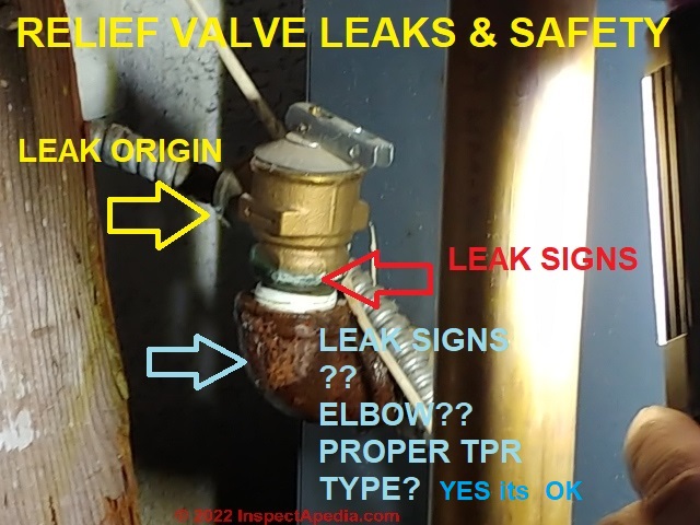
A series of anomalies occurred in the boiler room that evening. The steel compression tank for the hydronic loop flooded, leaving no room for expansion. Water will expand at 3% of its volume when heated from room temperature to 180° F. When the burner fired, the expansion of the water increased the system pressure within the boiler. The malfunctioning operating control did not shut off the burner at the set point which caused the relief valve to open.
The brass relief valve discharge was installed with copper tubing piped solid to a 90° ell on the floor and the tubing further extended to the floor drain. The combination of hot water and steam from the boiler caused the discharge copper tubing to expand, using the relief valve as a fulcrum. The expansion of the copper discharge tubing pressing against the floor was enough to crack the brass relief valve, flooding the boiler room. The damage was not discovered until the next morning, several hours after the leak occurred. Thousands of dollars in damage was sustained and luckily no one was injured.
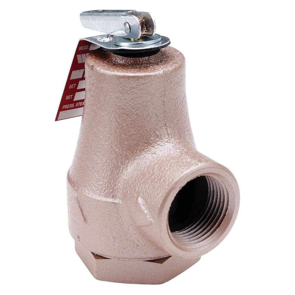
Each boiler requires some sort of pressure relieving device. They are referred to as either a safety, relief or safety relief valve. While these names are often thought of as interchangeable, there are subtle differences between them. According to the National Board of Boiler and Pressure Vessel Inspectors, the following are the definitions of each:
• Safety valve— This device is typically used for steam or vapor service. It operates automatically with a full-opening pop action and recloses when the pressure drops to a value consistent with the blowdown requirements prescribed by the applicable governing code or standard.
• Relief valve— This device is used for liquid service. It operates automatically by opening farther as the pressure increases beyond the initial opening pressure and recloses when the pressure drops below the opening pressure.
• Safety relief valve— This device includes the operating characteristics of both a safety valve and a relief valve and may be used in either application.
• Temperature and pressure safety relief valve— This device is typically used on potable water heaters. In addition to its pressure-relief function, it also includes a temperature-sensing element which causes the device to open at a predetermined temperature regardless of pressure. The set temperature on these devices is usually 210°.
• Relief valve piping— The boiler contractor installed a bushing on the outlet of the safety relief valve. Instead of 1 1/2-in. pipe, the installer used 3/4-in. pipe. When asked about it, he answered that he did not have any 1 1/2-in. pipe but had plenty of 3/4-in. pipe. I explained and then had to show the disbelieving contractor the code that states that the relief valve discharge piping has to be the same diameter as the relief valve outlet (see 2012 International Mechanical Code, 1006.6). By reducing the discharge pipe size, the relieving capacity of the safety valve may not be adequate to properly relieve the pressure inside the boiler, causing a dangerous situation.
The code also states that the discharge material shall be of rigid pipe that is approved for the temperature of the system. The inlet pipe size shall be full diameter of the pipe inlet for the relief valve. Some manufacturers suggest using black iron pipe rather than copper tubing. If using copper, it should have an air space that allows expansion should the relief valve open to avoid the accident that I referenced above. The discharge piping has to be supported and the weight of the piping should not be on the safety relief valve. Valves are not permitted in the inlet piping to or discharge piping from the relief valve. If you are using copper tubing on discharge piping, verify that there is room for expansion.
• Installation— Read the manufacturer’s installation manual as each may have different requirements. For instance, Conbraco requires that the discharge piping must terminate with a plain end and use a material that can handle temperatures of 375° or greater. This will preclude PVC or CPVC pipe for the discharge piping. The instruction manual for its model 12-14 steam relief valve stipulates that you cannot use a pipe wrench to install it. That would be good to know.
I once visited Boiler Utopia as the floor was clean and waxed. All the pipes were covered and exposed pipes were painted. There were large stickers detailing what was inside each pipe as well as directional arrows. Nothing was stacked next to the boilers. Yellow caution lines were painted on the floor around each boiler. I was in heaven. As I walked around the rear of the boiler, something clicked and triggered a warning bell. The discharge of the relief valve piping was about 6 in. from the floor but instead of a plain or angled cut end, the pipe had a threaded pipe cap on the termination. I asked the maintenance person about it and he said that the valve was leaking all over his newly waxed floor and this was the only way he could stop it. When I said that the discharge pipe should not have been threaded, he explained that it was not threaded and he had to take it to the local hardware store to thread it. I informed him that the cap had to be removed. We cut the pipe on an angle to prevent this.
• Steam boiler— Most manufacturers recommend a drip pan ell on the discharge of the steam boiler relief valve to eliminate the weight of the discharge piping on the relief valve. Some codes require the discharge to be vented outdoors.
• Testing— I will ask the attendees in my classes, “How often do you test the relief valves?” Most do not make eye contact and when I follow up with, “Why are they not tested?” I often hear that opening the relief valve will cause it to leak. I suggest that you refer to each manufacturer’s directions for testing. For instance, one will recommend once a year while another recommends twice a year. One manufacturer says, “Safety/relief valves should be operated only often enough to assure they are in good working order.” I am not sure what that even means. You want to also verify the proper test procedure as some will only want the relief valve tested when the boiler is at 75% of the rated pressure or higher of the relief valve.


 8613371530291