
gas cylinder regulator safety valve free sample

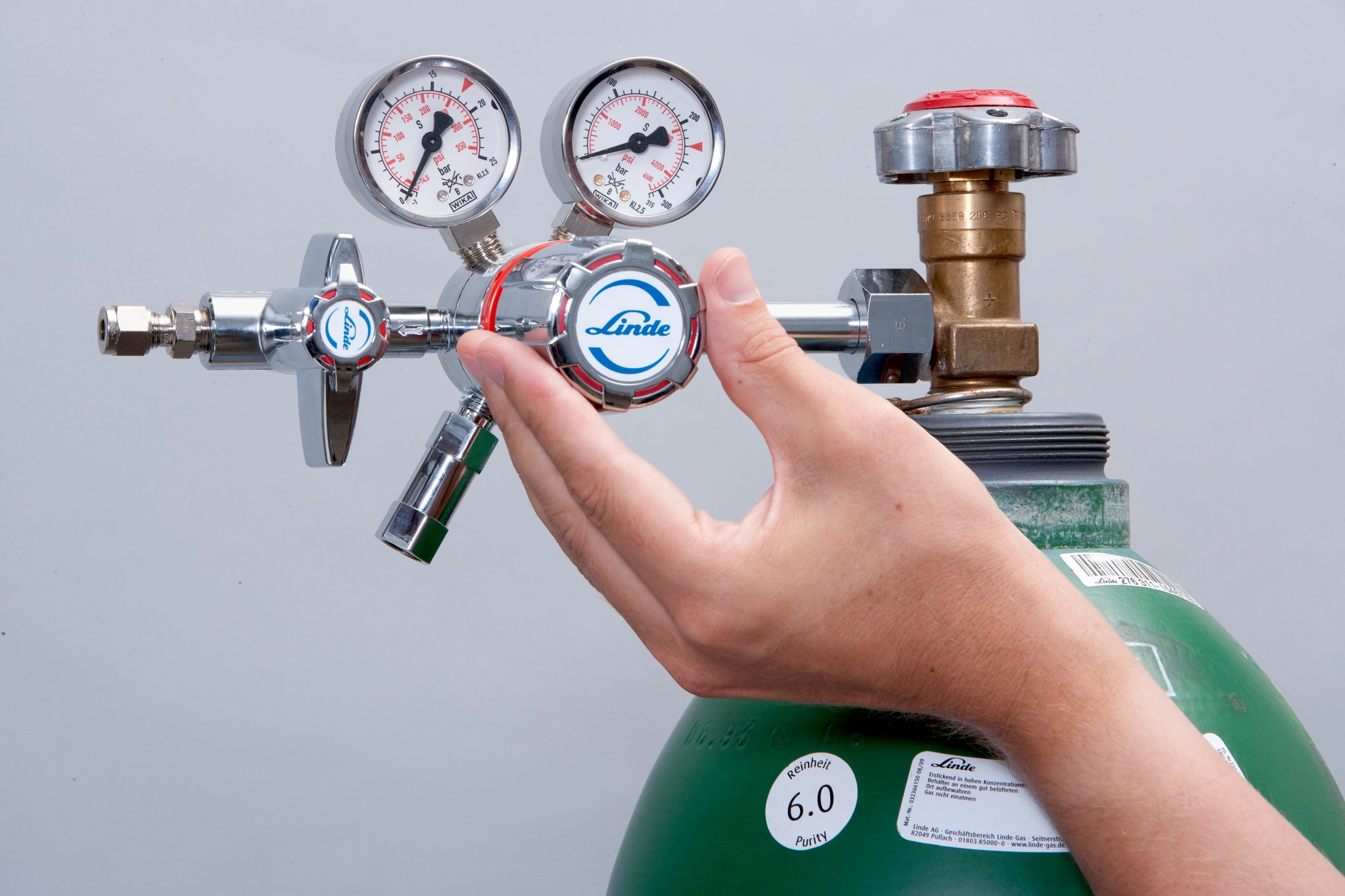
Pressure regulators reduce the high pressures of the stored gas in the cylinder to lower pressures that can be safely used in an operating system. Proper regulator selection is critical for both safety and effectiveness of operating systems. Regulators are designed to control pressure; they do not measure or control flow, unless equipped with devices such as a flow meter specifically designed for such purposes.
Regulator connections to cylinder valves must be completely free of dirt, dust, oil, and grease. "Crack" the valve slowly (by opening the valve slightly and then reclosing it) before attaching the regulator in order to blow out dust and debris from the opening. Note: Cylinders containing highly toxic gases should not be "cracked".
Regulators are attached to the cylinder, or manifold, at the inlet connection. This connection should be tested for leaks with a non-petroleum based product. Note that many soaps contain petroleum! The connection is marked with a Compressed Gas Association (CGA) number and will be left-hand or right-hand threaded to match the nut or fitting. This prevents a piece of incompatible gas equipment from being connected to the wrong gas supply.
Never use damaged or defective equipment. In fact, it"s best not to use a regulator that you do not know the history of - it may have been misused or repaired by an unauthorized person. Refer any problems or defects to the manufacturer for recommendations and authorized repair.
Opening a Regulator - Stand on the valve side of the cylinder at arms length so you do not have to reach in front of the regulator face. Turn your head away from the regulator and open the valve, turning counter clockwise, to blow out dust and debris, and then reclose the valve.
Changing a Regulator - Close the valve and drain the regulator by backing out the adjusting screw. Disconnect the regulator, making sure not to touch the nut and gland areas. Connect the regulator to the new cylinder.
Closing a Regulator - Turn the valve clockwise to close the valve. Drain the regulator by turning (opening) the adjusting crew to release any gas. Reclose the adjusting screw.
Recommendation: To provide easier access and additional safety, purchase wall-mounted regulators which connect to the supply cylinder by hose. This will reduce the handling of the regulator and reduce the likelihood of damage.
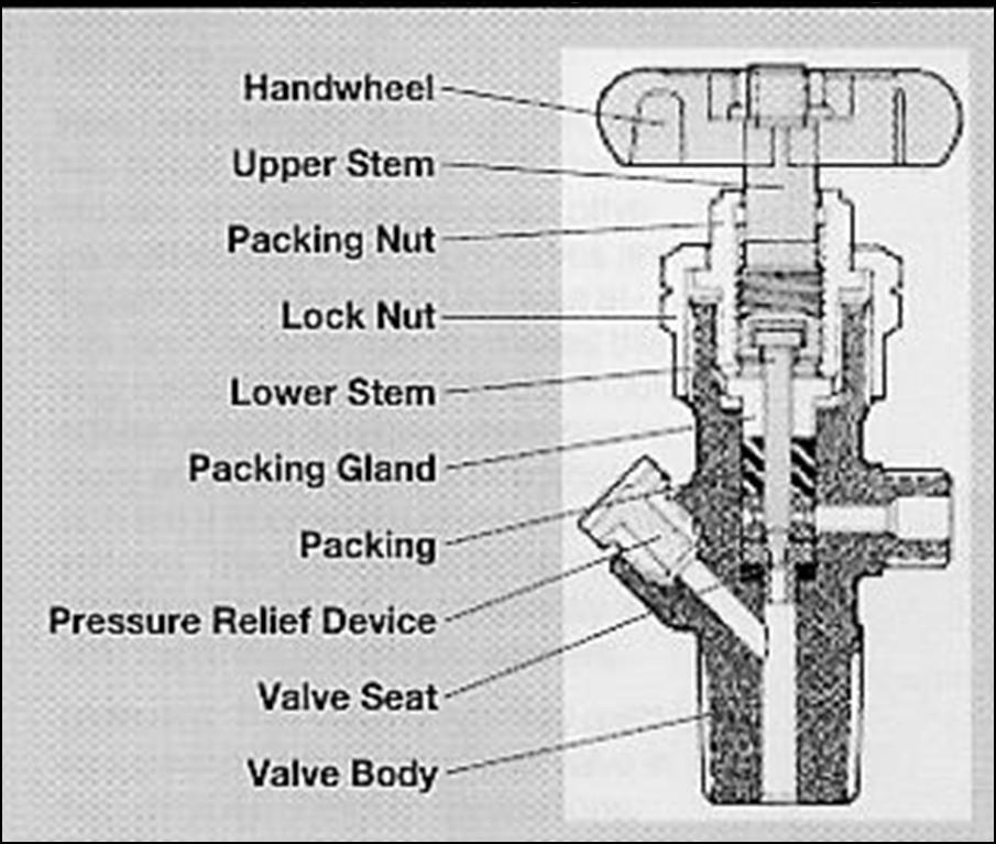
Diaphragm Valve - This valve uses a two piece stem separated by non-perforated diaphragms. These diaphragms prevent leakage along the valve stem. The lower part of the stem is encased in a spring, which forces the stem away from the seat whent eh valve is opened. The upper stem is threaded into the diaphragm retainer nut. When the handwheel is rotated to the closed position, the upper stem pushes on the diaphragms, which deflect downward, forcing the lower stem against the valve seat. Advantages of this type of valve are that they provide superior leak integrity and have no threads or lubricants in the gas stream to generate particles or contaminants. This type of valve is required for mos
Compressed gas cylinders shall have a pressure relief device installed to prevent the rupture of a normally pressurized cylinder when inadvertently exposed to fire of high temperatures. There are four basic types of pressure relief devices:
Rupture Disk Devices - A flat disk typically made of metal that is designed to burst at a predetermined pressure to permit the release of gas. The pressure rating of the disk is typically stamped onto the face of the device. Examples of gases using this type of device include compressed air, argon, helium, nitrogen, and oxygen.
Fusible Plug Devices - A plug made of fusible metal designed to yield or melt at low temperatures (usually 165 or 212 degrees F). The temperature rating of the fusible metal is stamped onto the face of the device. An examples of a gas that uses this type of device is acetylene.
Combination Ruture Disks/Fusible Plug Devices - A rupture disk backed by a fusible plug. In the event of a fire, the fusible metal melts and cylinder overpressure is relieved by the bursting of the disk. The burst pressure of the disk and the melting point of the plug will be marked with the ratings. Medical grade gas cylinders typically have this type of pressure relief device.
Pressure Relief Valves - A spring-loaded valve opens when the cylinder pressure exceeds the pressure setting of the spring to discharge contents. Once the cylinder pressure decreases to the valve"s pressure setting, the valve will normally reseat without leakage.
Demand flow regulator (DFR) is designed for use with instruments that utilize a pump to draw the calibration gas. This regulator provides the exact amount of gas that the instrument pump requires. This type of regulator makes calibration quick and easy by eliminating the need for sample bags, flow meters, or special operator training. In addition, it saves calibration gas because it only transfers as much gas as the instrument demands.
Also known as a pressure reducing regulator, vacuum actuated regulator, or sample regulator.Compatible for use with- REG-DF-1,N600 1001 33, 18102509,51700, 1419-216, 75-DFR
Calibration gas cylinder regulators connect to calibration gas cylinders to help regulate the gas out of the cylinders. Used for calibration gases and industrial hygiene monitors.

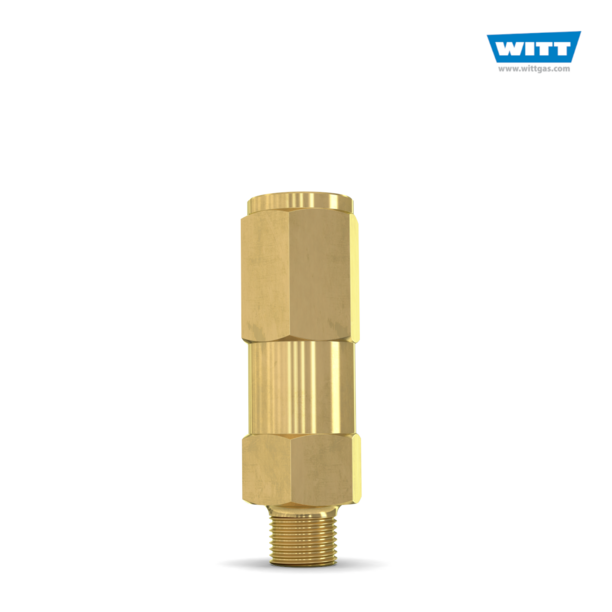
WITT is a manufacturer of Pressure relief valvesor Safety relief valves for technical gases. They are designed to protect against overpressure by discharging pressurized gases and vapors from pipelines, pressure vessels and plant components. Safety relief valves (SRV) are often the last line of defense against explosion – and such an explosion could be fatal. Other common names for safety relief valves are pressure relief valve (PRV), safety valve, pressure safety valve, overpressure valve, relief valve or blow-off valve.
WITT safety valves are very precise. They are individually preset to open at a predetermined pressure within the range 0.07 to 652 Psi. Their small size and orientation-independent installation allow a wide range of connection options. WITT relief valves also stand out due to their high blow-off flow rates of up to 970m³/h. They can be used within a temperature range of -76° F to +518°F and even with very low pressures.
For maximum safety, WITT undertakes 100 % testing of each safety relief valve before it is delivered. In addition, WITT offers individual testing of eachsafety valveby the TÜV, with their certificate as proof of the correct set pressure.
WITTsafety relief valvesare direct-acting, spring-loaded valves. When the preset opening pressure is reached, a spring-loaded element in the valve gives way and opens, and the pressure is relieved. Once the pressures are equalized, the valve closes automatically and can be reactivated any time the pressure rises again. Depending on the application and the nature of the gas, the safety relief valvescan either discharge to atmosphere, or via a connected blow-off line. The opening pressure of the safety valves is preset by WITT at the factory according to the customer’s requirements.
Safety relief valvesare used in numerous industries and industrial applications where, for example, gases pass through pipelines or where special process vessels have to be filled with gas at a certain pressure.
For most industrial applications using technical gases, brass is usually the standard material of construction of thesafety relief valvebody/housing. For the use of pressure relief valves with aggressive and corrosive gases, the housings are made of high-quality stainless steel (1.4541/AISI 321, 1.4404/AISI 316L, 1.4305/AISI 303 or 1.4571/AISI 316Ti). The use of aluminium as a housing material is also possible.
Depending on the type of gas used and individual customer requirements, various sealing materials and elastomers are available to ensure the safety of your systems under even the most difficult conditions.
WITT pressure relief valves are available with different connections. In addition to the standard versions with the usual internal or external threads, special versions with KF or CF flanges, VCR or UNF threads can also be ordered. Special adapters for connecting the safety relief valve to a blow-off line are also available.

Unscrew the pressure adjustment knob until the internal spring is no longer compressed, and ensure that the regulator outlet valve is closed, if one is installed. An outlet valve serves to prevent air from leaking from an open regulator into the gas lines, and is a necessity for most GC gases. An additional in-line purge valve is useful for purging air from a reconnected gas line.
Face the gas cylinder with the pressure regulator positioned on the side opposite to you, slowly open the high pressure cylinder valve, and allow the internal pressure to build up slowly in the regulator. Shut the valve immediately if an audible gas leak occurs. For gases other than air or nitrogen, use an electronic leak detector around the high-pressure fitting, the regulator gauge, and the cylinder shut-off valve to ensure there are no leaks.
Gas regulators have a finite lifetime. Most regulators will last for years with normal GC use, but each regulator should be tested upon installation and periodically after that to identify potential premature failure.
To test a regulator, first check the high-pressure gauge-it should read between 1800 and 2600 psig (12–18 mPa) for a new cylinder, depending on the type of cylinder and gas. If the gauge reading is very low, then the cylinder is not full or the gauge is defective. In this case, the best procedure is to temporarily install another suitable regulator to check the cylinder pressure. If necessary, replace the cylinder or the defective regulator. Never try to replace a gauge on a regulator or to repair any other regulator component. Only a regulator manufacturer can do that.
Next, observe the outlet pressure gauge for a few minutes, with the outlet valve closed. There should be no observable pressure increase. If the outlet pressure does go up when the pressure adjustment is fully withdrawn, then the regulator has a leak from the high-pressure side and must be returned to the manufacturer for repair or replacement. To complete checking the high-pressure side, close the cylinder valve and wait 2 min-the high-pressure gauge indication should not decrease. Any loss of high pressure with the cylinder valve closed also indicates a leak that will require repair or replacement.
Now, with the outlet valve still closed, re-open the high-pressure cylinder valve completely. Adjust the regulator outlet pressure to its operating level, which usually lies between 40 and 90 psig (275–600 kPa) for GC gases. If the outlet pressure gauge rises quickly to a high pressure, or if the gauge fails to attain the desired level despite increasing the pressure adjustment, shut off the cylinder valve and replace the regulator.
At this point an in-line purge valve can be used to bleed out any air that may have entered the regulator. Open the outlet valve slowly and pressurize the connecting tubing. The outlet pressure gauge may drop momentarily, but it should settle back quickly to its set point. Allow a few seconds to bleed gas from the purge valve, if one is used, and then close it. As a last step, I check the dynamic operation of a regulator by momentarily shutting off the cylinder valve while the regulator is delivering flow. The high-pressure gauge will start to drop as the gas is consumed, but the outlet pressure should be nearly steady as long as at least 2–3 times the outlet pressure remains on the high-pressure side. Restore the cylinder valve to its fully open position. Sometimes it is convenient to run this test while waiting for the gas lines to be purged of any small amount of air that entered during installation.
As with all components in the GC supply gas stream, the connecting tubing and fittings need to be free of contaminants and leaks, and they must be rated to withstand the highest possible pressure to which they could be subjected in the event of pressure regulator failure. A good figure of merit to use is at least twice the opening pressure of the safety relief valve in the downstream pressure side of the regulator, which will be greater than the highest outlet pressure the regulator is designed to deliver. Even so, higher-pressure transients are possible with failure of the high-pressure side of the regulator, until the contents of the cylinder have been vented.
For the above reasons, GC installations should never use polymeric tubing or plastic fittings. Although such materials are suitable for many liquid chromatography (LC) applications, they are not suitable for GC use for three reasons. First, polymeric materials may contaminate the gas stream. Atmospheric gases, namely water and oxygen, may diffuse into the gas stream, and the tubing can emit traces of plasticizers. Second, polymeric tubing and fittings may fail and burst at high pressures. And third, when routed behind a GC instrument, polymeric tubing and fittings may be exposed to the high-temperature air exhaust from a GC oven that is cooling down, which could cause an immediate tubing failure or at least weaken a section of the tubing.
I’ve seen a few installations that use aluminum tubing, but this is not a suitable choice. Although aluminum possibly is less expensive than copper or stainless steel, it lacks the ductility of other available metal tubing, and it will rapidly develop metal fatigue cracks and failures unless it is mechanically constrained. The majority of GC gas supply installations will flex the connecting tubing during tank changes, and with some GC systems the external connecting tubing is flexed when the top cover is lifted. In addition, aluminum tubing does not fare well in swaged fittings that must be disconnected and remade.
When the residual cylinder pressure drops below about three times the regulator outlet pressure, which is around 250 psig (1.7 MPa), it’s time to replace the cylinder. Don’t allow the internal cylinder pressure to go to zero; it will force the gas supplier to perform extra cleaning on the cylinder because they cannot assume it has not been contaminated. In addition, running down the cylinder pressure will cause the regulator’s outlet pressure first to increase slightly and then drop off toward zero, which will cause retention time and detector stability problems. First bring a new cylinder into the laboratory, and then swap the old and new cylinders as follows.
The pressure regulator must be relieved of internal gas pressure before it is disconnected; otherwise a sudden burst of gas may result. First, turn the GC thermal zones off and allow them to cool. Turn off the detectors as well. Then turn off the high-pressure cylinder valve and allow both the high-pressure and outlet pressure gauges to approach zero. It may be necessary to bleed gas off at the GC by increasing a flow or pressure setting temporarily. Next, set the pressure adjustment on the regulator fully off and close the regulator outlet valve. Turn the GC flow and pressure settings to zero to prevent air from diffusing back into the gas lines and filters. Finally, loosen and remove the regulator from the gas cylinder, and install the cylinder cap.
Carefully secure the regulator while exchanging the cylinders. A small strap or chain works well to hold it onto a neighboring device, or just place it on a flat surface. Don’t leave it hanging by the connecting tubing, which will only stress the tubing and could allow the regulator to fall some distance and be damaged.
If a regulator will be removed from use, even for a day, it should be detached from the connecting tubing and stored in a dust-free environment. If gas filters are in-line, be sure they are filled with gas and then if possible, seal the filters’ inlets and outlets before exposing the gas supply lines to the open air.
Return used cylinders promptly. Keeping empty cylinders on hand will accumulate cylinder demurrage charges and waste space that could be put to better use.
Laboratory workers can ensure high-pressure gas cylinder safety by following a few simple procedures and installation guidelines. Proper cylinder restraint, appropriate regulator installation and operation, and suitable connecting tubing and fittings all will yield improved safety and better GC results. Cylinder transportation is the most hazardous part of gas handling in the laboratory environment. Perhaps risky gas handling behavior is due to simple carelessness and a rush to get the instruments up and running again, but the potential cost and impact of not following safe procedures far outweighs the loss of a few minutes of productive lab time.
We will explain compressed gas cylinder Safety guidelines in the term of identification, storage, handling, hazards, precaution and use of industrial compressed gas cylinders.
Argon, oxygen, acetylene, gases are compressed under high pressure and can be stored inside the cylinder for easy transportation and storage at working site.
Cylinders shall not be subjected to contact with direct flame, electric arc, molten metal, and other sources of heat, corrosive material or corrosive environment.
(2) Has a boiling point of 20°C or less at an absolute pressure of 101.3 kPa and that is liquefied, non-liquefied, or in solution. Gases that have no health or physical hazard properties are not considered to be compressed gases until the pressure in the packaging exceeds an absolute pressure of 280 kPa at 20°C. (Source: NFPA 55-2013, 3.3.49.1)
Cylinder : A pressure vessel designed for absolute pressures higher than 276 kPa and having a circular cross-section. It does not include a portable tank, multiunit tank car tank, cargo tank, or tank car. (Source: NFPA 55-2013, 3.3.29)
All cylinders that are received for use on site shall be colour coded on the shoulder of the Cylinder (curved part). The colour coding is intended to identify the properties of the gas in the cylinder. A number of industrial gases have been assigned a specific colour.
Where an industrial gas does not have a specific colour, the properties of the gas shall be indicated. For gases with two properties they shall be indicated by two concentric bands.
The colour coding described only applies to the shoulder, or curved part, at the top of the cylinder and is used to identify the properties of the gas in the cylinder.
All gas cylinders are required to be labelled to indicate the contents of the cylinder. Below is an example of a typical label, with an explanation of the various items that are to be displayed. It must always be remembered that the label is the means of identifying the contents of the cylinder. The colour of the cylinder is only a guide.
A suitable area dedicated for the storage of industrial gas cylinders shall be identified and provided for the storage of industrial gas cylinders. All cylinders shall be secured in an upright position and secured with the protective caps at all times in designated cylinder storage areas. All cylinders shall be labelled, marked and stored in accordance with their contents.
A suitable location within the site shall be established for the storage of gas cylinders in accordance to the following guidelines:An area where the cylinders has minimal exposure to excessive temperature, physical damage or tempering. Compressed gas cylinders shall not be exposed to direct temperatures exceeding 38o
The storage area shall be enough to contain the projected quantity of compressed gas cylinders that may be stored on site on any given time and to allow segregation distances between incompatible gases.
2) Construction LayoutCompressed gas cylinders storage area shall be delimited with such materials as chain links, fence or open block for the full height and width of the opening. Materials used to construct the storage area shall be non-combustible.
Cylinders shall not be placed directly onto the ground where they can be exposed to conditions which could cause corrosion on the base of the cylinders. They shall be placed on a slightly elevated and smooth surface, such as concrete flooring.
All cylinders shall be stored upright and restrained from toppling (e.g. secured at two levels with chain links, ropes) and shall not be propped against a wall or bench.
Full cylinders shall be kept separated from empty cylinders and sign posted to indicate ‘Full Cylinders’, ‘Empty Cylinders’. A partition shall be established in the storage area for this purpose.
Oxygen cylinders shall be stored separately (minimum of 6 meters or twenty feet) from all other sources of combustible gas, or by means of a non-combustible barrier at least five feet (two meters) high having a fire-resistant rating of at least one-half hour.
Cylinders of the same type shall be placed together. Incompatible gases shall be either separated by a distance of 6 meters or by means of a non-combustible barrier at least 2 (two) meters high having a fire-resistant rating of at least one-half hour. All empty cylinders shall be stored separately from all other cylinders.
Cylinders shall be placed in a manner that they do not become part of an electrical circuit and shall be kept away from piping systems and layout / cutting tables that may be used for grounding electrical circuits.
4) Oil, grease and other contaminantsOil or grease ignites violently in the presence of high pressure oxygen. Cylinders and fittings shall be kept clear from all sources of contamination such as oil barrels, cranes, drive belts etc.
Suspended work platform / basket shall not be used to lift compressed gas cylinders. Lifting of cylinders by direct slinging or lifting it off its valve protection collar is strictly prohibited.
1) Care of Compressed Gas Cylinderin useLoose dirt shall be cleared by ‘sniffing’ some gas to the atmosphere (opened slowly and then closed immediately) before connecting the regulators to the valve. This shall be
The standard key issued by the supplier for the cylinders shall be used. The leverage of keys shall not be increased and badly worn keys shall be removed.
When oxygen or fuel cylinders are connected to manifolds or headers, the manifolds shall be of a proper design with one or more pressure regulators, pressure relief devices and anti-flashback arrestors.
When compressed gas is supplied to process equipment from cylinders, the proper risk assessment shall be carried out. If the result of risk assessment requires, pressure relief devices shall be installed between the equipment and regulator(s) of the cylinder(s).
A typical oxy-fuel setup is shown in below figure. Flashback arrestors and check valves shall be installed on all oxygen and acetylene cutting gear. The flashback arrestor shall be installed at the regulator end and the check valve at the cutting torch end of each hose while in operation.
The following precautions shall be taken when using hoses connected to compressed gas cylinders;Only hoses that of a good quality and fit for the task shall be purchased. Substandard quality hoses crack and leak over a certain period of time.
Hoses used to convey gases are each assigned a specific colour. All hoses used on the project shall conform with the colour coding requirements as indicated in the table below.GasColour of hose
Torches shall not be lighted up until sufficient time has elapsed for the gas in the hose to reach the working pressure and that any air in the hose has been expelled.
No one except the owner or a person approved by the owner shall refill a compressed gas cylinder. All refill operations shall take place at the supplier / manufacturer location and shall not be carried out in the project site.
Pressure regulators are available in two types: relieving and non-relieving. Both can give the maximum volume of flow needed while keeping outlet pressure constant. The difference between relieving and non-relieving regulators depends on whether they self-release or trap excess pressure. At Air Logic, we offer both relieving and non-relieving pressure regulators that can be either preset or adjustable.
A relieving regulator releases excess pressure through a relief valve, a hole in the middle of the diaphragm. When air pressure exceeds the acceptable limit of a system, the relieving regulator opens a vent to allow the air to escape. A hissing sound usually indicates the release of air. There is no need to add an extra relief valve to the flow system since the relieving regulator performs this function on its own.
A non-relieving regulator restricts airflow once it exceeds the setpoint. There’s no vent path in a non-relieving regulator so the gas stays in the system. These regulators require extra care because they can become dangerous if excess pressure builds up without being released. In a closed system, it is important to have a relief valve downstream. Alternatively, an open system design should be implemented downstream of the regulator to prevent the build-up of excessive pressure.
Non-relieving regulators are most beneficial when dealing with hazardous or expensive gases. By trapping these gases for safe or controlled release, operators ensure the safety and efficiency of the entire facility.
Knowing the difference between a relieving and non-relieving regulator will help you make an informed decision for your application. Air Logic produces a vast selection of pneumatic equipment and control components, including relieving and non-relieving regulators.
Our Modular Subminiature Relieving Regulator is designed to regulate pressure accurately with minimal consumption. For non-relieving regulator applications, our Modular Subminiature Non-Relieving Regulator provides accurate pressure regulation without pressure bleeding.
When transporting chemicals, you need to be confident that the integrity of your product will be maintained and the people handling your containers will be protected. Swagelok offers a wide selection of cylinders that are compliant with DOT, Transport Canada and TPED standards for transportation of chemicals. These cylinders feature consistent wall thickness, smooth internal neck transitions for easy cleaning, and heavy-wall connections that resist flaring.
Compressed gases are stored in heavy-walled metal cylinders designed, produced and tested for use with compressed gases. Cylinders are made in a wide variety of sizes and shapes. They range from small lecture bottles, often used for demonstration purposes, to large cylinders over 3 metres long. Cylinders for transportation must meet CSA standard CAN/CSA-B339 "Cylinders, Spheres and Tubes for the Transportation of Dangerous Goods". This standard covers requirements for the manufacturing, inspection, testing, marking, requalification, reheat treatment, repair, and rebuilding of cylinders, spheres, and tubes (containers) for the transportation of dangerous goods. In addition, it includes the requirements for the qualification of new designs and registration requirements. You should also consult CAN/CSA-B340 "Selection and Use of Cylinders, Spheres, Tubes, and Other Containers for the Transportation of Dangerous Goods, Class 2".
Cylinders that meet these criteria are often referred to as "TC approved" cylinders. Cylinders are permanently marked, typically on the shoulder or the top surface of its neck.
Compressed gas cylinders must be connected only to regulators and equipment designed for the gas in the cylinder. Since connecting the wrong equipment can be dangerous, a number of different standard cylinder valve outlets are available for different classes of gas. For example, these standard connections prevent the valve connection for a flammable gas from fitting the connections for an incompatible gas, such as an oxidizing gas.
Most compressed gas cylinders have valve caps or some other method of protecting the valve from damage during handling and transportation. A dust cap may be placed over the valve outlet itself to help keep it clean.
Most cylinders have one or more safety-relief devices. These devices can prevent rupture of the cylinder if internal pressure builds up to levels exceeding design limits. Pressure can become dangerously high if a cylinder is exposed to fire or heat, including high storage temperatures.
There are three types of safety-relief devices. Each relieves excessive gas pressures in a different way:Safety- or Pressure-Relief Valves: These valves are usually a part of the cylinder. They are normally held closed by a spring. The force holding the valve closed is set according to the type of gas in the cylinder. The valve opens if the cylinder pressure exceeds the set safety limit. Gas is released until the cylinder pressure drops back to the safety limit. The valve then closes and retains the remaining gas in the cylinder.
Rupture Discs(also known as frangible or bursting discs): These discs are usually made from metal. They burst or rupture at a certain pressure, releasing the gas in the cylinder. The bursting pressure is designed so that the disc ruptures before the cylinder test pressure is reached. These devices cannot be reclosed, so the entire contents of the cylinder are released.
Fusible Plugs(also called fuse or melt plugs): Temperature, not pressure, activates fusible plugs. These safety devices are used where heat could initiate an explosive chemical reaction. A pressure-relief valve or rupture disc acts too slowly and too late to prevent rupture of the cylinder if an explosive reaction has already begun. The fusible plug releases the gas before the hazardous reaction can begin. Fusible plugs are made of metals that melt at low temperatures. For example, acetylene cylinders have a fusible plug which melts at about 100°C (212°F). This temperature is safely below the temperature at which hazardous polymerization may occur.
Not all compressed gas cylinders have safety devices. Some gases are so toxic that their release through a safety device would be hazardous. Cylinders for these gases are built to withstand higher pressures than normal cylinders. When these "toxic gas" cylinders are involved in a fire, the area must be evacuated.
Substitution can be the best way to avoid or reduce a hazard. But it is not always easy or even possible to find a less hazardous substitute for a particular compressed gas used for a certain job. Speak to the chemical supplier to find out if safer substitutes are available. For example, in some cases, methylacetylene-propadiene (MAPP) gas, propylene, propane or mixtures of liquefied petroleum gas can be substituted for acetylene as fuel gases for cutting, welding and brazing. These gases are more stable and can be stored in normal cylinders. Their flammable limits are much narrower than those of acetylene (e.g., 3.4 to 10.8 percent for MAPP versus 2.5 to 82 percent for acetylene), so they represent a reduced fire hazard.
Sometimes, process changes or modifications can reduce a material"s hazards. For example, many cylinders of the same gas may be used in different areas of a workplace. Installing fixed pipelines connected to a central gas supply in a safe area can often reduce the hazard. It can also reduce the need for many sets of portable equipment supplied through flexible hoses. Similarly, ordering cylinders equipped with flow limiting restrictors can minimize the hazards of a sudden failure of a process gas line.
Assess the specific ways your workplace stores, handles, uses and disposes of its compressed gases. An assessment can reveal if existing ventilation controls and other hazard control methods are adequate. Some workplaces may need a complete system of hoods and ducts to provide acceptable ventilation. Others may require a single, well-placed exhaust fan. Storage facilities for particularly hazardous materials such as chlorine, may require an additional emergency ventilation system, or continuous monitoring with appropriate alarms. Other workplaces using small amounts of inert gases may require no special ventilation system.
Make sure ventilation systems are designed and built so that they do not result in an unintended hazard. Ensure that hoods, ducts, air cleaners and fan are made from materials compatible with the gas used. Systems may require explosion-proof and corrosion-resistant equipment. Separate ventilation systems may be needed for some compressed gases to keep them away from systems exhausting incompatible substances.
Store compressed gas cylinders in compliance with the occupational health and safety regulations and fire and building codes applying to your workplace. These laws may specify the permissible kinds of storage areas and the construction of these storage areas. They may also specify the kinds and amounts of different gases that can be stored in each safe storage area.
Inspect all incoming cylinders before storing to ensure they are undamaged and properly labelled. Do not accept delivery of defective cylinders. Be sure they are not giving off odours, visible fumes or hissing sounds. Check that the cylinder was last tested within the required time (usually 5 or 10 years, but some containers may be as low as 3 years or as long as 12 years).
Also check that the cylinder labels are intact and that they match other identifying markings on the cylinder. Do not rely on cylinder colour to identify the gas. Different suppliers may use different colours for cylinders of the same gas. In addition, colours appear different under artificial lights and some people are colour blind. Gases that cannot be clearly identified should not be used.
Call compressed gases by the name on the supplier label. This reduces confusion, promotes recognition of the hazards involved and precautions to take, and can prevent accidental use of the wrong gas. If oxygen is called "air," someone who wants air to run a tool may use oxygen with possible serious results. Leave the valve cap securely in place until the cylinder is to be used. Inspect the cylinder valve by looking through the ports in the valve cap. Do not accept dirty, rusted or otherwise damaged valves and fixtures.
Always transport cylinders with valve caps or other valve protection in place. Pulling cylinders by their valve caps, rolling them on their sides or dragging or sliding them can cause damage. Rolling cylinders on their bottom edge ("milk churning") may be acceptable for short distances. Never lift cylinders with magnets or chain or wire rope slings. Transport cylinders on specially built hand carts or trolleys or other devices designed for this. All transport devices should have some way of securing cylinders to prevent them from falling.
Store compressed gas cylinders separately, away from processing and handling areas, and from incompatible materials. Separate storage can minimize personal injury and damage in case of fires, spills or leaks. Many compressed gases can undergo dangerous reactions if they come in contact with incompatible materials (gases, liquids or solids), so store them apart from each other. For example, store oxidizing gases at least 6 metres (20 feet) away from fuel gases or other combustible materials, or separate them with an approved fire wall. Check the reactivity information and storage requirements sections of the MSDS for details about which materials are incompatible with a particular compressed gas. The National Fire Code addresses requirements for segregation of different gases in storage.
If compressed gas cylinders are stored outside, use a well-drained, securely fenced area. Keep them on a raised concrete pad or non-combustible rack. Protect cylinders from the weather and do not allow them to stand directly on wet soil as this can cause corrosion.
Indoor storage areas must have walls, floors and fittings made of suitable materials. For example, use non-combustible building materials in storage areas for oxidizing gas and corrosion-resistant materials in storage areas for corrosive gas. Make sure floors are level and protect cylinders from dampness. Avoid overcrowding in storage areas or storing cylinders in out-of-the-way locations.
Always chain or securely restrain cylinders in an upright position to a wall, rack or other solid structure wherever they are stored, handled or used. Securing each cylinder individually is best. Stacking of groups of cylinders together offers some protection, but if this is done improperly, the entire group or individual cylinders could fall.
Follow the gas supplier"s recommendations for storage and use temperatures. To prevent excessive pressure buildup, never expose cylinders to temperatures above 52°C (125°F). Do not subject them to temperatures below -29°C (-20°F), unless they are designed for this. Cylinders that become frozen to a surface can be freed by using warm water (less than 52°C). Never apply direct heat to a cylinder.
When moving cylinders, securely fasten them to a suitable cylinder transporting device. At the site, chain or otherwise secure the cylinder in place. Remove the valve cap only after the cylinder has been safely installed then check the cylinder valve and fixture. Remove any dirt or rust. Grit, dirt, oil or dirty water can cause gas leaks if they get into the cylinder valve or gas connection.
There are four standard types of cylinder valve outlets to prevent interchanges of gas handling equipment between incompatible gases. Use only the proper equipment for discharging a particular gas from its cylinder. Never use homemade adaptors or force connections between the cylinder valve outlet and gas handling equipment.
Whether a compressed gas is a liquefied, non-liquefied or dissolved gas, the gas supplier can give the best advice on the most suitable gas discharge equipment and the safest way to use it for a specific job.
In general, do not lubricate any cylinder valves, fittings, or regulator threads, or apply jointing compounds and tape. Use only lubricants and sealants recommended by the gas supplier.
Cylinders stored in cold areas may have frozen valves. Use only warm water to thaw the valve or bring the cylinder into a warm area and allow it to thaw at room temperature.
Use only recommended keys or handwheels to open valves. Never use longer keys or modify keys to increase their leverage. Avoid using even the correct key if it is badly worn. Do not use pipe wrenches or similar tools on handwheels. Any of these practices could easily damage the valve seat or spindle.
Always open valves on all gas discharge equipment slowly. Rapid opening of valves results in rapid compression of the gas in the high-pressure passages leading to the seats. The rapid compression can lead to temperatures high enough to burn out the regulator and valve seats. Many accidents involving oxidizing gases result from burned out regulator and valve seats, usually caused by opening valves too quickly.
Do not use excessive force when opening cylinder valves--use no more than three quarters of a turn if possible. If a problem develops, the valve can then be closed quickly. Leave keys on cylinders when valves are open so the valve can be closed quickly in an emergency. Some cylinder valves, such as oxygen valves, have double seating. These valves should be fully opened, otherwise they may leak.
Do not use excessive force when opening or closing a cylinder valve. When closing, turn it just enough to stop the gas flow completely. Never force the valve shut.
Close cylinder valves when the cylinder is not actually in use. Do not stop the gas flow from a cylinder by just backing off on the regulator. Regulators can develop seat leaks, allowing pressure to build up in equipment attached to the regulator. Also if the cylinder valve is left open, foreign matter can enter the cylinder if the cylinder pressure drops lower than the pressure in attached equipment. Close the cylinder valve first and then close the regulator.
Manual valves are normally used on cylinders containing liquefied gases. Special liquid flow regulators are also available. If it is necessary to remove liquid as well as gas from a cylinder, discuss this with the gas supplier before ordering. Some liquefied gas cylinders have eductor tubes which allow the liquid to be withdrawn from the cylinder. The supplier can provide suitable cylinders and special instructions.
Do not remove gas rapidly. The pressure in the cylinder could drop below the required level. If this happens, or if rapid gas removal is needed, follow the gas supplier"s advice.
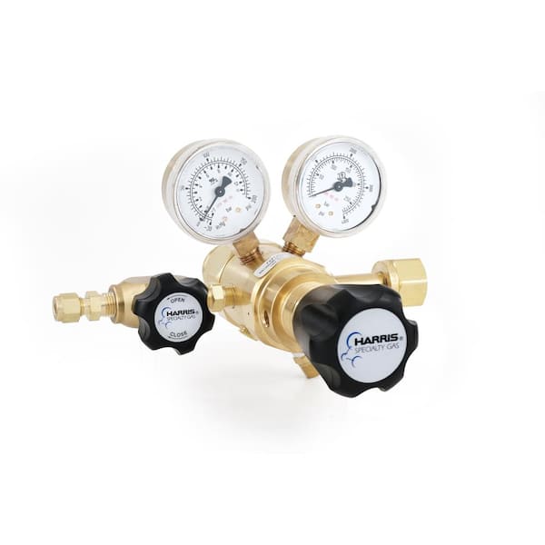
There are two basic types of automatic pressure regulators: single-stage, and double- or two-stage. Generally, two-stage regulators deliver a more constant pressure under more precise conditions than single-stage regulators. Sometimes, manual flow controls are used on non-liquefied gases. Fine flow control can be obtained, but an operator must be present at all times. Manual flow controls do not automatically adjust to pressure buildups in blocked systems.
Use the smallest practical cylinder size for a particular job. Do not keep cylinders longer than the supplier recommends. Compressed gas cylinders are mainly shipping containers. They are built to be as light as possible while remaining safe and durable. Do not drop cylinders or otherwise allow them to strike each other. Rough handling, including using cylinders as hammers or as rollers to move equipment, can seriously damage them.
Apart from the fact that it is illegal, it can be dangerous for non-specialists to refill cylinders or to change their contents. Explosions, cylinder contamination or corrosion can result.
All equipment used with compressed gases must be clean, properly designed and maintained, and made from materials compatible with the gas used. For example, acetylene forms explosive compounds in contact with copper, silver and mercury or their alloys, including bronze or brass containing more than 65 percent copper. Ammonia attacks brass and can react with mercury to form an explosive compound. Do not use mercury pressure gauges in ammonia systems.
In general, avoid pressurizing ordinary glass equipment. Use specially designed glass equipment and protective devices. Where cylinders are connected to a manifold or header, make sure specialists properly design and install the system. Use effective flashback arrestors on acetylene and other flammable gas systems.
Always follow the correct procedures for assembling and disassembling compressed gas equipment. Check that all the connections are clean and do not leak. Check for leaks, using the gas suppliers recommended method, after assembling and before starting to use equipment. Never use old clips or twisted wire for hose connections. If a hose works loose and flails around, serious injury could result. Poor hose connections are a common cause of accidents.
Acetylene under pressure can explode. Never use acetylene outside of the cylinder at pressures over 103 kPa (15 psig) unless you take special precautions. If an acetylene cylinder has been accidentally left on its side, set it upright for at least an hour before use. Otherwise, it will emit a burst of solvent instead of gas when the valve is opened.
Corrosive gases can "freeze" the valve stem, making it hard to open the valve. This results from the gas corroding the valve metal. Minimize "freezing" by rotating the valve stem at least once a day while the cylinder is in use. Also, flush the regulator or manual control valve with dry nitrogen or dry air as soon as possible after use.
Special cleaning procedures (equivalent to oxygen service) are required for all equipment to be used with oxidizing gases. There are several ways to do this. Contact your gas supplier for the best methods for specific systems.
Do not oil or grease any equipment that may contact oxidizing gases. Keep greasy hands, rags and gloves away from any part of the cylinder and fittings. Normal body oils are usually not hazardous, although it is a good practice never to touch any surface that may contact an oxidizing gas. Use lubricants and connection or joint sealants recommended by the gas supplier.
Always comply with applicable occupational health and safety laws when working in a confined space. When using compressed gases, including inert gases, in a confined space, be sure to check that all equipment connections are leak-tight. Remove cylinders or connected equipment that are not in use from confined spaces, even during short breaks. Check the air for oxygen levels (high and low). Also check for any possible toxic, corrosive or flammable gases before entering confined spaces and during prolonged work periods. Never work alone.
The amount of material remaining in a non-liquefied or dissolved gas (acetylene) cylinder is directly proportional to the cylinder pressure gauge reading. As the gas is used, the reading on the cylinder pressure gauge drops. When the cylinder pressure gauge reads zero, the cylinder is not really empty. The cylinder still contains gas at atmospheric pressure. Keep a slight positive pressure in the cylinder. Consider it "empty" when the cylinder pressure gauge reads about 172 kPa (25 psig) or when the cylinder will not deliver at least 172 kPa to the outlet pressure gauge.
The pressure in liquefied gas cylinders remains constant at a given temperature as long as any liquid remains in the cylinder. The only way to know how much material remains in a liquefied gas cylinder is to weigh the cylinder. The empty (tare) weight of the cylinder is stamped on its neck or valve stem. Record the net weight of the cylinder contents on a card attached to it. As with non-liquefied and dissolved gases, never empty the cylinder completely. Keep a small amount of material in the cylinder to maintain a slight positive pressure.
Keeping a positive pressure in an "empty" compressed gas cylinder helps to prevent back flow or suck back. This back flow is the drawing-back into the cylinder of contaminants or moist air from a higher pressure system or the atmosphere.
Keep the valves on all "empty" cylinders closed. This practice maintains a positive pressure in them. "Empty" cylinders with open valves can "breathe". Temperature increases or drops in atmospheric pressure can force gas out of the open valve of an empty cylinder. This release could result in hazardous conditions depending on the gas and how much is forced out. Temperature drops or increases in atmospheric pressure can cause air to be drawn in through the open valve. Air could cause a serious contamination and corrosion problem inside the cylinder. When a compressed gas cylinder is "empty," handle it as though it is full since it does contain gas.
Notify the gas supplier if the cylinder or any part of it is damaged or defective, contaminated, or may have been exposed to a possibly hazardous condition such as a fire or electric arc.
Take care when scrapping unserviceable cylinders. Before scrapping, first destroy the cylinder as a pressure vessel. Contact the gas supplier for advice on disposing of unserviceable cylinders.
*Note: Hanging things over a cylinder makes it harder to operate the valve. In addition, clothing may become saturated with a hazardous gas. Clothing saturated with either an oxidizing gas or flammable gas will catch on fire easily and burn intensely. Hang clothes that are even partly saturated with an oxidizing gas or fuel gas in a well-ventilated area for at least 15 minutes to remove trapped gas.
If other methods, such as engineering controls, are not available or effective in controlling exposure to compressed gases, wear suitable personal protective equipment (PPE). Choosing the right PPE for a particular job is essential. Material Safety Data Sheets (MSDSs) should provide general guidance. Also obtain help from someone who knows how to evaluate the hazards of the job and how to select the proper PPE.
When using gases that are harmful by skin contact, wear protective gloves, aprons or other clothing depending on the risk of skin contact. Choose clothing made of materials that resist penetration or damage by the chemical. The MSDS should recommend appropriate materials. If it does not, contact the gas supplier for specific information.
Always wear eye protection when working with compressed gases. Avoid ordinary safety glasses. Use chemical safety goggles instead. In some cases, you should also wear a face shield (with safety glasses or goggles) to protect your face. The current CSA Standard Z94.3, "Eye and Face Protectors," provides advice on selection and use of eye and face protectors.
Sorbents in air-purifying respirator cartridges and canisters must be compatible with the chemical they are supposed to protect against. For example, oxidizable sorbents, such as activated charcoal, may not be acceptable if high concentrations of oxidizing gases are present. A hazardous reaction might occur. Keep in mind that air-purifying respirators do not protect against oxygen-deficient environments.
Act fast in emergencies such as chemical fires or gas cylinder leaks.Evacuate the area at once if you are not trained to handle the problem or if it is clearly beyond your control.
Note: All major compressed gas suppliers have emergency response teams. These teams can be activated by calling the telephone number that is usually printed on the shipping documents and MSDSs.
The MSDSs for the gases used are a starting point for drawing up an emergency plan. MSDSs have specific sections on spill and leak procedures, first aid instructions, and fire and explosion hazards. If the directions in each MSDS section are not clear or seem incomplete, contact the gas supplier or manufacturer for help. Many other sources can also help develop emergency plans. Local fire departments can assist with fire emergency plans and training. Occupational health and safety and environmental enforcement agencies, provincial safety associations, Compressed Gas Association Inc., St. John Ambulance, insurance carriers, professional societies in occupational health and safety, labour unions, some colleges and universities, and CCOHS can supply useful information. Specialized private consultants are also available.
Following these basic general safe practices will help protect you from the hazards of compressed gases:Read the MSDSs and labels for all of the materials you work with.
Store compressed gas cylinders in cool, dry, well-ventilated areas, away from incompatible materials and ignition sources. Ensure that the storage temperature does not exceed 52°C (125°F).
Store, handle and use compressed gas cylinders securely fastened in place in the upright position. Never roll, drag, or drop cylinders or permit them to strike each other.
Carefully check all cylinder-to-equipment connections before use and periodically during use, to be sure they are tight, clean, in good condition and not leaking.
Handle "empty" cylinders safely: leave a slight positive pressure in them, close cylinder valves, disassemble equipment properly, replace cylinder valve protection caps, mark cylinders "empty" or "MT," and store them separately from full cylinders.
Pressure Regulators are found in many common home and industrial applications. For example, pressure regulators are used in gas grills to regulate propane, in home heating furnaces to regulate natural gases, in medical and dental equipment to regulate oxygen and anesthesia gases, in pneumatic automation systems to regulate compressed air, in engines to regulate fuel and in fuel cells to regulate hydrogen. As this partial list demonstrates there are numerous applications for regulators yet, in each of them, the pressure regulator provides the same function. Pressure regulators reduce a supply (or inlet) pressure to a lower outlet pressure and work to maintain this outlet pressure despite fluctuations in the inlet pressure. The reduction of the inlet pressure to a lower outlet pressure is the key characteristic of pressure regulators.
When choosing a pressure regulator many factors must be considered. Important considerations include: operating pressure ranges for the inlet and outlet, flow requirements, the fluid (Is it a gas, a liquid, toxic, or flammable?), expected operating temperature range, material selection for the regulator components including seals, as well as size and weight constraints.
A wide range of materials are available to handle various fluids and operating environments. Common regulator component materials include brass, plastic, and aluminum. Various grades of stainless steel (such as 303, 304, and 316) are available too. Springs used inside the regulator are typically made of music wire (carbon steel) or stainless steel.
The chemical properties of the fluid should be considered before determining the best materials for your application. Each fluid will have its own unique characteristics so care must be taken to select the appropriate body and seal materials that will come in contact with fluid. The parts of the regulator in contact with the fluid are known as the “wetted” components.
It is also important to determine if the fluid is flammable, toxic, explosive, or hazardous in nature. A non-relieving regulator is preferred for use with hazardous, explosive, or expensive gases because the design does not vent excessive downstream pressure into the atmosphere. In contrast to a non-relieving regulator, a relieving (also known as self-relieving) regulator is designed to vent excess downstream pressure to atmosphere. Typically there is a vent hole in the side of the regulator body for this purpose. In some special designs, the vent port can be threaded and any excess pressure can be vented from the regulator body through tubing and exhausted in a safe area. If this type of design is selected the excess fluid should be vented appropriately and in accordance to all safety regulations.
The materials selected for the pressure regulator not only need to be compatible with the fluid but also must be able to function properly at the expected operating temperature. The primary concern is whether or not the elastomer chosen will function properly throughout the expected temperature range. Additionally, the operating temperature may affect flow capacity and/or the spring rate in extreme applications.
The inlet and outlet pressures are important factors to consider before choosing the best regulator. Important questions to answer are: What is the range of fluctuation in the inlet pressure? What is the required outlet pressure? What is the allowable variation in outlet pressure?
In many high technology applications space is limited and weight is a factor. Some manufactures specialize in miniature components and should be consulted. Material selection, particularly the regulator body components, will impact weight. Also carefully consider the port (thread) sizes, adjustment styles, and mounting options as these will influence size and weight.
In operation, the reference force generated by the spring opens the valve. The opening of the valve applies pressure to the sensing element which in turn closes the valve until it is open just enough to maintain the set pressure. The simplified schematic “Pressure Regulator Schematic” illustrates this force balance arrangement. (see below)
Most commonly, regulators employ a spring loaded “poppet” valve as a restrictive element. The poppet includes an elastomeric seal or, in some high pressure designs a thermoplastic seal, which is configured to make a seal on a valve seat. When the spring force moves the seal away from the valve seat, fluid is allowed to flow from the inlet of the regulator to the outlet. As the outlet pressure rises, the force generated by the sensing element resists the force of the spring and the valve is closed. These two forces reach a balance point at the set point of the pressure regulator. When the downstream pressure drops below the set-point, the spring pushes the poppet away from the valve seat and additional fluid is allowed to flow from the inlet to the outlet until the force balance is restored.
Piston style designs are often used when higher outlet pressures are required, when ruggedness is a concern or when the outlet pressure does not have to be held to a tight tolerance. Piston designs tend to be sluggish, as compared to diaphragm designs, because of the friction between the piston seal and the regulator body.
In low pressure applications, or when high accuracy is required, the diaphragm style is preferred. Diaphragm regulators employ a thin disc shaped element which is used to sense pressure changes. They are usually made of an elastomer, however, thin convoluted metal is used in special applications. Diaphragms essentially eliminate the friction inherent with piston style designs. Additionally, for a particular regulator size, it is often possible to provide a greater sensing area with a diaphragm design than would be feasible if a piston style design was employed.
The reference force element is usually a mechanical spring. This spring exerts a force on the sensing element and acts to open the valve. Most regulators are designed with an adjustment which allows the user to adjust the outlet pressure set-point by changing the force exerted by the reference spring.
The accuracy of a pressure regulator is determined by charting outlet pressure versus flow rate. The resulting graph shows the drop in outlet pressure as the flow rate increases. This phenomenon is known as droop. Pressure regulator accuracy is defined as how much droop the device exhibits over a range of flows; less droop equals greater accuracy. The pressure versus flow curves provided in the graph “Direct Acting Pressure Regulator Operating Map”, indicates the useful regulating capacity of the regulator. When selecting a regulator, engineers should examine pressure versus flow curves to ensure the regulator can meet the performance requirements necessary for the proposed application.
The term “droop” is used to describe the drop in the outlet pressure, below the original set-point, as flow increases. Droop can also be caused by significant changes in the inlet pressure (from the value when the regulator output was set). As the inlet pressure rises from the initial setting, the outlet pressure falls. Conversely, as the inlet pressure falls, the outlet pressure rises. As seen in the graph “Direct Acting Pressure Regulator Operating Map”, this effect is important to a user because it shows the useful regulating capacity of a regulator.
Increasing the valve orifice can increase the flow capacity of the regulator. This may be beneficial if your design can accommodate a bigger regulator however be careful not to over specify. A regulator with an oversized valve, for the conditions of the intended application, will result in a greater sensitivity to fluctuating inlet pressures, and may cause excessive droop.
Hysteresis can occur in mechanical systems, such as pressure regulators, due to friction forces caused by springs and seals. Take a look at the graph and you will notice, for a given flow rate, that the outlet pressure will be higher with decreasing flow than it will be with increasing flow.
Single-stage regulators are an excellent choice for relatively small reductions in pressure. For example, the air compressors used in most factories generate maximum pressures in the 100 to 150 psi range. This pressure is piped through the factory but is often reduced with a single-stage regulator to lower pressures (10 psi, 50 psi, 80 psi etc.) to operate automated machinery, test stands, machine tools, leak test equipment, linear actuators, and other devices. Single stage pressure regulators typically do not perform well with large swings in inlet pressure and/or flow rates.
A two-stage pressure regulator is ideal for applications with large variations in the flow rate, significant fluctuations in the inlet pressure, or decreasing inlet pressure such as occurs with gas supplied from a small storage tank or gas cylinder.
With most single-stage regulator regulators, except those that use a pressure compensated design, a large drop in inlet pressure will cause a slight increase in outlet pressure. This happens because the forces acting on the valve change, due to the large drop in pressure, from when the outlet pressure was initially set. In a two-stage design the second stage will not be subjected to these large changes in inlet pressure, only the slight change from the outlet of the first stage. This arrangement results in a stable outlet pressure from the second stage despite the significant changes in pressure supplied to the first stage.
A three-stage regulator provides a stable outlet pressure similar to a two-stage regulator but with the added ability to handle a significantly higher maximum inlet pressure. For example, the Beswick PRD3HP series three-stage regulator is rated to handle an inlet pressure as high as 3,000 psi and it will provide a stable outlet pressure (in the 0 to 30 psi range) despite changes to the supply pressure. A small and lightweight pressure regulator that can maintain a stable low output pressure despite an inlet pressure that will decrease over time from a high pressure is a critical component in many designs. Examples include portable analytical instruments, hydrogen fuel cells, UAVs, and medical devices powered by high pressure gas supplied from a gas cartridge or storage cylinder.
Now that you have chosen the regulator that best suits your application it is important that the regulator is installed and adjusted properly to insure that it functions as intended.
Most manufacturers recommend the installation of a filter upstream of the regulator (some regulators have a built-in filter) to prevent dirt and particulates from contaminating the valve seat. Operation of a regulator without a filter could result in a leaking to the outlet port if the valve seat is contaminated with dirt or foreign material. Regulated gases should be free from oils, greases, and other contaminants which could foul or damage the valve components or attack the regulator seals. Many users are unaware that gases supplied in cylinders and small gas cartridges can contain traces of oils from the manufacturing process. The presence of oil in the gas is often not appar


 8613371530291