
gas pilot safety valve free sample
The primary purpose of a safety valve is to protect life, property and the environment. Safety valves are designed to open and release excess pressure from vessels or equipment and then close again.
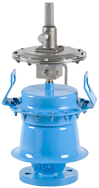
The function of safety valves differs depending on the load or main type of the valve. The main types of safety valves are spring-loaded, weight-loaded and controlled safety valves.
Regardless of the type or load, safety valves are set to a specific set pressure at which the medium is discharged in a controlled manner, thus preventing overpressure of the equipment. In dependence of several parameters such as the contained medium, the set pressure is individual for each safety application.
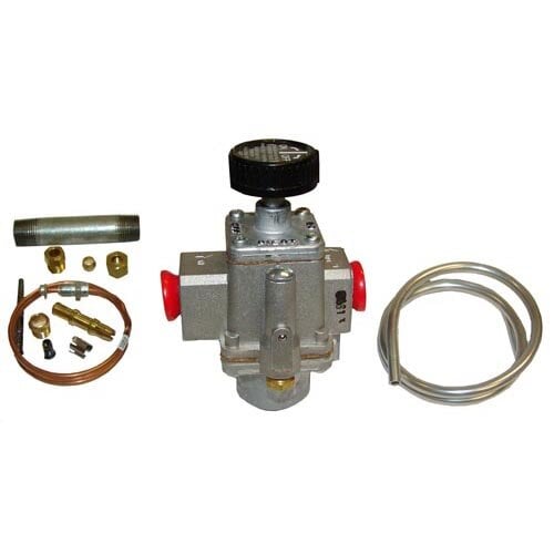
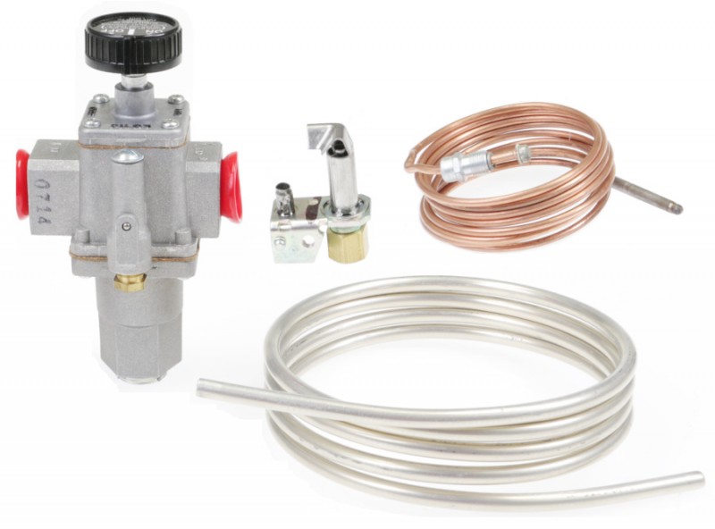
RSTC210-600 - 210°F to 600°F - Robert-Shaw thermostat gas control, temperature control range of 210°F to600°F.Includes: thermocouple, pilot light, spark ignitor, temperature probe, and a 3/8"ID gas hose.
We have high quality Robert-Shaw thermostat gas controls which are ideal for smokers, smokehouses, deep fryers, hog roasters, pig cookers, and many other set-temperature control range applications.These thermostat gas control units are all-in-one assemblies which do not require electricity to operate. They have a built-in safety so that if the pilot light extinguishes, the gas to both the pilot and the burner(s) will be shut off within 20-30 seconds. Thermostat gas control unitscome with thermocouple, pilot light with tubing, piezo spark-ignitor to light the pilot, a temperature probe, and a 3/8” ID outlet gas hose. These pieces are all 5"-6’ in length. Thermostat gas control units will turn the burner on and off based upon the set temperature control range. Theycan be used with low pressure propane or natural gas; maximum inlet pressure is 0.5 psi.
In order to ensure that the maximum allowable accumulation pressure of any system or apparatus protected by a safety valve is never exceeded, careful consideration of the safety valve’s position in the system has to be made. As there is such a wide range of applications, there is no absolute rule as to where the valve should be positioned and therefore, every application needs to be treated separately.
A common steam application for a safety valve is to protect process equipment supplied from a pressure reducing station. Two possible arrangements are shown in Figure 9.3.3.
The safety valve can be fitted within the pressure reducing station itself, that is, before the downstream stop valve, as in Figure 9.3.3 (a), or further downstream, nearer the apparatus as in Figure 9.3.3 (b). Fitting the safety valve before the downstream stop valve has the following advantages:
• The safety valve can be tested in-line by shutting down the downstream stop valve without the chance of downstream apparatus being over pressurised, should the safety valve fail under test.
• When setting the PRV under no-load conditions, the operation of the safety valve can be observed, as this condition is most likely to cause ‘simmer’. If this should occur, the PRV pressure can be adjusted to below the safety valve reseat pressure.
Indeed, a separate safety valve may have to be fitted on the inlet to each downstream piece of apparatus, when the PRV supplies several such pieces of apparatus.
• If supplying one piece of apparatus, which has a MAWP pressure less than the PRV supply pressure, the apparatus must be fitted with a safety valve, preferably close-coupled to its steam inlet connection.
• If a PRV is supplying more than one apparatus and the MAWP of any item is less than the PRV supply pressure, either the PRV station must be fitted with a safety valve set at the lowest possible MAWP of the connected apparatus, or each item of affected apparatus must be fitted with a safety valve.
• The safety valve must be located so that the pressure cannot accumulate in the apparatus viaanother route, for example, from a separate steam line or a bypass line.
It could be argued that every installation deserves special consideration when it comes to safety, but the following applications and situations are a little unusual and worth considering:
• Fire - Any pressure vessel should be protected from overpressure in the event of fire. Although a safety valve mounted for operational protection may also offer protection under fire conditions,such cases require special consideration, which is beyond the scope of this text.
• Exothermic applications - These must be fitted with a safety valve close-coupled to the apparatus steam inlet or the body direct. No alternative applies.
• Safety valves used as warning devices - Sometimes, safety valves are fitted to systems as warning devices. They are not required to relieve fault loads but to warn of pressures increasing above normal working pressures for operational reasons only. In these instances, safety valves are set at the warning pressure and only need to be of minimum size. If there is any danger of systems fitted with such a safety valve exceeding their maximum allowable working pressure, they must be protected by additional safety valves in the usual way.
In order to illustrate the importance of the positioning of a safety valve, consider an automatic pump trap (see Block 14) used to remove condensate from a heating vessel. The automatic pump trap (APT), incorporates a mechanical type pump, which uses the motive force of steam to pump the condensate through the return system. The position of the safety valve will depend on the MAWP of the APT and its required motive inlet pressure.
This arrangement is suitable if the pump-trap motive pressure is less than 1.6 bar g (safety valve set pressure of 2 bar g less 0.3 bar blowdown and a 0.1 bar shut-off margin). Since the MAWP of both the APT and the vessel are greater than the safety valve set pressure, a single safety valve would provide suitable protection for the system.
Here, two separate PRV stations are used each with its own safety valve. If the APT internals failed and steam at 4 bar g passed through the APT and into the vessel, safety valve ‘A’ would relieve this pressure and protect the vessel. Safety valve ‘B’ would not lift as the pressure in the APT is still acceptable and below its set pressure.
It should be noted that safety valve ‘A’ is positioned on the downstream side of the temperature control valve; this is done for both safety and operational reasons:
Operation - There is less chance of safety valve ‘A’ simmering during operation in this position,as the pressure is typically lower after the control valve than before it.
Also, note that if the MAWP of the pump-trap were greater than the pressure upstream of PRV ‘A’, it would be permissible to omit safety valve ‘B’ from the system, but safety valve ‘A’ must be sized to take into account the total fault flow through PRV ‘B’ as well as through PRV ‘A’.
A pharmaceutical factory has twelve jacketed pans on the same production floor, all rated with the same MAWP. Where would the safety valve be positioned?
One solution would be to install a safety valve on the inlet to each pan (Figure 9.3.6). In this instance, each safety valve would have to be sized to pass the entire load, in case the PRV failed open whilst the other eleven pans were shut down.
If additional apparatus with a lower MAWP than the pans (for example, a shell and tube heat exchanger) were to be included in the system, it would be necessary to fit an additional safety valve. This safety valve would be set to an appropriate lower set pressure and sized to pass the fault flow through the temperature control valve (see Figure 9.3.8).

The first thing I will talk about is the pilot safety circuit. We need three things for combustion, air + fuel + heat. The air is supplied from the venting section, and the fuel from the gas piping section. The heat comes in the form of a pilot light, intermittent ignition device, direct spark ignition, or hot surface igniter. As I said before, in this article we will discuss standing pilot lights only.
Let’s go back and take a look at how we used to light pilots; then we’ll talk about the progression of safety devices and the state of technology today.
Development of the Standing PilotOn the old stoves, people used to turn on the gas and light the main burner with a match. As time went on, someone invented the pilot light. The pilot always stayed lit, and when the main burner was turned on, this component ignited it — nice and simple. But what happened if the pilot went out?
A small amount of gas was released to the atmosphere from the pilot burner, and when you went to light the stove, you realized the pilot was out because the stove wouldn’t light. You relit the pilot and you were set.
Now let’s apply this to a boiler. The original gas boilers had what we called wild pilots. There were two gas cocks on the old boilers, an “A” cock and a “B” cock. The “A” cock ran full size to the main gas valve and the “B” cock ran off a 1/8-in. tapping on the “A” cock. The outlet side was a 1/4-in. compression fitting.
From this fitting, 1/4-in. aluminum tubing ran to a pilot assembly. The pilot assembly sat above the main burner, and when the gas valve opened, the pilot lit the main burner. This was known as a “Wild Pilot.” There was no pilot safety control, and if the pilot went out, the main gas would still turn on when there was a call for heat.
The Safety SwitchOnce this problem was recognized, the next step was the development of the electric pilot safety switch. With this device, a thermocouple was put in the pilot flame. The flame should cover 3/8 to 1/2-in. of the thermocouple tip.
The thermocouple is a device made of two strips or wires of dissimilar materials. (See photo.) They are welded together at one end; this is called the hot junction. The pilot flame then heats the hot junction, generating a dc voltage on the other end of the two strips or wires. This is called a thermoelectric reaction.
The output of a single thermocouple is 20 to 30 millivolts dc (1,000 millivolts = 1 V). The voltage at the cold junction energizes an electromagnet, which closes a circuit on the electric pilot safety switch. The way it works is, you open the “B” cock and light the pilot. There is a button, usually red, on the pilot safety switch. You hold it down for 30 sec, which gives the thermocouple a chance to heat up and send the necessary voltage to the electromagnet to close the circuit. If the pilot goes out, the circuit opens.
This switch would get wired in series with the other safety and limit controls on the gas valve; nice and simple, no pilot, no main gas. Don’t forget, back in the old days all the gas valve was, was an electric solenoid valve.
Most valves you run into now are combination gas valves. The solenoid valve, regulator, and pilot safety are all built into one valve. On a standing pilot model we still use a thermocouple, but in a different way. The pilot valve is also built into the combination gas valve, so there’s no more “B” cock.
To light the pilot, you hold down the button on the gas valve to start the flow of gas to the pilot burner. By holding the button down, you are allowing gas into the valve and, at the same time, blocking the flow of gas to the main burner outlet port while allowing it to flow to the pilot burner through a pilot tube coming from the gas valve body. You light the pilot and hold the button down for 30 sec, and when the thermocouple sends the voltage to the gas valve, an electromagnet holds the main safety shutoff in the open position. In this position, pilot gas will always flow and main gas will flow on a call for heat. If the pilot goes out, no gas will flow into the valve.
The only difference between the pilot safety switch and the combination gas valve is that the pilot safety switch is shutting the gas off electrically, and the thermocouple in the gas valve is shutting the gas off mechanically.
Lock Out TestA properly operating safety system should lock out within 3 min of pilot outage. This test should be performed after gas pressure has been adjusted to manufacturer specifications.
Shut the gas to the appliance using the gas cock. After 3 min, turn up the thermostat to call for heat and turn on the gas; no gas should flow to the main burners or pilot burners. If gas is flowing, you must replace the gas valve. If you replace the pilot assembly, you should also do a turndown test.
It is an ANSI requirement that the pilot flame lights the main burner within 4 sec of gas reaching the main burner. This is done with the pilot gas at the minimum necessary to hold the pilot valve open.
2.Locate the pilot adjusting screw and start turning it clockwise until you notice the pilot flame start to decrease. Turn the screw one-quarter turn clockwise. Wait 1 min and turn clockwise. Keep doing this until the pilot safety circuit drops out, shutting the pilot.
4.Now turn up the thermostat to call for heat and turn the gas cock back to the “on” position. The main burners should ignite smoothly without any rollout within 4 sec. If not, relocate the pilot burner and repeat steps 1 through 4.
Let’s Go On a Service CallYou get a call from Mrs. Jones, who has no heat. You look at the boiler and find that the pilot light is out. The heating unit (boiler or furnace) has a standing pilot with a thermocouple.
The first step is to make sure there is gas. Shut the gas cock at the appliance and open a union or drip cap. Turn on the gas cock. If there is gas, shut the gas cock and retighten the gas union or drip cap.
The pilot will not light. Remove the pilot tube at the gas valve and depress the button. If gas is present at the gas valve and not at the pilot, check the pilot tube and pilot assembly orifice for blockages; clean or replace as necessary.
The pilot stays lit.Check the thermocouple for lint or pet hair; clean if necessary. Check the gas pressure at the inlet and outlet of the gas valve with a manometer. It should be within the parameters set by the manufacturer (which can be found on the rating plate or in the installation and operating manual). If the gas pressure is good, turn on other appliances; does pressure drop? If yes, check line sizing. If no, check the pilot flame; is it covering 3/8 to 1/2 in. of the thermocouple tip? If not, adjust. Check the condition of the draft diverter. If damaged, replace it.
If all the above items are within spec, check the thermocouple with a thermocouple tester or a millivolt meter. If the readings are not within the manufacturer’s specified range, replace the thermocouple. If it’s within the manufacturer’s specified range, replace the pilot safety unit or combination gas valve.
Note:When replacing a pilot safety unit or a combination gas valve, always replace the thermocouple. If you do not have a thermocouple tester or millivolt meter, replace the thermocouple; if the pilot still will not stay lit, replace the pilot safety unit or combination gas valve.
This article was excerpted from “The Complete Guide to Residential Gas Heating” by Richard Bruno, an instructor in Nassau County BOCES, Nassau County, NY, and at the Suffolk County BOCES, Suffolk County, NY. Among his professional affiliations, he is a member of the National Old Timers Association of the Oil Heat Industry, and a Long Island Lighting Co. Contractor Advisory Committee Member. He can be reached at 718-668-0180.


 8613371530291