
gas regulator safety valve free sample
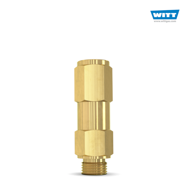
WITT is a manufacturer of Pressure relief valvesor Safety relief valves for technical gases. They are designed to protect against overpressure by discharging pressurized gases and vapors from pipelines, pressure vessels and plant components. Safety relief valves (SRV) are often the last line of defense against explosion – and such an explosion could be fatal. Other common names for safety relief valves are pressure relief valve (PRV), safety valve, pressure safety valve, overpressure valve, relief valve or blow-off valve.
WITT safety valves are very precise. They are individually preset to open at a predetermined pressure within the range 0.07 to 652 Psi. Their small size and orientation-independent installation allow a wide range of connection options. WITT relief valves also stand out due to their high blow-off flow rates of up to 970m³/h. They can be used within a temperature range of -76° F to +518°F and even with very low pressures.
For maximum safety, WITT undertakes 100 % testing of each safety relief valve before it is delivered. In addition, WITT offers individual testing of eachsafety valveby the TÜV, with their certificate as proof of the correct set pressure.
WITTsafety relief valvesare direct-acting, spring-loaded valves. When the preset opening pressure is reached, a spring-loaded element in the valve gives way and opens, and the pressure is relieved. Once the pressures are equalized, the valve closes automatically and can be reactivated any time the pressure rises again. Depending on the application and the nature of the gas, the safety relief valvescan either discharge to atmosphere, or via a connected blow-off line. The opening pressure of the safety valves is preset by WITT at the factory according to the customer’s requirements.
Safety relief valvesare used in numerous industries and industrial applications where, for example, gases pass through pipelines or where special process vessels have to be filled with gas at a certain pressure.
For most industrial applications using technical gases, brass is usually the standard material of construction of thesafety relief valvebody/housing. For the use of pressure relief valves with aggressive and corrosive gases, the housings are made of high-quality stainless steel (1.4541/AISI 321, 1.4404/AISI 316L, 1.4305/AISI 303 or 1.4571/AISI 316Ti). The use of aluminium as a housing material is also possible.
Depending on the type of gas used and individual customer requirements, various sealing materials and elastomers are available to ensure the safety of your systems under even the most difficult conditions.
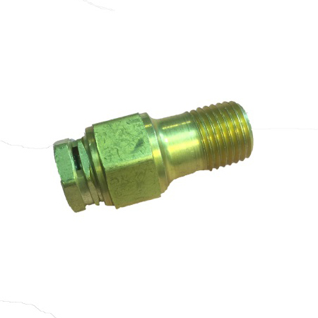
WITT pressure relief valves are available with different connections. In addition to the standard versions with the usual internal or external threads, special versions with KF or CF flanges, VCR or UNF threads can also be ordered. Special adapters for connecting the safety relief valve to a blow-off line are also available.

The primary purpose of a safety valve is to protect life, property and the environment. Safety valves are designed to open and release excess pressure from vessels or equipment and then close again.
The function of safety valves differs depending on the load or main type of the valve. The main types of safety valves are spring-loaded, weight-loaded and controlled safety valves.
Regardless of the type or load, safety valves are set to a specific set pressure at which the medium is discharged in a controlled manner, thus preventing overpressure of the equipment. In dependence of several parameters such as the contained medium, the set pressure is individual for each safety application.
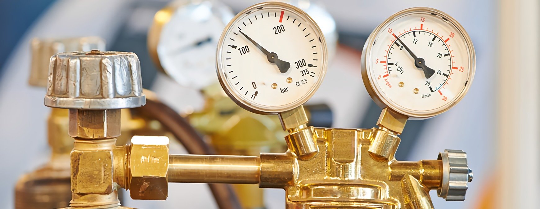
Pressure regulators reduce the high pressures of the stored gas in the cylinder to lower pressures that can be safely used in an operating system. Proper regulator selection is critical for both safety and effectiveness of operating systems. Regulators are designed to control pressure; they do not measure or control flow, unless equipped with devices such as a flow meter specifically designed for such purposes.
Regulator connections to cylinder valves must be completely free of dirt, dust, oil, and grease. "Crack" the valve slowly (by opening the valve slightly and then reclosing it) before attaching the regulator in order to blow out dust and debris from the opening. Note: Cylinders containing highly toxic gases should not be "cracked".
Regulators are attached to the cylinder, or manifold, at the inlet connection. This connection should be tested for leaks with a non-petroleum based product. Note that many soaps contain petroleum! The connection is marked with a Compressed Gas Association (CGA) number and will be left-hand or right-hand threaded to match the nut or fitting. This prevents a piece of incompatible gas equipment from being connected to the wrong gas supply.
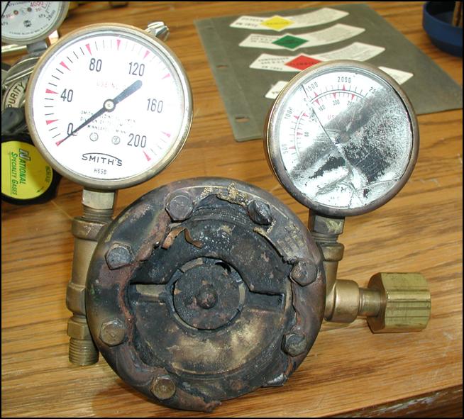
Never use damaged or defective equipment. In fact, it"s best not to use a regulator that you do not know the history of - it may have been misused or repaired by an unauthorized person. Refer any problems or defects to the manufacturer for recommendations and authorized repair.
Opening a Regulator - Stand on the valve side of the cylinder at arms length so you do not have to reach in front of the regulator face. Turn your head away from the regulator and open the valve, turning counter clockwise, to blow out dust and debris, and then reclose the valve.
Changing a Regulator - Close the valve and drain the regulator by backing out the adjusting screw. Disconnect the regulator, making sure not to touch the nut and gland areas. Connect the regulator to the new cylinder.
Closing a Regulator - Turn the valve clockwise to close the valve. Drain the regulator by turning (opening) the adjusting crew to release any gas. Reclose the adjusting screw.
Recommendation: To provide easier access and additional safety, purchase wall-mounted regulators which connect to the supply cylinder by hose. This will reduce the handling of the regulator and reduce the likelihood of damage.
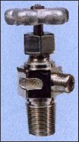
Diaphragm Valve - This valve uses a two piece stem separated by non-perforated diaphragms. These diaphragms prevent leakage along the valve stem. The lower part of the stem is encased in a spring, which forces the stem away from the seat whent eh valve is opened. The upper stem is threaded into the diaphragm retainer nut. When the handwheel is rotated to the closed position, the upper stem pushes on the diaphragms, which deflect downward, forcing the lower stem against the valve seat. Advantages of this type of valve are that they provide superior leak integrity and have no threads or lubricants in the gas stream to generate particles or contaminants. This type of valve is required for mos
Compressed gas cylinders shall have a pressure relief device installed to prevent the rupture of a normally pressurized cylinder when inadvertently exposed to fire of high temperatures. There are four basic types of pressure relief devices:
Rupture Disk Devices - A flat disk typically made of metal that is designed to burst at a predetermined pressure to permit the release of gas. The pressure rating of the disk is typically stamped onto the face of the device. Examples of gases using this type of device include compressed air, argon, helium, nitrogen, and oxygen.
Fusible Plug Devices - A plug made of fusible metal designed to yield or melt at low temperatures (usually 165 or 212 degrees F). The temperature rating of the fusible metal is stamped onto the face of the device. An examples of a gas that uses this type of device is acetylene.
Combination Ruture Disks/Fusible Plug Devices - A rupture disk backed by a fusible plug. In the event of a fire, the fusible metal melts and cylinder overpressure is relieved by the bursting of the disk. The burst pressure of the disk and the melting point of the plug will be marked with the ratings. Medical grade gas cylinders typically have this type of pressure relief device.
Pressure Relief Valves - A spring-loaded valve opens when the cylinder pressure exceeds the pressure setting of the spring to discharge contents. Once the cylinder pressure decreases to the valve"s pressure setting, the valve will normally reseat without leakage.
CountryUnited StatesAfghanistanÅland IslandsAlbaniaAlgeriaAmerican SamoaAndorraAngolaAnguillaAntarcticaAntigua and BarbudaArgentinaArmeniaArubaAustraliaAustriaAzerbaijanBahamasBahrainBangladeshBarbadosBelarusBelgiumBelizeBeninBermudaBhutanBoliviaBonaire, Sint Eustatius and SabaBosnia and HerzegovinaBotswanaBouvet IslandBrazilBritish Indian Ocean TerritoryBrunei DarrussalamBulgariaBurkina FasoBurundiCambodiaCameroonCanadaCape VerdeCayman IslandsCentral African RepublicChadChileChinaChristmas IslandCocos IslandsColombiaComorosCongo, Democratic Republic of theCongo, Republic of theCook IslandsCosta RicaCôte d"IvoireCroatiaCubaCuraçaoCyprusCzech RepublicDenmarkDjiboutiDominicaDominican RepublicEcuadorEgyptEl SalvadorEquatorial GuineaEritreaEstoniaEswatini (Swaziland)EthiopiaFalkland IslandsFaroe IslandsFijiFinlandFranceFrench GuianaFrench PolynesiaFrench Southern TerritoriesGabonGambiaGeorgiaGermanyGhanaGibraltarGreeceGreenlandGrenadaGuadeloupeGuamGuatemalaGuernseyGuineaGuinea-BissauGuyanaHaitiHeard and McDonald IslandsHoly SeeHondurasHong KongHungaryIcelandIndiaIndonesiaIranIraqIrelandIsle of ManIsraelItalyJamaicaJapanJerseyJordanKazakhstanKenyaKiribatiKuwaitKyrgyzstanLao People"s Democratic RepublicLatviaLebanonLesothoLiberiaLibyaLiechtensteinLithuaniaLuxembourgMacauMacedoniaMadagascarMalawiMalaysiaMaldivesMaliMaltaMarshall IslandsMartiniqueMauritaniaMauritiusMayotteMexicoMicronesiaMoldovaMonacoMongoliaMontenegroMontserratMoroccoMozambiqueMyanmarNamibiaNauruNepalNetherlandsNew CaledoniaNew ZealandNicaraguaNigerNigeriaNiueNorfolk IslandNorth KoreaNorthern Mariana IslandsNorwayOmanPakistanPalauPalestine, State ofPanamaPapua New GuineaParaguayPeruPhilippinesPitcairnPolandPortugalPuerto RicoQatarRéunionRomaniaRussiaRwandaSaint BarthélemySaint HelenaSaint Kitts and NevisSaint LuciaSaint MartinSaint Pierre and MiquelonSaint Vincent and the GrenadinesSamoaSan MarinoSao Tome and PrincipeSaudi ArabiaSenegalSerbiaSeychellesSierra LeoneSingaporeSint MaartenSlovakiaSloveniaSolomon IslandsSomaliaSouth AfricaSouth GeorgiaSouth KoreaSouth SudanSpainSri LankaSudanSurinameSvalbard and Jan Mayen IslandsSwedenSwitzerlandSyriaTaiwanTajikistanTanzaniaThailandTimor-LesteTogoTokelauTongaTrinidad and TobagoTunisiaTurkeyTurkmenistanTurks and Caicos IslandsTuvaluUgandaUkraineUnited Arab EmiratesUnited KingdomUruguayUS Minor Outlying IslandsUzbekistanVanuatuVenezuelaVietnamVirgin Islands, BritishVirgin Islands, U.S.Wallis and FutunaWestern SaharaYemenZambiaZimbabwe

Single stage pressure regulators for cylinder through point of use applications. The inlet pressures range from vacuum to 4,500 psig (310 bar) while outlet pressures range from absolute to 500 psig (34 bar). Flow ratings go from a few sccm up to 5,000 slpm of N2 with line sizes from ¼ inch through 1 inch.
Compact single stage pressure regulators for applications where space is limited, such as inside a process tool. Available in IGS configurations, C and W seal, in addition to conventional face seal. Absolute through 100 psig (7 bar) pressure delivery range with flow rates from a few sccm to 100 slpm.
Single stage pressure regulators for higher pressures – up to 10,000 psig (690 bar) inlet and outlet. These primarily piston sensed devices are the regulators of choice for delivery pressures above 300 psig (20 bar) and line sizes from ¼ to ½ inch.
Pressure regulators which do not have a wetted poppet spring. Four models are available ranging from a mini regulator, medium flow cylinder regulator to a line regulator which can deliver 300 slpm of N2.
Pressure regulators which provide two step pressure reduction by having two single stage regulators combined in a common body. Two models are available which meet most requirements for two stage regulators. A two stage regulator is an integrated unit as opposed to two separate single stage regulators in series which also provide two stage regulation.
A back pressure regulator is basically a precision pressure relief device which is used to control a maximum gas system pressure. A single model is available.
A broad range of pneumatically actuated diaphragm valves are available with operating pressures up to 4,500 psig (310 bar) with a mix of normally closed (NC) and normally open (NO) configurations.
A broad range of manual valves is available with pressure ratings up to 4,500 psig (310 bar) with line sizes to 1 inch. The wide variety of actuation types combined with lock out / tag out (LOTO) options, sizes and pressure ratings provide the valve for most requirements.
A variety of venturi models provide vacuum in either discrete devices or integrated modules which combine vacuum venturi with N2 shut off valve and check valve in one compact unit.
A wide range of flow switches is available for detecting excess flow. An online calculator enables one to easily select a switch for a given gas application.
From laboratory benches to busy manufacturing facilities and commercial fueling stations, industrial pressure regulators play a crucial role in ensuring fluids are contained and transferred under optimal pressures. If pressure cannot be properly controlled in these applications, test results may be invalidated, processes may be disrupted, equipment may be damaged, and personnel may be put at risk. You need to know the regulators in your system will consistently and accurately maintain pressure levels over extended operating lifespans—all without requiring frequent maintenance, repair, or replacement.
Swagelok pressure regulators provide the consistent, accurate, and lasting performance needed to operate fluid systems safely, reliably, and cost-effectively.
Swagelok has advisors on fluid systems located at authorized sales and service centers around the world to provide local support in choosing between a spring-loaded, a dome-loaded, or one of the many other available regulator configurations. These advisors can also help diagnose regulator problems and customize and build fluid systems that include regulators such as a gas distribution system.

I believe that on almost every boiler project that I have been involved in over the past few decades, there always seems to be confusion regarding the venting requirements for safety relief valves and gas regulator common venting. Below, I have referenced the codes that apply to these topics, in addition to some examples.
Where there is more than one gas pressure regulator at a location, each gas pressure regulator shall have a separate vent to the outdoors at a safe point of discharge as determined by the authority having jurisdiction. If approved by the authority having jurisdiction, the vent lines may be manifolded in accordance with accepted engineering practices [see (b) and (c) below] to minimize backpressure in the event of diaphragm failure. (b) Atmospheric vent lines, when manifolded shall be connected to a common atmospheric vent line having a cross sectional area not less than the area of the largest vent line plus 50% of the area of the additional vent lines. (c) Atmospheric vent lines shall not be connected to any common manifolded gas vent, bleed or relief lines.
(C) It is recommended that individual discharge lines be used, but if two or more reliefs are combined, the discharge piping shall be designed with sufficient flow area to prevent blowout of steam or other fluids. Sectional areas of a discharge pipe shall not be less than the full area of the valve outlets discharging thereinto and the discharge pipe shall be as short and straight as possible and so arranged as to avoid undue stresses on the valve or valves.
After reviewing the codes detailed above, you can see that contrary to popular belief, it is possible to incorporate a common vent manifold for boiler safety relief valves, and also for gas valves. Below are some examples.
Manifold gas vent lines common (1 ¼” each boiler x (4) Units (1.84” + .92” +.92” + .92” = 4.6”) therefore, a 2 ½” manifold would be recommended (cross sectional area of 4.9”)
Manifolded relief valves (I don’t interpret this code to limit only the boilers to this vent line but would include DA and pressure reducing stations)
Boilers (2) 2 ½” relief valves per boiler (4.9” cross sectional area each) x (4) Boilers (39.2” total) therefore, an 8” manifold would be recommended (50.2” cross sectional area).
The same methodology can be used when venting pressure reducing stations and deaerators per the referenced code with proper Department approval. Remember, the purpose of a Drip Pan Elbow is to provide a suitable unrestricted, self-draining outlet in addition to isolating Safety Relief Valves (SRV’s) from discharge piping stresses. The Safety Relief Valve discharge size increases to isolate the drip pan elbow from backpressure. Steam won’t escape from the drip pan elbow if the vent line is sized appropriately.
If you run into a situation where common venting is required for safety relief valve(s), gas regulators, or pressure reducing stations, please feel free to contact Fluid Handling, Inc. in Menomonee Falls, WI and we will work with you to determine the appropriate solution.
Pressure regulators are available in two types: relieving and non-relieving. Both can give the maximum volume of flow needed while keeping outlet pressure constant. The difference between relieving and non-relieving regulators depends on whether they self-release or trap excess pressure. At Air Logic, we offer both relieving and non-relieving pressure regulators that can be either preset or adjustable.
A relieving regulator releases excess pressure through a relief valve, a hole in the middle of the diaphragm. When air pressure exceeds the acceptable limit of a system, the relieving regulator opens a vent to allow the air to escape. A hissing sound usually indicates the release of air. There is no need to add an extra relief valve to the flow system since the relieving regulator performs this function on its own.
A non-relieving regulator restricts airflow once it exceeds the setpoint. There’s no vent path in a non-relieving regulator so the gas stays in the system. These regulators require extra care because they can become dangerous if excess pressure builds up without being released. In a closed system, it is important to have a relief valve downstream. Alternatively, an open system design should be implemented downstream of the regulator to prevent the build-up of excessive pressure.
Non-relieving regulators are most beneficial when dealing with hazardous or expensive gases. By trapping these gases for safe or controlled release, operators ensure the safety and efficiency of the entire facility.
Knowing the difference between a relieving and non-relieving regulator will help you make an informed decision for your application. Air Logic produces a vast selection of pneumatic equipment and control components, including relieving and non-relieving regulators.
Our Modular Subminiature Relieving Regulator is designed to regulate pressure accurately with minimal consumption. For non-relieving regulator applications, our Modular Subminiature Non-Relieving Regulator provides accurate pressure regulation without pressure bleeding.
Pressure Regulators are found in many common home and industrial applications. For example, pressure regulators are used in gas grills to regulate propane, in home heating furnaces to regulate natural gases, in medical and dental equipment to regulate oxygen and anesthesia gases, in pneumatic automation systems to regulate compressed air, in engines to regulate fuel and in fuel cells to regulate hydrogen. As this partial list demonstrates there are numerous applications for regulators yet, in each of them, the pressure regulator provides the same function. Pressure regulators reduce a supply (or inlet) pressure to a lower outlet pressure and work to maintain this outlet pressure despite fluctuations in the inlet pressure. The reduction of the inlet pressure to a lower outlet pressure is the key characteristic of pressure regulators.
When choosing a pressure regulator many factors must be considered. Important considerations include: operating pressure ranges for the inlet and outlet, flow requirements, the fluid (Is it a gas, a liquid, toxic, or flammable?), expected operating temperature range, material selection for the regulator components including seals, as well as size and weight constraints.
A wide range of materials are available to handle various fluids and operating environments. Common regulator component materials include brass, plastic, and aluminum. Various grades of stainless steel (such as 303, 304, and 316) are available too. Springs used inside the regulator are typically made of music wire (carbon steel) or stainless steel.
The chemical properties of the fluid should be considered before determining the best materials for your application. Each fluid will have its own unique characteristics so care must be taken to select the appropriate body and seal materials that will come in contact with fluid. The parts of the regulator in contact with the fluid are known as the “wetted” components.
It is also important to determine if the fluid is flammable, toxic, explosive, or hazardous in nature. A non-relieving regulator is preferred for use with hazardous, explosive, or expensive gases because the design does not vent excessive downstream pressure into the atmosphere. In contrast to a non-relieving regulator, a relieving (also known as self-relieving) regulator is designed to vent excess downstream pressure to atmosphere. Typically there is a vent hole in the side of the regulator body for this purpose. In some special designs, the vent port can be threaded and any excess pressure can be vented from the regulator body through tubing and exhausted in a safe area. If this type of design is selected the excess fluid should be vented appropriately and in accordance to all safety regulations.
The materials selected for the pressure regulator not only need to be compatible with the fluid but also must be able to function properly at the expected operating temperature. The primary concern is whether or not the elastomer chosen will function properly throughout the expected temperature range. Additionally, the operating temperature may affect flow capacity and/or the spring rate in extreme applications.
The inlet and outlet pressures are important factors to consider before choosing the best regulator. Important questions to answer are: What is the range of fluctuation in the inlet pressure? What is the required outlet pressure? What is the allowable variation in outlet pressure?
In many high technology applications space is limited and weight is a factor. Some manufactures specialize in miniature components and should be consulted. Material selection, particularly the regulator body components, will impact weight. Also carefully consider the port (thread) sizes, adjustment styles, and mounting options as these will influence size and weight.
In operation, the reference force generated by the spring opens the valve. The opening of the valve applies pressure to the sensing element which in turn closes the valve until it is open just enough to maintain the set pressure. The simplified schematic “Pressure Regulator Schematic” illustrates this force balance arrangement. (see below)
Most commonly, regulators employ a spring loaded “poppet” valve as a restrictive element. The poppet includes an elastomeric seal or, in some high pressure designs a thermoplastic seal, which is configured to make a seal on a valve seat. When the spring force moves the seal away from the valve seat, fluid is allowed to flow from the inlet of the regulator to the outlet. As the outlet pressure rises, the force generated by the sensing element resists the force of the spring and the valve is closed. These two forces reach a balance point at the set point of the pressure regulator. When the downstream pressure drops below the set-point, the spring pushes the poppet away from the valve seat and additional fluid is allowed to flow from the inlet to the outlet until the force balance is restored.
Piston style designs are often used when higher outlet pressures are required, when ruggedness is a concern or when the outlet pressure does not have to be held to a tight tolerance. Piston designs tend to be sluggish, as compared to diaphragm designs, because of the friction between the piston seal and the regulator body.
In low pressure applications, or when high accuracy is required, the diaphragm style is preferred. Diaphragm regulators employ a thin disc shaped element which is used to sense pressure changes. They are usually made of an elastomer, however, thin convoluted metal is used in special applications. Diaphragms essentially eliminate the friction inherent with piston style designs. Additionally, for a particular regulator size, it is often possible to provide a greater sensing area with a diaphragm design than would be feasible if a piston style design was employed.
The reference force element is usually a mechanical spring. This spring exerts a force on the sensing element and acts to open the valve. Most regulators are designed with an adjustment which allows the user to adjust the outlet pressure set-point by changing the force exerted by the reference spring.
The accuracy of a pressure regulator is determined by charting outlet pressure versus flow rate. The resulting graph shows the drop in outlet pressure as the flow rate increases. This phenomenon is known as droop. Pressure regulator accuracy is defined as how much droop the device exhibits over a range of flows; less droop equals greater accuracy. The pressure versus flow curves provided in the graph “Direct Acting Pressure Regulator Operating Map”, indicates the useful regulating capacity of the regulator. When selecting a regulator, engineers should examine pressure versus flow curves to ensure the regulator can meet the performance requirements necessary for the proposed application.
The term “droop” is used to describe the drop in the outlet pressure, below the original set-point, as flow increases. Droop can also be caused by significant changes in the inlet pressure (from the value when the regulator output was set). As the inlet pressure rises from the initial setting, the outlet pressure falls. Conversely, as the inlet pressure falls, the outlet pressure rises. As seen in the graph “Direct Acting Pressure Regulator Operating Map”, this effect is important to a user because it shows the useful regulating capacity of a regulator.
Increasing the valve orifice can increase the flow capacity of the regulator. This may be beneficial if your design can accommodate a bigger regulator however be careful not to over specify. A regulator with an oversized valve, for the conditions of the intended application, will result in a greater sensitivity to fluctuating inlet pressures, and may cause excessive droop.
Hysteresis can occur in mechanical systems, such as pressure regulators, due to friction forces caused by springs and seals. Take a look at the graph and you will notice, for a given flow rate, that the outlet pressure will be higher with decreasing flow than it will be with increasing flow.
Single-stage regulators are an excellent choice for relatively small reductions in pressure. For example, the air compressors used in most factories generate maximum pressures in the 100 to 150 psi range. This pressure is piped through the factory but is often reduced with a single-stage regulator to lower pressures (10 psi, 50 psi, 80 psi etc.) to operate automated machinery, test stands, machine tools, leak test equipment, linear actuators, and other devices. Single stage pressure regulators typically do not perform well with large swings in inlet pressure and/or flow rates.
A two-stage pressure regulator is ideal for applications with large variations in the flow rate, significant fluctuations in the inlet pressure, or decreasing inlet pressure such as occurs with gas supplied from a small storage tank or gas cylinder.
With most single-stage regulator regulators, except those that use a pressure compensated design, a large drop in inlet pressure will cause a slight increase in outlet pressure. This happens because the forces acting on the valve change, due to the large drop in pressure, from when the outlet pressure was initially set. In a two-stage design the second stage will not be subjected to these large changes in inlet pressure, only the slight change from the outlet of the first stage. This arrangement results in a stable outlet pressure from the second stage despite the significant changes in pressure supplied to the first stage.
A three-stage regulator provides a stable outlet pressure similar to a two-stage regulator but with the added ability to handle a significantly higher maximum inlet pressure. For example, the Beswick PRD3HP series three-stage regulator is rated to handle an inlet pressure as high as 3,000 psi and it will provide a stable outlet pressure (in the 0 to 30 psi range) despite changes to the supply pressure. A small and lightweight pressure regulator that can maintain a stable low output pressure despite an inlet pressure that will decrease over time from a high pressure is a critical component in many designs. Examples include portable analytical instruments, hydrogen fuel cells, UAVs, and medical devices powered by high pressure gas supplied from a gas cartridge or storage cylinder.
Now that you have chosen the regulator that best suits your application it is important that the regulator is installed and adjusted properly to insure that it functions as intended.
Most manufacturers recommend the installation of a filter upstream of the regulator (some regulators have a built-in filter) to prevent dirt and particulates from contaminating the valve seat. Operation of a regulator without a filter could result in a leaking to the outlet port if the valve seat is contaminated with dirt or foreign material. Regulated gases should be free from oils, greases, and other contaminants which could foul or damage the valve components or attack the regulator seals. Many users are unaware that gases supplied in cylinders and small gas cartridges can contain traces of oils from the manufacturing process. The presence of oil in the gas is often not apparent to the user and therefore this topic should be discussed with your gas supplier before you select the seal materials for your regulator. Additionally, gasses should be free of excessive moisture. In high flow rate applications, icing of the regulator can occur if moisture is present.
If the pressure regulator will be used with oxygen, be aware that that oxygen requires specialized knowledge for safe system design. Oxygen compatible lubricants must be specified and extra cleaning, to remove traces of petroleum based cutting oils, is typically specified. Make certain that you inform your regulator supplier that you plan to use the regulator in an oxygen application.
Do not connect regulators to a supply source with a maximum pressure greater than the rated inlet pressure of the regulator. Pressure regulators are not intended to be used as shutoff devices. When the regulator is not in use, the supply pressure should be turned off.
Before turning on the supply pressure to the regulator, back off the adjustment control knob to restrict flow through the regulator. Gradually turn on the supply pressure so as not to “shock” the regulator with a sudden rush of pressurized fluid. NOTE: Avoid turning the adjustment screw all the way into the regulator because, in some regulator designs, the full supply pressure will be delivered to the outlet port.
Set the pressure regulator to the desired outlet pressure. If the regulator in non-relieving, it will be easier to adjust the outlet pressure if fluid is flowing rather than “dead ended” (no flow). If the measured outlet pressure exceeds the desired outlet pressure, vent the fluid from the downstream side of the regulator and lower the outlet pressure by turning the adjustment knob. Never vent fluid by loosening fittings, as injury may result.
With a relieving style regulator, excess pressure will be automatically vented to atmosphere from the downstream side of the regulator when the knob is rotated to lower the output setting. For this reason, do not use relieving style regulators with flammable or hazardous fluids. Be sure the excess fluid is vented safely and in accordance with all local, state and federal regulations.
To obtain the desired outlet pressure, make the final adjustments by slowly increasing the pressure from below the desired set point. Setting the pressure from below the desired setting is preferred to setting it from above the desired setting. If you overshoot the set point while setting the pressure regulator, back off the set pressure to a point below the set point. Then, again, gradually increase the pressure to the desired set point.
Cycle the supply pressure on and off several times while monitoring the outlet pressure to confirm the regulator is consistently returning to the set point. Additionally, the outlet pressure should also be cycled on and off to ensure the pressure regulator returns to the desired set point. Repeat the pressure setting sequence if the outlet pressure does not return to the desired setting.
Beswick Engineering specializes in miniature liquid and pneumatic fittings, quick disconnects, valves and regulators. We have a team of degreed Application Engineers ready to assist you with your questions. Custom designs are available upon request. Submit your inquiry on our Contact Us page or click the Live Chat icon in the bottom right of your screen.


 8613371530291