
honeywell safety valve free sample

Gas temperature range of -58F (-50C) to 212F (100C)More powerful with Partial Stroke Test Technology. The Series 8000 Valve can be coupled with MAXON"s PSCheck Partial Stroke Testing technology to ensure maximum uptime without sacrificing safety. The PSCheck technology, when combined with the Series 8000 safety shut-off valve, provides the highest level of safety security that can be SIL 3 certified. The PSCheck was designed to minimize probability of failure on demand by automatically testing valve function without process flow interruption or line shutdown. Click here for more information on MAXON"s Partial Stroke Testing solution with Series 8000 Valves. The Series 8000 Valve is now available with the following enhancements:
MAXON Series 8000 Pneumatic Safety Shut-off Valves combine a unique space-saving design with a maintenance-free bonnet seal and a replaceable actuator for easy installation and smooth, trouble-free operation
The field-replaceable actuator provides easier maintenance and reduced downtime. The actuator can also be rotated around the valve body in 90° incrementsto fit your specific application requirements
The large top-mounted open-shut indicator is visible from all angles for easy proof of valve position. SIL 3 capable design provides easy design for safety instrumented systems in the IEC 61508 and 61511 process. FM, CSA and CE approvals for use as a fuel safety shut-off valve making easy integration with worldwide certifications
MAXON offers MAXON PSCheck partial stroke test technology designed especially for Series 8000 valves, to minimize probability of failure on demand by testing valve function without line shutdown. The combination of MAXON PSCheck and SIL 3 capable Series 8000 valves will help ensure safe, reliable operation of your process
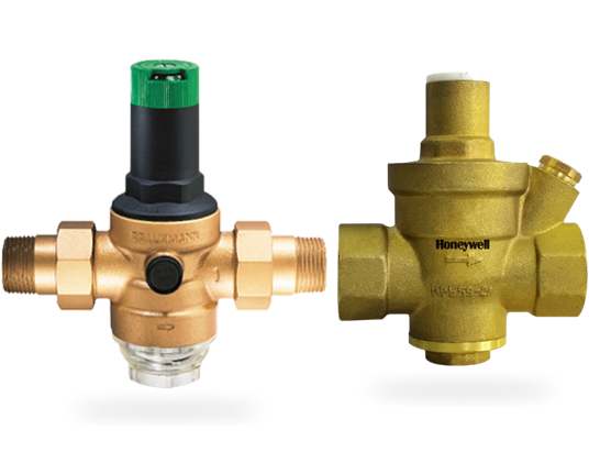
Honeywell’s PRVs have been fitted in millions of buildings thanks to advantages like high quality design, consistent performance and ease of installation. By balancing and optimising inlet pressure, the PRV prevents damage to water systems and consequently to buildings. Since it is not sensitive to dirt and is also resistant to corrosion and scaling, the PRV offers reliable and consistent operations over many years.

*Shipping discount applies to customers without negotiated freight. This offer is not valid for items sent Second Day Air or Next Day Air. To verify freight terms, please contact Magid Glove & Safety at 800-863-1083.
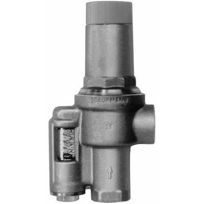
The Resideo Braukmann SV300 Pilot Operated Safety Valve is controlled by the medium flowing through it via a pilot valve. It is preferably installed in branches of supply pipework and protects downstream parts of a system which are at risk from unacceptable excess pressure which can, for example, be caused by pumps. If the inlet pressure to the valve rises up to the set opening pressure, then the valve opens immediately to the maximum flow position. If the pressure falls to the set pressure, then the valve closes slowly to prevent pressure shock loads.

If you have been searching for a safety release valve that you can use to reduce short-term pressure surges successfully and diminish the effects of gas leaks, this is the product for ...
... regulators have safety valves which will slam shut in the event of emergencies, such as the gas reaching too high a pressure level. The valve works to protect any fittings ...
This product has hydraulically actuated class A gas safety valves to EN 161 used for automatic shut-off. It shuts off when unstimulated for gas and air, ...
The S 104 Safety Shut Off valve is mainly used to avoid any damage to components as well as to avoid too high or too low pressure in the gas train. This could cause high financial losses ...
The S50 Safety Shut Off valve is mainly used to avoid any damage to components as well as to avoid too high or too low pressure in the gas train. This could cause high financial losses ...
The S100 Safety Shut Off valve is mainly used to avoid any damage to components as well as to avoid too high or too low pressure in the gas train. This could cause high financial losses ...
... Pressure Safety Valve + Rupture Disk is protected and may be utilized autonomously as essential security gadgets or in conjunction. There are 3 possible combinations. The first combinations ...
It"s a Safety valve in according with Directives ATEX 20K/34/EU. Technical Norm Fire Prevention 41/256 31/10/2019. d.P.R. 10/520 19/03/1955 and subsequent amendments.
130 Series Safety valves are also available as Relief valves. Relief valves, identified by the letter R after the type number, are devices with an operational function, ...
V651 Series safety relief valves are produced as safety and relief type. Safety valves are pressure relief elements used to evacuate excessive pressure ...
PVS type slam shut valves are pilot-operated relief valves in which the opening and the closing of the main plug is controlled by a pilot device which is very ...
This range of spring loaded conventional and balanced safety relief valves is specifically designed for overpressure protection of unfired pressure vessel (ASME Section VIII application). ...
The EMERSON BM7 SERIES is a disk slam-shut valve characterized as automatic isolating elements, which are suitable for installation as safety devices in regulating stations. This device has a high operation ...
... control and regulate the gas, air flow to burners and other combustion devices. HMV is a unique safety valve that can be supplied for the requiremen of handling higher ...
Type 50 is a safety valve for universal use. It can be used for nearly any industrial application, e.g. in shipping and pipeline construction, the chemical and petrochemical industries, ...
The RIEGER Safety valve Type SH prevents excessive pressure in steam and gaseous media in plant components and tanks. The set pressure is generally higher than the operating pressure of the system.
... sewage, gas, glycol, diathermic oil, industrial water, steam and other natural and aggressive media, depending on theresistance of materials usedfor the construction ofthe valve.

Valves are commonly used in conjunction with many appliances for regulating the flow of fluid. For example, gas valves are often incorporated into gas-fired appliances to regulate the flow of gas to a combustion chamber or burner. Examples of such gas-fired appliances may include, but are not limited to, water heaters, furnaces, boilers, fireplace inserts, stoves, ovens, dryers, grills, deep fryers, or any other such device where gas control is desired. In such gas-fired appliances, the gas may be ignited by a pilot flame, electronic ignition source, or other ignition source, causing combustion of the gas at the burner element producing heat for the appliance. In many cases, in response to a control signal from a control device such as a thermostat or other controller, the gas valve may be moved between a closed position, which prevents gas flow, and an open position, which allows gas flow. In some instances, the gas valve may be a modulating gas valve, which allows gas to flow at one or more intermediate flow rates between the fully open position and the fully closed position.
This disclosure relates generally to valves, and more particularly, to gas valve assemblies. In one illustrative but non-limiting example, a valve assembly may include a valve body having an interior and an exterior, a valve or valve sealing member positioned in the valve body, a sensor element (e.g., a magnet or ferrous core) secured relative to the valve sealing member and a sensor (e.g., a magnetic field sensor) positioned outside of the interior of the valve body. The valve sealing member may be movable between an opened position and a closed position, and the sensor element may move with the valve sealing member. The sensor may be configured to detect a position of the valve sealing member and communicate that position to a valve controller.
In some instances, the valve body may have an inlet port and outlet port with a fluid path extending between the inlet port and the outlet port. A first and an optional second valve may be situated between the inlet port and the outlet port, with the second valve, if included, positioned downstream of the first valve. Each valve may be in communication with a valve actuator that may be capable of actuating a respective valve to move. In some cases, the valve assembly may include a first position sensor for detecting a position of the first valve, and a second position sensor for detecting a position of the second valve, where the position sensors may be fluidly isolated from the fluid path of the valve body. The isolated position sensors may be in parallel or series communication with a valve controller, which may also be isolated from the fluid path of the valve body. The valve controller may monitor the positions of valve sealing members through communication with the position sensors.
In some instances, the valve body may have one or more switched signal paths and one or more respective control inputs, where the one or more switched signal paths may communicate with a remote device that is in communication with the valve assembly. Each control input may be configured to set the state of its respective or shared switched signal path to either a first state or a second state. Each control input may be controlled by the valve controller, which may allow the valve controller to control the state of the switched signal paths. The valve controller may set the state of each control input in response to receiving positioning information from the position sensors, and/or in response to other information as desired. In an illustrative example, the valve controller may set the state of a first switched signal path to the first state when a first position sensor senses that the first valve is not in the closed position. Likewise, the valve controller may set the state of a second switched signal path to the first state when a second position sensor senses that the second valve is not in the closed position. Alternatively, or in addition, there may be a single switched signal path and the valve controller may set the state of the single switched signal path to the first state when either or both of the first and second position sensors sense that the first and/or second valve(s), respectively, is/are not in the closed position.
FIG. 3 is a schematic second side view of the illustrative fluid valve assembly of FIG. 1, where the second side view is from a side opposite the first side view;
FIG. 9 is a schematic diagram showing an illustrative fluid valve assembly in communication with a building control system and an appliance control system, where the fluid valve assembly includes a differential pressure sensor connect to a valve controller;
FIG. 10 is a schematic diagram showing an illustrative fluid valve assembly in communication with a building control system and an appliance control system, where the fluid valve assembly includes multiple pressure sensors connected to a valve controller;
FIG. 12 is a schematic diagram showing an illustrative schematic valve control and combustion appliance control, where the controls are connected via a communication link;
FIGS. 14-17 are various illustrative schematic depictions of different methods for sensing a position and/or state of a valve within an illustrative valve assembly.
Gas valves may be added to fluid path systems supplying fuel and/or fluid to appliances (e.g., burners, etc.) or may be used individually or in different systems. In some instances, gas safety shutoff valves may be utilized as automatic redundant valves. Redundancy is achieved, and often times required by regulatory agencies, by placing at least two safety shutoff valves in series. The aforementioned redundant valves may be separate valves fitted together in the field and/or valves located together in a single valve body, these redundant valves are commonly referred to as double-block valves. In accordance with this disclosure, these and other gas valves may be fitted to include sensors and/or switches and/or other mechanical or electronic devices to assist in monitoring and/or analyzing the operation of the gas valve and/or connected appliance. The sensors and/or switches may be of the electromechanical type or the electronic type, or of other types of sensors and/or switches, as desired.
In some cases, a gas valve assembly may be configured to monitor and/or control various operations including, but not limited to, monitoring fluid flow and/or fluid consumption, electronic cycle counting, overpressure diagnostics, high gas pressure and low gas pressure detection, valve proving system tests, valve leakage tests, proof of valve closure tests, diagnostic communications, and/or any other suitable operation as desired.
FIG. 1 is a schematic perspective view of an illustrative fluid (e.g., gas, liquid, etc.) valve assembly 10 for controlling fluid flow to a combustion appliance or other similar or different device. In the illustrative embodiment, the gas valve assembly 10 may include a valve body 12, which may generally be a six sided shape or may take on any other shape as desired, and may be formed as a single body or may be multiple pieces connected together. As shown, valve body 12 may be a six-sided shape having a first end 12a, a second end 12b, a top 12c, a bottom 12d, a back 12eand a front 12f, as depicted in the various views of FIGS. 1-6. The terms top, bottom, back, front, left, and right are relative terms used merely to aid in discussing the drawings, and are not meant to be limiting in any manner.
The illustrative valve body 12 includes an inlet port 14, an outlet port 16 and a fluid path or fluid channel 18 extending between inlet port 14 and outlet port 16. Further, valve body 12 may include one or more gas valve ports 20 (e.g., a first valve port 20aand a second valve port 20b, shown in FIGS. 7 and 8) positioned or situated in fluid channel 18, one or more fuel or gas valve member(s) sometimes referred to as valve sealing member(s) 22 moveable within gas valve ports 20 (e.g., a first valve sealing member 22awithin first valve port 20aand a second valve sealing member 22bwithin second valve port 20b, as shown in FIG. 7), one or more pressure sensor assemblies 24 (as shown in FIG. 8, for example), one or more position sensors 48, and/or one or more valve controllers 26 (as shown in FIG. 8, for example) affixed relative to or coupled to valve body 12 and/or in electrical communication (e.g., through a wired or wireless connection) with pressure sensor assemblies 24 and position sensor(s) 48.
Valve assembly 10 may further include one or more actuators for operating moving parts therein. For example, valve assembly 10 may have actuators including, but not limited to, one or more stepper motors 94 (shown as extending downward from bottom 12dof valve body 12 in FIG. 1), one or more solenoids 96 (shown as extending upward from top 12cof valve body 12 in FIG. 1), and one or more servo valves 98 (a servo valve 98 is shown as extending upward from top 12cof valve body 12 in FIG. 1-3, where a second servo valve has been omitted), where servo valve 98 may be a 3-way auto-servo valve or may be any other type of servo valve. In one illustrative embodiment, the one or more solenoids 96 control whether the one or more gas valve ports 20 are open or closed. The one or more stepper motors 94 determine the opening size of the gas valve ports 20 when the corresponding gas valve sealing member 22 is opened by the corresponding solenoid 96. Of course, the one or more stepper motors 94 would not be provided when, for example, the valve assembly 10 is not a “modulating” valve that allows more than one selectable flow rate to flow through the valve when the valve is open.
As shown, valve body 12 may include one or more sensor and electronics compartments 56, which in the illustrative embodiment, extend from back side 12eas depicted in FIGS. 1, 2 and 4-6. Sensor and electronics compartments 56 may be coupled to or may be formed integrally with valve body 12, and may enclose and/or contain at least a portion of valve controllers 26, pressure sensors assemblies 24 and/or electronics required for operation of valve assembly 10 as described herein. Although compartments 56 may be illustratively depicted as separate structures, compartments 56 may be a single structure part of, extending from, and/or coupled to valve body 12.
In the illustrative embodiment, the one or more fluid valve ports 20 may include first gas valve port 20aand second gas valve port 20bsituated along and/or in communication with fluid channel 18. This is a double-block valve design. Within each gas valve port 20, a gas valve sealing member 22 may be situated in fluid channel 18 and may be positioned (e.g., concentrically or otherwise) about an axis, rotatable about the axis, longitudinally and axially translatable, rotationally translatable, and/or otherwise selectively movable between a first position (e.g., an open or closed position) and a second position (e.g., a closed or open position) within the corresponding valve port 20. Movement of the valve sealing member 22 may open and close valve port 20.
It is contemplated that valve sealing member 22 may include one or more of a valve disk 91, a valve stem 92 and/or valve seal 93 for sealing against a valve seat 32 situated in fluid channel 18, as best seen in FIGS. 14-17, and/or other similar or dissimilar components facilitating a seal. Alternatively, or in addition, valve sealing member 22 may include structural features and/or components of a gate valve, a disk-on-seat valve, a ball valve, a butterfly valve and/or any other type of valve configured to operate from a closed position to an open position and back to a closed position. An open position of a valve sealing member 22 may be any position that allows fluid to flow through the respective gas valve port 20 in which the valve sealing member 22 is situated, and a closed position may be when valve sealing member 22 forms at least a partial seal at the respective valve port 20, such as shown in FIG. 7. Valve sealing member 22 may be operated through any technique. For example, valve sealing member 22 may be operated through utilizing a spring 31, an actuator 30 to effect movement against the spring 31, and in some cases a position sensor 48 to sense a position of the valve sealing member 22.
Valve actuator(s) 30 may be any type of actuator configured to operate valve sealing member 22 by actuating valve sealing member 22 from the closed position to an open position and then back to the closed position during each of a plurality of operation cycles during a lifetime of the gas valve assembly 10 or of actuator 30. In some cases, valve actuator 30 may be a solenoid actuator (e.g., a first valve actuator 30aand a second valve actuator 30b, as seen in FIG. 7), a hydraulic actuator, magnetic actuators, electric motors, pneumatic actuators, and/or other similar or different types of actuators, as desired. In the example shown, valve actuators 30a, 30bmay be configured to selectively move valves or valve sealing members 22a, 22bof valve ports 20a, 20bbetween a closed position, which closes the fluid channel 18 between inlet port 14 and the outlet port 16 of valve body 12, and an open position. The gas valve assembly of FIGS. 1-8 is an example of a gas safety shutoff valve, or double-block valve. In some cases, however, it is contemplated that the gas valve assembly 10 may have a single valve sealing member 22a, or three or more valve sealing members 22 in series or parallel, as desired.
In some cases, valve assembly 10 may include a characterized port defined between inlet port 14 and outlet port 16. A characterized port may be any port (e.g., a fluid valve port 20 or other port or restriction through which fluid channel 18 may travel) at or across which an analysis may be performed on a fluid flowing therethrough. For example, if a flow resistance of a valve port 20 is known over a range of travel of the valve sealing member 22, the one of the one or more gas valve ports 20 may be considered the characterized port. As such, and in some cases, the characterized port may be a port 20 having valve sealing member 22 configured to be in an open position and in a closed position. Alternatively, or in addition, a characterized port may not correspond to a gas valve port 20 having valve sealing member 22. Rather, the characterized port may be any constriction or feature across which a pressure drop may be measured and/or a flow rate may be determined.
In some cases, the characterized port may be characterized at various flow rates to identify a relationship between a pressure drop across the characterized port and the flow rate through the fluid channel 18. In some cases, the pressure drop may be measured directly with one or more pressure sensors 42, 43, 44, and/or 38. In other cases, the pressure drop may be inferred from, for example, the current position of the valve member(s). These are just some examples. In some cases, the relationship may be stored in a memory 37, such as a RAM, ROM, EEPROM, other volatile or non-volatile memory, or any other suitable memory of the gas valve assembly 10, but this is not required.
In some cases, gas valve assembly 10 may include a flow module 28 for sensing one or more parameters of a fluid flowing through fluid channel 18, and in some cases, determining a measure related to a gas flow rate of the fluid through the fluid channel 18. In some instances, flow module 28 may include a pressure block or pressure sensor assembly 24, a temperature sensor 34, a valve member position sensor 48 and/or a valve controller 26, among other assemblies, sensors and systems for sensing, monitoring and/or analyzing parameters of a fluid flowing through fluid channel 18, such as can be seen in FIGS. 9 and 10.
It is contemplated that flow module 28 may utilize any type of sensor to facilitate determining a measure related to a flow rate of a fluid through fluid channel 18, such a pressure sensor, a flow sensor, a valve position sensor, and/or any other type of sensor, as desired. In one example, the flow module 28, which in some cases may be part of a valve controller 26, may be configured to monitor a differential pressure across a characterized port, and in some cases, a position of one or more valve sealing members 22 of the gas valve assembly 10. The information from monitoring may be utilized by the flow module 28 to determine and monitor the flow rate of fluid (liquid or gas) passing through the fluid channel 18. For example, the flow module 28 may determine a measure that is related to a gas flow rate through the fluid channel 18 based, at least in part, on the measure that is related to the pressure drop across the characterized port along with the pre-stored relationship in the memory 37. In some cases, the current position of one or more valve sealing members 22 of the gas valve assembly 10 may also be taken into account (e.g. is the valve 30% open, 50% open or 75% open).
In some instances, the flow module 28 may be configured to output the flow rate of fluid passing through the fluid channel 18 to a display or a remote device. In some cases, the flow module 28 may maintain a cumulative gas flow amount passing through the fluid channel 18 (e.g. over a time period), if desired. The measure related to a gas flow may include, but is not limited to, a measure of fuel consumption by a device or appliance that is connected to an output port 16 of the gas valve assembly 10.
It is contemplated that electronic valve controller or valve control block 26 (see, FIG. 8-10) may be physically secured or coupled to, or secured or coupled relative to, valve body 12. Valve controller 26 may be configured to control and/or monitor a position or state (e.g., an open position and a closed position) of valve sealing members 22 of valve ports 20 and/or to perform other functions and analyses, as desired. In some cases, valve control block 26 may be configured to close or open gas valve member(s) or valve sealing member(s) 22 on its own volition, in response to control signals from other systems (e.g., a system level or central building control), and/or in response to received measures related to sensed pressures upstream, intermediate, and/or downstream of the characterized valve port(s), measures related to a sensed differential pressure across the characterized valve port(s), measures related to temperature sensed upstream, intermediate, and/or downstream of the characterized valve port(s), and/or in response to other measures, as desired.
The memory 37, which in some cases may be part of valve controller 26, may be configured to record data related to sensed pressures, sensed differential pressures, sensed temperatures, and/or other measures. The valve controller 26 may access this data, and in some cases, communicate (e.g., through a wired or wireless communication link 100) the data and/or analyses of the data to other systems (e.g., a system level or central building control) as seen in FIGS. 9 and 10. The memory 37 and/or other memory may be programmed and/or developed to contain software to affect one or more of the configurations described herein.
In some instances, valve controller 26 may be considered a portion of flow module 28, flow module 28 may be considered part of valve controller 26, or the flow module 28 and valve controller 26 may be considered separate systems or devices. In some instances, valve controller 26 may be coupled relative to valve body 12 and one or more gas valve ports 20, where valve controller 26 may be configured to control a position (e.g., open or closed positions, including various open positions) of valve sealing member 22 within valve port 20. In some cases, the valve controller 26 may be coupled to pressure sensor assembly 24, temperature sensor 34, position sensor 48, and/or other sensors and assemblies, as desired.
In the illustrative embodiment of FIG. 8, valve controller 26 may be configured to monitor a differential pressure across a characterized port. In some instances, valve controller 26 may monitor a differential pressure across fluid valve port 20 and/or monitor a measure related to a pressure upstream of a fluid valve port 20 (e.g., first valve port 20a) and/or a measure related to a pressure downstream of a fluid valve port 20 (e.g., second valve port 20b). The valve controller 26 may also be configured to monitor an axial position of the valve sealing member 22 in valve port 20. As a result, valve controller 26 may determine a flow rate of fluid passing through the characterized port, where valve controller 26 may determine the flow rate (and sometimes fluid consumption) based, at least in part, on the monitored differential pressure and/or monitored upstream and downstream pressures in conjunction with a pre-characterized relationship between the pressure drop across the characterized port and the flow rate. In some cases, the monitored axial positioning of valve sealing member 22 may also be taken into account, particularly when the valve sealing member 22 may assume one or more intermediate open positions between the fully closed and fully opened positions. When so provided, the pre-characterized relationship between the pressure drop across the characterized port and the flow rate may depend on the current axial positioning of valve sealing member 22.
In some instances, valve controller 26 may include a determining block, which may include a microcontroller 36 or the like, which may include or be in communication with a memory, such as a non-volatile memory 37. Alternatively, or in addition, determining block (e.g. microcontroller 36) may be coupled to or may be configured within valve control block or valve controller 26. Determining block may be configured to store and/or monitor one or more parameters, which may be used when determining a measure that is related to a fluid flow rate through fluid channel 18. Determining block (e.g. microcontroller 36) may be configured to use the stored and/or monitored parameters (e.g. the relationship between a pressure drop across a characterized port and the flow rate through the fluid channel 18) stored in the memory 37 to help determine a measure that is related to a fluid flow rate through fluid path or fluid channel 18.
Illustratively, determining block (e.g. microcontroller 36) may be configured to determine and/or monitor a measure (e.g., a flow rate of fluid passing through the characterized port or other similar or different measure, as desired) based, at least in part, on stored and/or monitored measures including, but not limited to, measures related to pressure drop across a characterized valve port or other pressure related measures upstream and downstream of the characterized valve port, a temperature of the fluid flowing through fluid channel 18, and/or a measure related to a current position of valve sealing member 22 at gas valve port 20 or the size of an opening at the characterized port. In one example, a determining block (e.g. microcontroller 36) may include non-volatile memory 37 that is configured to store opening curves of valve assembly 10, where the opening curves may characterize, at least in part, a flow rate as a function of a sensed axial position of valve sealing member 22, and a sensed differential pressure across a characterized valve port 20 or an otherwise determined pressure at or adjacent a characterized valve port 20 (e.g., knowing a set-point of an upstream pneumatic pressure reducing valve (PRV), as the set-point pressure of the PRV may be substantially equal to the pressure at an inlet of the characterized valve port), and may facilitate determining an instantaneous and/or cumulative fluid (e.g., fuel) flow in fluid channel 18 and/or consumption by an appliance in fluid communication with valve assembly 10.
It is contemplated that determining block (e.g. microcontroller 36) may continuously or non-continuously control, store, and/or monitor a position (e.g., an axial or rotary position or open/closed state or other position) of valve sealing member 22 within valve port 20, monitor a differential pressure across the characterized port, and/or monitor a temperature upstream and/or downstream of the characterized port. In addition, microcontroller 36 may continuously or non-continuously determine the flow rate of the fluid passing through the characterized port, where microcontroller 36 may be configured to record in its memory or in another location, an instantaneous flow rate of fluid flowing through the characterized port, a cumulative flow volume, and/or a determined instantaneous or cumulative (e.g., total) fluid consumption based on the positions of valve sealing member(s) 22 and determined flow rates at an instant of time or over a specified or desired time period. In addition, determining block (e.g. microcontroller 36) may be configured to report out the instantaneous flow rate, cumulative flow volume and/or total or cumulative fluid consumption over a given time period. Determining block (e.g. microcontroller 36) may report the instantaneous flow rate, cumulative flow rate, and/or total or cumulative consumption of the fluid flowing through the characterized port to system display 52 of an overall system controller 50 (e.g., a building/industrial automation system (BAS/IAS) controller), an appliance display 62 of an appliance controller 60 where the appliance may be configured to receive the flowing fluid, a display adjacent gas valve assembly 10, or any other display, device, controller and/or memory, as desired.
In some instances, valve controller 26 may include or be in communication with a valve actuator 30, which in conjunction with stepper motor 94 or other device is configured to position valve sealing member 22 in valve port 20. Valve actuator 30 and/or stepper motor 94 may be in communication with microcontroller 36 of valve controller 26, and microcontroller 36 may be configured to control, monitor, and/or record the position (e.g., axial position, radial position, etc.) of valve sealing member 22 within valve port 20 through valve actuator 30 (e.g., valve actuator 30 may be configured to effect the locking (e.g., valve actuator 30 OFF) or the unlocking (e.g., valve actuator 30 ON) of the valve sealing member 22 in a particular position) and stepper motor 94 (e.g., stepper motor 94 may be configured to adjust the position of valve sealing member 22 when it is not locked in a particular position), or through only stepper motor 94. Alternatively, or in addition, microcontroller 36 may be configured to monitor and record the position of valve sealing member 22 within valve port 20 through a connection with a position sensor 48 or through other means.
Microcontroller 36 may continuously or non-continuously monitor and record the position (e.g., axial position, radial position, etc.) of valve sealing member 22 within valve port 20 through valve actuator 30 and stepper motor 94, and microcontroller 36 may indicate the sensed and/or monitored position of valve sealing member 22 within valve port 20 as a prescribed position of valve sealing member 22. The prescribed position of valve sealing member 22 may be the position at which valve sealing member 22 was and/or is to be located, whereas a position of valve sealing member 22 sensed by position sensor system 48 may be considered an actual position of valve sealing member 22 within valve port 20.
In some instances, valve controller 26 may be configured to perform electronic operational cycle counting or may include an electronic counter configured to count each operational valve cycle of valve sealing members 22 during, for example, the lifetime of gas valve assembly 10 or during some other time period. In some cases, microprocessor 36 of valve controller 26 may be configured to monitor a total number of operational cycles (e.g., the number of times fuel valve sealing members 22 are operated from a closed position to an open position and back to a closed position) of valve ports 20 and measures related thereto. In some cases, microprocessor 36 may store such data in a non-volatile memory, such as memory 37, sometimes in a tamper proof manner, for record keeping and/or other purposes. Microprocessor 36 may monitor the number of cycles of valve sealing members 22 in one or more of several different manners. For example, microprocessor 36 may monitor the number of cycles of valve sealing members 22 by monitoring the number of times first main valve switch 72 and/or second main valve switch 74 are powered or, where one or more control signals may be provided to fuel valve actuator(s) 30 controlling when fuel valve actuator(s) 30 selectively moves (e.g., opens or closes) valve sealing member(s) 22, microprocessor 36 may monitor the one or more control signals.
Valve controller 26, in some cases, may monitor main valve switches 72, 74 by receiving signals directly from a device located remotely from valve assembly 10 on which main valve switches 72, 74 may be located (e.g. see FIGS. 11-12). Switches ((main valve switches 72, 74 and safety switch 70 (discussed below)) may be any mechanism capable of performing a switching function including, but not limited to, relays, transistors and/or other solid state switches and circuit devices and/or other switches. Valve controller 26 may include a electrical port, sometimes separate from a communications interface 110 (discussed below), for receiving one or more control signals from the device located remotely from valve assembly 10. The one or more control signals received via the electrical port may include, but are not limited to: a first valve port 20acontrol signal that, at least in part, may control the position of first valve sealing member 22avia first valve actuator 30a, and a second valve port 20bcontrol signal that, at least in part, may control the position second valve sealing member 22bvia second valve actuator 30b.
As an alternative to monitoring control signals, or in addition, microprocessor 36 may monitor the number of cycles of valve sealing members 22 by monitoring data from a position sensor 48. For example, microprocessor 36 of valve controller 26 may monitor position sensor 48 and record the number of times valve sealing members 22 are in an open position after being in a closed position and/or the number of times valve sealing members 22 are in a closed position after being in an open position and/or the number of times valve sealing members are operated from a close position to an open position and back to a closed position. These are just some examples. Further, if valve controller 26 is operating valve sealing members 22, valve controller 26 may monitor the number of operational cycles by counting its own control signals sent to valve actuators 30 and/or stepper motors 94.
The non-volatile memory 37, which may maintain and/or store the number of operational valve cycles, may be positioned directly on, or packaged with, valve body 12 (e.g., on or within memory of microcontroller 36) and/or may be accessible by valve controller 26. Such storage, placement and/or packaging of valve cycle data may allow for replacement of components in the overall system (e.g., an appliance control 60, etc.) without losing the valve cycle data. In an illustrative instance, valve cycle data may be securely stored, such that it may not be tampered with. For example, the valve cycle data may be stored the non-volatile memory 37 of valve controller 26 and the valve cycle data may be password protected.
Microcontroller 36 of valve assembly 10 may be configured to compare a count of a total number of operational cycles of valve sealing members 22 to a threshold number of operational cycles. In an instance where the counted number of operational cycles of the valve sealing member(s) 22tapproaches, meets, or exceeds the threshold number of cycles, microcontroller 36 may initiate a warning and/or request a switch 69 in a limit string 67 to open and thus, remove or cut power to valve switches 72, 74 and fuel valve actuator(s) 30. Alternatively, or in addition, microcontroller 36 may send a signal to initiate an alarm and/or put the system in a safety lockout, or microcontroller 36 may be configured to take other action as desired. Illustratively, microcontroller 36 may be configured to prevent fuel valve actuator(s) 30 from allowing valve sealing member(s) 22 to open after the total number of operational cycles meets and/or exceeds the threshold number of operational cycles. In some instances, the threshold number of cycles may be related to the number of cycles for which valve assembly 10 is rated (e.g., a maximum number of cycles before failures might be expected, etc.) or related to any other benchmark value. In addition, microcontroller 36 may be configured to perform other diagnostics based on analyzing captured operational cycle data, where the other diagnostics may include number of cycles, time duration of cycles, and similar or different diagnostics, as desired.
Valve controller 26 may include an I/O or communications interface 110 with a communication protocol for transmitting data to and/or otherwise communicating with one or more remote device(s) that may be located remotely from valve assembly 10 (e.g., a combustion appliance including controller 60 located remotely from valve assembly 10). Communications interface 110 may be a wired or wireless communication interface, where the wired or wireless communication interface 110 may be configured to be compatible with a predetermined communication bus protocol or other communication protocol. A wired link may be low voltage (e.g. 24V, 5V, 3V, etc.), which may reduce certain issues related to line-voltage wiring schemes. Illustratively, communications interface 110, using the predetermined communication bus protocol or other communication protocol, may be configured to output and/or communicate one or more valve conditions, one or more measures related to valve conditions, one or more conditions related to a fluid flow through fluid channel 18, and/or one or more diagnostic parameters, conditions or events, to a device located adjacent or remote from valve assembly 10.
As discussed, valve controller 26 may be configured to determine one or more valve conditions based on one or more diagnostic parameters related to fluid channel 18 sensed by one or more sensor(s) (e.g., a pressure sensor, etc.) in communication with fluid channel 18. The diagnostic parameters may be determined by valve controller 26 and stored in a non-volatile memory 37 or other memory accessible by valve controller 26. The diagnostic parameters may include, but are not limited to, a total number of operational cycles, a fuel usage parameter, one or more fault history parameters, one or more user or factory or other setting parameters, self diagnostic check parameters, fault parameters and/or other similar or dissimilar parameters, as desired. The communicated valve condition(s) or measure(s) related to the valve condition(s) may be determined by valve controller 26 or one or more remote devices. Illustrative valve conditions and measures related to valve conditions may include, but are not limited to: high fuel pressure conditions, low fuel pressure conditions, valve closure conditions, valve leak conditions, safety event condition, and/or other similar or dissimilar valve conditions and/or outputs.
In addition to communication interface 110 being configured to output information to a device located adjacent or remote from valve assembly 10, communication interface 110 may be configured to receive one or more inputs from the remote device or an adjacently positioned device. Illustrative inputs may include, but are not limited to: an acknowledgement of reception of one or more of the valve conditions, a user setting, a system setting, a valve command, and/or other similar or dissimilar input.
In some instances, valve controller 26 may communicate through the I/O interface or communication interface 110 with a remotely located output block 46, where output block 46 may display and/or output a determined measure related to fluid flow rate through fluid channel 18, sometimes along with other data, information and controls sent from valve controller 26 (see, for example, FIGS. 9 and 10). Output block 46 may include a display and/or other remote systems, and microcontroller 36 may be configured to send measures to a device control system 60 or building automation system or overall system controller 50 of output block 46 for further monitoring and/or analysis. As discussed, the I/O interface may include a wired and/or wireless interface between valve controller 26 (e.g., microcontroller 36) and output block 46 systems (e.g., building automation system or overall system controller 50, combustion appliance management system 60, handheld device, laptop computer, smart phone, etc.), where the connection between valve controller 26 may or may not be made with communication link 100 (e.g., communication link 100 could, but need not be, the one and only one communication link).
In an illustrative operation, valve controller 26 may be utilized in a method for communicating information between valve assembly 10 and a combustion appliance controller 60, where the combustion appliance controller 60 may be associated with a combustion appliance (e.g., a device separate from, and possibly remotely relative to valve assembly 10) for which valve assembly 10 may control a flow of fuel. The operation may include sensing, with one or more sensor (e.g., pressure sensor assembly 24), one or more sensed parameters within fluid channel 18 of valve assembly 10. The sensed parameter may be stored in a non-volatile memory 37, or other memory, of valve controller 26. Valve controller 26 may determine one or more valve conditions (e.g., a safety event condition) based on the one or more sensed parameters. For example, valve controller 26 may compare the one or more sensed parameters to a threshold parameter to determine one or more valve conditions. If one or more valve conditions have been determined, valve controller 26 may be configured to send information that may be related to the one or more determined valve conditions from valve assembly 10 to the combustion appliance controller 60 (or other controller or device) across a communication link or bus 100 connected to a communications interface 110.
In one example, upon receiving one or more determined valve conditions, such as a safety event condition, combustion appliance controller 60 (or other controller or device) may be configured to open safety switch 70, such that power to a valve control signal that is coupled to one or more valve actuators 30 is cut, thereby automatically closing one or more valve ports 20 (e.g., closing valve sealing member(s) 22 of valve port(s) 20). In some cases, safety switch 70 may be controlled by an algorithm in combustion appliance controller 60, where an output of the algorithm is affected by information passed via the communication link 100. Additionally, or in the alternative, other feedback signals may affect an output of the algorithm, where the other feedback signals may or may not be passed via the communication link 100 and may or may not originate from valve assembly 10.
In other illustrative operations, a low gas pressure/high gas pressure event may be reported from valve controller 26 to combustion appliance controller 60. In response to receiving a reported low gas pressure/high gas pressure event, combustion appliance controller 60 may be configured to open safety switch 70. Further, in cases where a proof of closure event is reported to combustion appliance controller 60 prior to ignition of the combustion appliance, an ignition sequence may not be started. In certain other instances where a Valve Proving System (VPS) sequence test is being performed, a combustion appliance controller 60 may use reported results of the VPS sequence test to make an evaluation. For example, if in the evaluation of the VPS test it were determined that a valve was leaking, the appliance controller 60 might be programmed to open safety switch 70, to initiate a safety lockout, to initiate an alarm, and/or to take any other similar or dissimilar measure.
In other scenarios, valve assembly 10 may be used as a control valve and in that case, valve controller 26 may send a signal to combustion appliance controller 60 indicative of a valve position, and combustions appliance controller 60 may respond accordingly. These other scenarios, for example, may be applied in parallel positioning system applications, low fire switch applications, auxiliary switch applications, etc. Additionally, it is contemplated that valve controller 26 may interact with remote devices in other similar and dissimilar manners within the spirit of this disclosure.
Pressure block or pressure sensor assembly 24 may be included in flow module 28, as seen in FIGS. 9 and 10, and/or pressure sensor assembly 24 may be at least partially separate from flow module 28. Pressure sensor assembly 24 may be configured to continuously or non-continuously sense pressure or a measure related to pressure upstream and/or downstream of a characterized port and/or along other portions of fluid channel 18. Although pressure sensor assembly 24 may additionally, or alternatively, include a mass or volume flow meter to measure a flow of fluid through fluid channel 18, it has been contemplated that such meters may be more expensive and difficult to place within or outside the valve assembly 10; thus, a useful, relatively low cost alternative and/or additional solution may include placing pressure sensors 38, 42, 43, 44 and/or other pressure sensors within, about and/or integrated in valve body 12 of valve assembly 10 to measure the fluid flow through fluid channel 18, the pressures at the input and output ports, and/or other similar or different pressure related measures. Pressure sensors 38, 42, 43, 44 may include any type of pressure sensor element. For example, the pressure sensor element(s) may be MEMS (Micro Electro Mechanical Systems) pressure sensors elements or other similar or different pressure sensor elements such as an absolute pressure sense element, a gauge pressure sense element, or other pressure sense element as desired. Example sense elements may include, but are not limited to, those described in U.S. Pat. Nos. 7,503,221; 7,493,822; 7,216,547; 7,082,835; 6,923,069; 6,877,380, and U.S. patent application publications: 2010/0180688; 2010/0064818; 2010/00184324; 2007/0095144; and 2003/0167851, all of which are hereby incorporated by reference.
In some cases, pressure sensor assembly 24 may include a differential pressure sensor 38 for measuring a differential pressure drop across a characterized valve port 20, or across a different characterized port, as seen in FIG. 9. A pressure sensor assembly 24 including a differential pressure sensor 38, may be exposed to both a first pressure 38aupstream of a characterized valve port and a second pressure 38bdownstream of the characterized valve port. Differential pressure sensor 38 may send a measure related to the sensed differential pressure to the microcontroller 36 of valve controller 26, as seen from the diagram of FIG. 9. Microcontroller 36 may be configured to monitor the differential pressure across the characterized port with the differential pressure measures sensed by differential pressure sensor 38.
Alternatively, or in addition, an illustrative pressure sensor assembly 24 may include one or more first pressure sensors 42 upstream of a characterized valve port and one or more second pressure sensors 43 downstream of the characterized valve port, where first and second pressure sensors 42, 43 may be in fluid communication with fluid channel 18 and may be configured to sense one or more measures related to a pressure upstream and a pressure downstream, respectively, of the characterized valve port, as seen in FIG. 10. Where a second valve port (e.g., second valve port 20b) may be positioned downstream of a first characterized valve port (e.g. first valve port 20a) and forming an intermediate volume 19 between first and second valve ports, pressure sensor assembly 24 may include one or more third pressure sensors 44 in fluid communication with the intermediate volume 19, which may sense one or more measures related to a pressure in the intermediate volume 19. Where two characterized ports are utilized, first pressure sensors 42 may be upstream of both characterized ports, second pressure sensors 43 may be downstream of both characterized ports, and third pressure sensors 44 may be downstream from the first characterized port and upstream from the second characterized, but this is not required (e.g., first and second pressure sensors 42, 43 may be used to estimate the pressure drop across the valves). Additionally, or in the alternative, one or more differential pressure sensors 38 may be utilized to estimate the pressure drop across the first characterized port and/or the second characterized port. It is further contemplated that valve ports 20 may not be characterized ports.
Pressure sensors 42, 43, 44 may be configured to send each of the sensed measure(s) directly to microcontroller 36. Microcontroller 36 may be configured to save the sensed measures and/or related information to a non-volatile memory 37, and may perform one or more analyses on the received sensed measures. For example, microcontroller 36, which may be a portion of flow module 28 and/or valve controller 26, may determine a measure that is related to a fluid flow rate through the fluid path based, at least in part, on the received sensed measures related to pressure upstream of the characterized port and on the received sensed measures related to pressure downstream of the characterized port.
Where a valve assembly 10 includes one or more valve ports 20, pressure sensor assembly 24 may include first pressure sensor 42 positioned upstream of first valve port 20aat or downstream of inlet port 14, as seen in FIG. 11. In addition, or alternatively, pressure sensor assembly 24 may include a second pressure sensor 43 positioned downstream of second valve port 20bat or upstream from outlet port 16. Valve assembly 10 may further include one or more third pressure sensors 44 downstream of first valve port 20aand upstream of second valve port 20b. Pressure sensors 42, 43, 44 may be configured to sense a pressure and/or a measure related to the pressure in fluid channel 18, and to communicate the sensed measures to valve controller 26, which is physically coupled to or positioned within valve body 12. Where multiple pressure sensors 42, 43, 44 exist at or near one or more location (e.g., upstream of valve ports 20, intermediate of valve ports 20, downstream of valve ports 20, etc.) along fluid channel 18, at least one of the multiple pressure sensors may be configured to sense pressures over a pressure sub-range different from a sub-range over which at least one other of the multiple pressure sensors at the location may be configured to sense pressure, but this is not required. In some cases, and as shown in FIG. 8, the various pressure sensors may be mounted directly to a corresponding circuit board, such that when the circuit board is mounted to the valve body 12, the pressure sensor is in fluid communication with a corresponding fluid port in the valve body 12.
In some instances, such arrangements of pressure sensors 38, 42, 43, 44 within valve assembly 10, along with the connection between valve controller 26 and pressure sensors 38, 42, 43, 44 may be used to emulate functions of high gas pressure (HGP) and low gas pressure (LGP) switches, which traditionally require wires and further housings extending to and from and/or attached to valve body 12. When the electronics and elements of valve assembly 10 are configured to emulate LGP/HGP switches, gas-valve wiring connections and interactions may be at least partially avoided, eliminated or simplified. In some instances, such configuration of valve controller 26 and pressure sensors 38, 42, 43, 44 may reduce manual operations (e.g., manually adjusting a mechanical spring or other device of conventional high gas pressure (HGP) and low gas pressure (LGP) switches), and allow for a more precise fitting with the electronics of valve assembly 10.
In some cases, pressure sensor assembly 24 may include one or more absolute pressure sensors 54 in communication with microcontroller 36. Absolute pressure sensor 54 may sense an atmospheric pressure adjacent gas valve assembly 10, and may be configured to communicate and transfer data related to the sensed atmospheric pressure to microcontroller 36. Microcontroller 36 may take into account the atmospheric pressure from the absolute pressure sensor 54 when determining the flow rate of fluid flowing through the characterized port and/or an estimate of fuel consumption by an attached appliance and/or when determining threshold values. Other sensors may be included in valve assembly 10, for example, one other type of sensor may be a barometric pressure sensor.
As discussed, valve assembly 10 and the flow module 28 thereof may include temperature sensor(s) 34, as seen in FIGS. 9-11. Temperature sensor 34 may be positioned within valve body 12 so as to be at least partially exposed to fluid channel 18 and configured to sense a temperature of a fluid (e.g., gas or liquid) flowing through fluid channel 18 and/or any other temperature in fluid channel 18. Temperature sensor 34 may have a first temperature sensor 34aat least partially exposed to fluid channel 18 upstream of a characterized valve port, and/or a second temperature sensor 34bat least partially exposed to fluid channel 18 downstream of the characterized valve port, as seen in FIGS. 9 and 10. When there is a first valve port and a second valve port (e.g., valve ports 20a, 20b), there may be a third temperature sensor 34cin fluid communication with intermediate volume 19 between the first and second characterized valve ports, if desired. The sensed temperature measure may be used by flow module 28 to, for example, compensate, correct, or modify a determined measure (e.g., a density of a fluid) that is related to, for example, a fluid flow rate of fluid flowing through fluid channel 18, which may help improve the accuracy of the flow rate calculation. In operation, temperature sensor 34 (e.g., any or all of temperatures sensors 34a, 34b, 34c) may communicate a sensed temperature measure directly or indirectly to valve controller 26 and/or a non-volatile memory 37 of valve controller 26 (e.g., memory in a microcontroller 36 or memory in another location) and/or flow module 28. Valve controller 26 may, in turn, utilize the sensed temperature to help increase the accuracy of a determined flow rate of fluid passing through a characterized port and/or increase the accuracy of a calculated fluid and/or fuel consumption quantity, as desired, and store the calculated flow rate of fluid passing through a characterized port and/or the calculated fluid and/or fuel consumption quantity in the non-volatile memory 37. Additionally, or in the alternative, in some instances pressure sensors 38, 42, 43, 44 may utilize built-in temperature sensors that are used to internally compensate the pressure sensor over the operating temperature range. In such instances, the temperature reading may be accessible at the pressure sensor output (e.g., a digital communication bus) or at another location.
Flow module 28 of valve assembly 10 may further include a position sensor system that may be configured to continuously or discontinuously sense at least one or more of an axial position, a rotary position, and/or a radial position, of valve sealing member 22 within or about fluid valve port 20. In some cases, position sensor system may include more than one position sensors 48, such that each position sensor 48 may monitor a sub-range of a valve"s total travel. Moreover, position sensor system may be utilized as a proof of closure switch system. Position sensor(s) 48 of the position sensor system may be situated or positioned in valve body 12 at or about a valve port 20. For example, and in some instances, position sensor(s) 48 may be fluidly isolated from fluid channel 18 (e.g., fluidly isolated from fluid channel 18 by valve body 12), and radially spaced from an axis upon which a valve sealing member(s) 22 may axially and/or rotationally translate between a closed position and an open position, as seen in FIGS. 14-17.
An illustrative gas valve assembly 10 may include a first valve port 20aand a second valve port 20b(see FIG. 7), and a first position sensor 48amonitoring first valve sealing member 22aand a second position sensor 48bmonitoring second valve sealing member 22b, where position sensors 48a, 48bmay be separate devices or may share an enclosure and/or other parts. In the illustrative instance, the first position sensor 48amay be fluidly isolated from fluid channel 18 and radially spaced from a first axis of first valve port 20a, and the second position sensor 48bmay be fluidly isolated from fluid channel 18 and radially spaced from a second axis of second valve port 20b(see FIGS. 14-17).
As discussed above, position sensor 48 may be configured to detect a measure that is related to whether valve sealing member 22 is in an open or closed position and/or a measure related to an intermediate position of valve sealing member 22 within fluid valve port 20. In one example, position sensor(s) 48 may be configured to provide a proof of closure (POC) sensor(s) for valve port(s) 20 (e.g., first valve port 20aand/or second valve port 20b).
Where valve sealing member(s) 22 have a range of travel (e.g., rotationally and/or axially) within valve port(s) 20, position sensor(s) 48 may be configured to sense a current position of valve sealing member(s) 22 anywhere along the range of travel of valve sealing member(s) 22. Position sensor 48 may then send (e.g., through electronic or other communication) sensed positioning data of the measure related to the position of valve sealing member 22 to determining block and/or microcontroller 36 and/or a non-volatile memory 37 of valve controller 26 and/or flow module 28, where microcontroller 36 may be configured to monitor the axial position of valve sealing member 22 within valve port 20 through position sensor system 48.
In some instances, valve controller 26 may include an electronic circuit board and a wired or wireless communication link 100 may facilitate communication between position sensor(s) 48 and the electronic circuit board or other device of valve controller 26. Valve controller 26 may be configured to further pass on positioning information to remote devices through communication lines (e.g., communication link 100) and/or display positioning data of valve sealing member 22 on one or more displays 76 attached to valve assembly 10 and/or remote devices, as seen in FIG. 13. Valve controller 26 may indicate a closed or open position of valve sealing member 22 or a degree (e.g., 10%, 20%, 30%, etc.) of an opening of valve sealing member 22 with one or more visual indicators on or comprising display(s) 76, as seen in FIG. 13, such as one or more light emitting diodes (LEDs) acting as a visual indication of a valve state and/or position, liquid crystal displays (LCDs), a touch screen, other user interfaces and/or any other display interfacing with or displaying information to a user.
In some instances, the position sensor system may include one or more switches 64 (e.g., a first switch 64aand a second switch 64b, where switch(es) 64 may be or may include relays or other switch types such as FETs, TRIACS, etc.) having one or more switched signal paths 66 and one or more control inputs 68 (e.g., a first control input 68aand a second control input 68b), as seen in FIG. 13. Illustratively, one switch 64 may be utilized for multiple position sensors 48, or more than one switch 64 may be utilized for multiple position sensors (e.g., in a 1-1 manner or other manner), as desired. Control input 68 may set the state of switched signal paths 66 to a first state or a second state or another state, as desired. As depicted in FIG. 13, valve controller 26 may be coupled to position sensor(s) 48, and may control input 68 of switch 64, where both valve controller 26 and position sensors 48 may be isolated from fluid communication with fluid channel 18. In some instances, valve controller 26 may be configured to set the state of switched signal path 66 to the first state when first position sensor 48asenses that a first valve port 20ais not closed or first valve sealing member 22ais not in a closed position, and to a second state when position sensor 48 senses that a first valve port 20ais closed or first valve sealing member 22ais in a closed position. Similarly, valve controller 26 may be configured to set the state of switched signal path 66 to the first state when second sensor 48bsenses that second valve port 20bis not closed or second valve sealing member 22bis not in a closed position, and to a second state when position sensor 48 senses that a second valve port 20bis closed or second valve sealing member 22bis in a closed position. In the alternative, valve controller 26 may be configured to set the state of switched signal path 66 to the first state when at least one of the first and second sensors valve ports 20a, 20bare not closed or at least one of the first and second valve sealing members 22a, 22bare not in a closed position, and to a second sta


 8613371530291