
how does a gas safety valve work factory

Most modern appliances have safety features built in, but your gas oven safety valve is arguably the most important. If an electrical appliance malfunctions, it can cause a fire, but a misfiring gas oven could potentially blow up your house. You don"t really need to know how the safety mechanism works to use your oven, but you may find that it gives you some extra peace of mind.
Broadly speaking, there are two ways a built-in safety mechanism can work. One option is that it remains "open" by default and to shut off if certain conditions are met. That"s how fuses and circuit breakers work in an electrical circuit: Ordinarily, the electricity is free to flow, but if the current grows too large, the fuse or breaker will blow and cut off the circulation of electricity.
The other option is for your safety mechanism to be "closed" by default and allow a device to operate only when the correct conditions are met. That"s how a gas oven safety valve works. Gas ordinarily is prevented from flowing, and if the valve is working correctly, it opens only when you want to light your oven.
Many gas stoves use what"s called a "hot surface igniter," a bar or element (similar to the ones on your stovetop) that gets hot enough to ignite the gas on contact. Gas oven safety valves on stoves with this type of ignition system take a couple of different approaches.
In one approach, a bimetallic strip operates the valve. It harnesses a simple scientific principle: Metals expand and contract at different rates when they"re heated and cooled. If you bond two suitable metals together in one strip, that strip will flex to a predictable degree as the temperature goes up and down. Wall-mount thermostats often use this principle, as do analog oven thermometers and the thermometer in the lid of your gas grill.
As appliance-repair website PartSelect explains, turning on your gas oven causes electricity to flow into the heating element of your hot surface igniter. As the igniter heats up, it warms a bimetallic strip inside your gas oven safety valve. When the igniter reaches its operating temperature, the bimetallic strip opens the valve and allows the gas to flow, igniting as it crosses the heated surface.
One intriguing thing about electricity is that a change in temperature can affect how well it passes through certain materials. For example, a lot of research revolves around superconductors – materials that offer very little resistance to an electrical current – but superconductors typically must be heavily chilled to work.
According to heating-equipment vendor Anglo Nordic, gas oven safety valves use a variation of that principle to operate. In these stoves, the flow of electrical current through the hot surface igniter becomes the control mechanism. The igniter"s bar is made of a material that offers less and less resistance to electricity as it heats. When it reaches the temperature required to ignite the gas, its resistance becomes low enough to trip the safety valve and open the flow of gas.
More modern ranges use an electrical igniter. When you turn on your oven, the gas begins flowing immediately, and it sends an electrical current to a piezo electric igniter. The current makes the igniter spark (like the manual igniter on your gas grill) and lights the oven"s burner. In this case, the safety valve works in the opposite way: An electronic sensor checks for the heat caused by ignition after a few seconds, and if it"s absent, it will close the valve and shut off the flow of gas.
It"s worth pointing out that not all gas ovens have a safety valve in the conventional sense. Older stoves simply use a pilot light, a small but constant flow of gas, which, in turn, feeds a small, candle-like flame. You essentially are the safety mechanism in this system: It"s up to you to check that the pilot is lit. When you turn on the gas manually, the small pilot flame ignites the main flame. It"s a mechanically simple system, which makes it durable, and for that reason, you"ll still see it used on commercial restaurant ranges, which must stand up to decades of heavy use.

First developed for use on early steam boilers as operating without them would cause an explosion unless carefully operated. Modern burner ovens now feature a gas safety valve to prevent an explosion when unlit. Unless ignited by an electric glow bar, pilot flame or electric spark with a gas supply, the valve will remain closed.
Safety should be you’re top priority when you’re working with gas. If you’re not careful, its extremely easy to cause a lot of damage. To prevent this modern day gas safety valves have been fitted around the world, to ensure an efficiently working system.
When your gas safety valves are on their last legs, making a repair or finding a replacement is the best thing to do. Keeping a spare in your kit is highly recommended.
The glow bar igniter and safety valve are wired in series within a glow bar system. This means that electricity can only pass through the valve after it has first passed through the glow bar. Electrical resistance from the glow bar blocks current to the gas valve, making sure that the valve closes. This decreases as the temperature increases. When the bar reaches a particular heat, enough to ignite the gas, it allows sufficient electricity through to open the gas valve.
The gas ignition source on Pilot light ignition system uses a low flame, fed by a line from the thermostat. The pilot flame will either burn constantly or be ignited electronically when the oven is switched on. More gas is fed to the pilot flame when the oven thermostat wants heat. Either excess pressure or an electric current will open the gas valve.
With some ovens the burner is directly ignited with an electric spark. An electric spark is sent to ignite the burner when the gas valve opens, this is due to the thermostat wanting heat. A sensor on the burner detects the flame and confirms ignition. The oven burner will lock out if there is no ignition after two attempts.
Pressure relief valves are usually installed in multi appliance, oil pumped ringmain systems. They are used to maintain a constant pressure on the positive side of the pump whether all appliances are in use or not.
Safety relief discharge pressurised gases and vapours to protect against overpressure. This is done by discharging pressurised gases and vapours from pipelines, this includes pressure vessels and plant components. Safety relief valves are the last line of defence and prevent explosion which could be fatal.
These spring-loaded and direct-acting. When the opening pressure is reached, valve gives way and opens, releasing the pressure. The pressures then equalised and the automatically closes.
Relief valves can either discharge into atmosphere, or via a connected blow-off line. The opening pressure of the boiler relief valve valve is preset usually at the factory according to the customer’s requirements.
Anglo Nordic have just what you need! If you have any questions for need more information, simply call us on 0208 979 0988 or email us at sales@anglo-nordic.com

As soon as mankind was able to boil water to create steam, the necessity of the safety device became evident. As long as 2000 years ago, the Chinese were using cauldrons with hinged lids to allow (relatively) safer production of steam. At the beginning of the 14th century, chemists used conical plugs and later, compressed springs to act as safety devices on pressurised vessels.
Early in the 19th century, boiler explosions on ships and locomotives frequently resulted from faulty safety devices, which led to the development of the first safety relief valves.
In 1848, Charles Retchie invented the accumulation chamber, which increases the compression surface within the safety valve allowing it to open rapidly within a narrow overpressure margin.
Today, most steam users are compelled by local health and safety regulations to ensure that their plant and processes incorporate safety devices and precautions, which ensure that dangerous conditions are prevented.
The principle type of device used to prevent overpressure in plant is the safety or safety relief valve. The safety valve operates by releasing a volume of fluid from within the plant when a predetermined maximum pressure is reached, thereby reducing the excess pressure in a safe manner. As the safety valve may be the only remaining device to prevent catastrophic failure under overpressure conditions, it is important that any such device is capable of operating at all times and under all possible conditions.
Safety valves should be installed wherever the maximum allowable working pressure (MAWP) of a system or pressure-containing vessel is likely to be exceeded. In steam systems, safety valves are typically used for boiler overpressure protection and other applications such as downstream of pressure reducing controls. Although their primary role is for safety, safety valves are also used in process operations to prevent product damage due to excess pressure. Pressure excess can be generated in a number of different situations, including:
The terms ‘safety valve’ and ‘safety relief valve’ are generic terms to describe many varieties of pressure relief devices that are designed to prevent excessive internal fluid pressure build-up. A wide range of different valves is available for many different applications and performance criteria.
In most national standards, specific definitions are given for the terms associated with safety and safety relief valves. There are several notable differences between the terminology used in the USA and Europe. One of the most important differences is that a valve referred to as a ‘safety valve’ in Europe is referred to as a ‘safety relief valve’ or ‘pressure relief valve’ in the USA. In addition, the term ‘safety valve’ in the USA generally refers specifically to the full-lift type of safety valve used in Europe.
Pressure relief valve- A spring-loaded pressure relief valve which is designed to open to relieve excess pressure and to reclose and prevent the further flow of fluid after normal conditions have been restored. It is characterised by a rapid-opening ‘pop’ action or by opening in a manner generally proportional to the increase in pressure over the opening pressure. It may be used for either compressible or incompressible fluids, depending on design, adjustment, or application.
Safety valves are primarily used with compressible gases and in particular for steam and air services. However, they can also be used for process type applications where they may be needed to protect the plant or to prevent spoilage of the product being processed.
Relief valve - A pressure relief device actuated by inlet static pressure having a gradual lift generally proportional to the increase in pressure over opening pressure.
Relief valves are commonly used in liquid systems, especially for lower capacities and thermal expansion duty. They can also be used on pumped systems as pressure overspill devices.
Safety relief valve - A pressure relief valve characterised by rapid opening or pop action, or by opening in proportion to the increase in pressure over the opening pressure, depending on the application, and which may be used either for liquid or compressible fluid.
In general, the safety relief valve will perform as a safety valve when used in a compressible gas system, but it will open in proportion to the overpressure when used in liquid systems, as would a relief valve.
Safety valve- A valve which automatically, without the assistance of any energy other than that of the fluid concerned, discharges a quantity of the fluid so as to prevent a predetermined safe pressure being exceeded, and which is designed to re-close and prevent further flow of fluid after normal pressure conditions of service have been restored.

As a design engineer responsible for developing and specifying boilers, dryers, furnaces, heaters, ovens and other industrial heating equipment, you face a daunting labyrinth of standards and industry regulations. Regulatory bodies sound a bit like alphabet soup, with acronyms like UL, FM, CSA, UR, AGA, ASME, ANSI, IRI, CE and NFPA tossed about. This article will help explain a common task for many thermal processing equipment specifiers: meeting the requirements of key codes — including Underwriters Laboratories (UL), Factory Mutual Insurers (FM) and the National Fire Protection Association (NFPA) — for safety valve equipment used in process heating applications.
Key to designing safety into your fuel train configurations are familiar technologies such as safety shutoff valves and vent valves as well as visual-indication mechanisms and proof-of-closure switches.
Your design skills come into play with how you take advantage of the wide range of products available. You can mix and match solenoid and safety shutoff valves — within designs from catalytic reactors to multi-zone furnaces — to create easily installed, cost-effective solutions that comply with all necessary standards. (See table.)
Make sure, however, that you start with a good grasp of valve element fundamentals. For example, examining a proof-of-closure (POC) switch underlines how reliably modern valves can ensure combustion safety. The POC unit provides an electrical contact interlocked with the controller safety circuit. In a typical design, the switch is located at the bottom of the valve, positioned to trace the stroke of the valve disc. When the disc seal reaches the fully closed position, it triggers the mechanism to push down on the contact, closing it and triggering the unit’s visual indicator to show open or closed status. As a result, the operator can act with full confidence in situations where it is critical that a safety valve be safely closed.
To provide ease of installation, many users prefer valves with modular capabilities. For example, to reduce mounting complexity, you can choose modular gas safety shut-off valves — combining a solenoid valve with an electrohydraulic motorized valve for a compact double-valve footprint, a slow-open feature and high flow rates. An accompanying actuator can provide on/off or high/low/off firing rates as well as visual indication and proof of closure for compliance with most industry standards.
Also, you may want to look for valves that include useful features such as pipe taps, which can facilitate accurate pressure readings and leakage testing.
Knowing your valve choices — and how they meet given codes and standards — can reduce the time required for design and production while facilitating compliance. This results in safer, more efficient and cost-effective heating process installations.

A little product education can make you look super smart to customers, which usually means more orders for everything you sell. Here’s a few things to keep in mind about safety valves, so your customers will think you’re a genius.
A safety valve is required on anything that has pressure on it. It can be a boiler (high- or low-pressure), a compressor, heat exchanger, economizer, any pressure vessel, deaerator tank, sterilizer, after a reducing valve, etc.
There are four main types of safety valves: conventional, bellows, pilot-operated, and temperature and pressure. For this column, we will deal with conventional valves.
A safety valve is a simple but delicate device. It’s just two pieces of metal squeezed together by a spring. It is passive because it just sits there waiting for system pressure to rise. If everything else in the system works correctly, then the safety valve will never go off.
A safety valve is NOT 100% tight up to the set pressure. This is VERY important. A safety valve functions a little like a tea kettle. As the temperature rises in the kettle, it starts to hiss and spit when the water is almost at a boil. A safety valve functions the same way but with pressure not temperature. The set pressure must be at least 10% above the operating pressure or 5 psig, whichever is greater. So, if a system is operating at 25 psig, then the minimum set pressure of the safety valve would be 30 psig.
Most valve manufacturers prefer a 10 psig differential just so the customer has fewer problems. If a valve is positioned after a reducing valve, find out the max pressure that the equipment downstream can handle. If it can handle 40 psig, then set the valve at 40. If the customer is operating at 100 psig, then 110 would be the minimum. If the max pressure in this case is 150, then set it at 150. The equipment is still protected and they won’t have as many problems with the safety valve.
Here’s another reason the safety valve is set higher than the operating pressure: When it relieves, it needs room to shut off. This is called BLOWDOWN. In a steam and air valve there is at least one if not two adjusting rings to help control blowdown. They are adjusted to shut the valve off when the pressure subsides to 6% below the set pressure. There are variations to 6% but for our purposes it is good enough. So, if you operate a boiler at 100 psig and you set the safety valve at 105, it will probably leak. But if it didn’t, the blowdown would be set at 99, and the valve would never shut off because the operating pressure would be greater than the blowdown.
All safety valves that are on steam or air are required by code to have a test lever. It can be a plain open lever or a completely enclosed packed lever.
Safety valves are sized by flow rate not by pipe size. If a customer wants a 12″ safety valve, ask them the flow rate and the pressure setting. It will probably turn out that they need an 8×10 instead of a 12×16. Safety valves are not like gate valves. If you have a 12″ line, you put in a 12″ gate valve. If safety valves are sized too large, they will not function correctly. They will chatter and beat themselves to death.
Safety valves need to be selected for the worst possible scenario. If you are sizing a pressure reducing station that has 150 psig steam being reduced to 10 psig, you need a safety valve that is rated for 150 psig even though it is set at 15. You can’t put a 15 psig low-pressure boiler valve after the reducing valve because the body of the valve must to be able to handle the 150 psig of steam in case the reducing valve fails.
The seating surface in a safety valve is surprisingly small. In a 3×4 valve, the seating surface is 1/8″ wide and 5″ around. All it takes is one pop with a piece of debris going through and it can leak. Here’s an example: Folgers had a plant in downtown Kansas City that had a 6×8 DISCONTINUED Consolidated 1411Q set at 15 psig. The valve was probably 70 years old. We repaired it, but it leaked when plant maintenance put it back on. It was after a reducing valve, and I asked him if he played with the reducing valve and brought the pressure up to pop the safety valve. He said no, but I didn’t believe him. I told him the valve didn’t leak when it left our shop and to send it back.
When it came back, I laid it down on the outlet flange and looked up the inlet. There was a 12″ welding rod with the tip stuck between the seat and the disc. That rod was from the original construction and didn’t get blown out properly and just now it got set free. The maintenance guy didn’t believe me and came over and saw it for himself (this was before cell phones when you could take a picture).
If there is a problem with a safety valve, 99% of the time it is not the safety valve or the company that set it. There may be other reasons that the pressure is rising in the system before the safety valve. Some ethanol plants have a problem on starting up their boilers. The valves are set at 150 and they operate at 120 but at startup the pressure gets away from them and there is a spike, which creates enough pressure to cause a leak until things get under control.
If your customer is complaining that the valve is leaking, ask questions before a replacement is sent out. What is the operating pressure below the safety valve? If it is too close to the set pressure then they have to lower their operating pressure or raise the set pressure on the safety valve.
Is the valve installed in a vertical position? If it is on a 45-degree angle, horizontal, or upside down then it needs to be corrected. I have heard of two valves that were upside down in my 47 years. One was on a steam tractor and the other one was on a high-pressure compressor station in the New Mexico desert. He bought a 1/4″ valve set at 5,000 psig. On the outlet side, he left the end cap in the outlet and put a pin hole in it so he could hear if it was leaking or not. He hit the switch and when it got up to 3,500 psig the end cap came flying out like a missile past his nose. I told him to turn that sucker in the right direction and he shouldn’t have any problems. I never heard from him so I guess it worked.
If the set pressure is correct, and the valve is vertical, ask if the outlet piping is supported by something other than the safety valve. If they don’t have pipe hangers or a wall or something to keep the stress off the safety valve, it will leak.
There was a plant in Springfield, Mo. that couldn’t start up because a 2″ valve was leaking on a tank. It was set at 750 psig, and the factory replaced it 5 times. We are not going to replace any valves until certain questions are answered. I was called to solve the problem. The operating pressure was 450 so that wasn’t the problem. It was in a vertical position so we moved on to the piping. You could tell the guy was on his cell phone when I asked if there was any piping on the outlet. He said while looking at the installation that he had a 2″ line coming out into a 2×3 connection going up a story into a 3×4 connection and going up another story. I asked him if there was any support for this mess, and he hung up the phone. He didn’t say thank you, goodbye, or send me a Christmas present.
Pipe dope is another problem child. Make sure your contractors ease off on the pipe dope. That is enough for today, class. Thank you for your patience. And thank you for your business.

As a crucial component of combustion safety, fuel safety shutoff valves must be specified correctly and have proven reliability. Industry Standards, Approvals and other considerations unique to these applications can be impactful on engineering specification and vendor/supplier selection. Misinformation relative to the specific requirements associated with the fuel safety shutoff applications can lead to regulatory pitfalls as well as compromised safety.
Note: A “Safety Shutoff Valve” is defined by Factory Mutual as “a normally closed or normally open valve and actuator assembly that automatically returns to normal position in response to a remote safety shutdown signal, loss of actuating medium, or under the influence of heat. Normally open safety shutoff valves are sometimes referred to as vent valves as defined in ASME CSD-1-2012, Controls and Safety Devices for Automatically Fired Boilers.”
The specification, testing and maintenance of fuel safety shutoff valves (typically abbreviated as SSV’s or SSoV’s) involve particular considerations which are recognized within North American industry standards, such as Factory Mutual (FM) Global Class 7400 (fire safe class 7440), or CSA International Standards Specification Z21.21/CSA 6.5 Automated Valves For Gas Appliances, and CGA3.9-M94 Automated Safety Shut Off Gas Valves. Additionally, National Fire Protection Association standards for combustion safety such as NFPA 85 for Boiler and Combustion Systems, NFPA 86 Standard for Ovens and Furnaces, and NFPA 87 Standard for Fluid Heaters, emphasize the use of listed or “approved” valves – manufacturers who have received formal approval by FM or CSA for specifically constructed assemblies that meet the standards stated above. FM Approved “Heat Activated Safety Shutoff Valves” and “Supervisory Cock Valves”, associated with FM Class 7422, also have application in some combustion systems, the details for which are outside the scope of this document.
Not all combustion systems are regarded as an OSHA Process Safety Management (PSM) covered process. OSHA has issued interpretations of 29 CFR 1910.119(a)(1)(ii)(A) which is sometimes referred to as the “fuels exemption”. This essentially means that fuels used in combustion systems which are not part of a process containing another highly hazardous chemical are not subject to the OSHA Process Safety Management requirements.
However, many combustion systems, especially in the hydrocarbon processing industry, would involve a “covered” process. While the specific implications are appropriately left to the reader, The U.S. Occupational Safety and Health Administration released a Memorandum in June of 2015 to provide guidance “on the enforcement of the Process Safety Management (PSM) Standard’s recognized and generally accepted good engineering practices (RAGAGEP) requirements, including how to interpret “shall” and “should” language in published codes, standards, published technical reports, recommended practices (RP) or similar documents…” This was updated by OSHA in May of 2016 with the PSM standard also emphasizing that inspections and tests are to be performed on process equipment (equipment in a PSM covered process or associated with hazard prevention), subject to the standard’s mechanical integrity requirements and in accordance with manufacturer recommendations.
OSHA specifically refers to provisions noted in consensus documents as “shall” in regards to RAGAGEP which would be considered for violation by OSHA if a deviation occurs, and OSHA is emphasizing the importance of following industry codes, standards and recommended practice, such as the NFPA documents referenced above for combustion related hazards.
Note: NFPA 85 Section 5.1.3 states: “All safety shutoff valves, safety interlock devices, valve proving systems, and flame detection systems shall be listed or approved. A safety shutoff valve proof of closure switch shall be an original design component of the valve or actuator assembly and shall activate only after the valve is fully closed.”
In addition, a review of publicly available OSHA investigative records reveals several accidents related to combustion systems, which were not PSM covered processes. Should a hazardous incident occur, the follow up investigation and analysis can include an evaluation of whether recognized and applicable engineering practices, codes and/or standards were originally followed in design, testing and maintenance, with accordant liability implications.
FM Class Number 7400 details what is necessary to achieve approval, which sets performance requirements for liquid and gas safety shutoff valves used in commercial and industrial fuel supply lines to burners and ignitable liquid piping systems. A few of the more notable FM approval facts and requirements are detailed below:
Factory Mutual must satisfactorily evaluate the product and manufacturer, including the specific assemblies offered for approval. The process is sufficiently rigorous and not without appreciable cost for the manufacturer. The number of automated valve assembly manufacturers which have qualified for FM approval is limited.
Revisions in approved assembly construction are not allowed without proposed changes being vetted by Factory Mutual. To retain FM approval, field repair must be completed by an FM approved entity.
FM evaluation includes an examination of manufacturer facilities and quality control execution with regular periodic audits required for continued approval status.
FM Approved SSV’s will have certification marks, applied by the manufacturer, as authorized by FM Approvals, along with other required tag information.
Valve position indication must be visible from at least five feet. The failure of an electrically operated valve indicator cannot imply an incorrect position. However, these requirements are waived for solenoid valves up to ¾” NPT in size/connection.
Overtravel of the actuator stem is required if an electrically operated valve indicator (limit switch) is used as an interlock in a combustion safety circuit.
Operating temperature range of the assembly must be at least 32F to 140F. This is verified in sample assembly leakage testing at min and max temperatures.
Upon loss of holding medium (typically, electricity or air), the SSV must return to normal position within 5 seconds or less under all applicable process conditions for the rated working pressure. This includes multiple tests at various inlet pressures for sample assemblies.
Through-Leakage shall not exceed 400 cc/hr of air or nitrogen for gas valves and 11.8 ml/hr of water for liquid valves for 5 minutes and shall be measured with a sample valve subject to multiple pressures. This leakage threshold must be met for all approved valves produced and tested at the rated working pressure of the valve.
All electrical components shall be capable of withstanding a high potential between input terminals and ground for one minute without arc, current leakage exceeding 5 milliamps or failure at a specified over voltage.
A specified fire test is required for sample assemblies of assembly for fire-rated approval. This involves leakage testing after 60 minute fire exposure.
All FM approved assemblies must have a documented seat leakage test, external leakage test and operation test, which includes confirmation of stroke speed. A special apparatus is used for this testing that measures dwell time between initiation of signal and movement and open/close stroke times. FM approved soft seat ball valve assemblies typically achieve “bubble tight” shutoff, which is superior than required in the FM 7400 approval standard. Metal seat/disc valves, have more allowable leakage in the 7400 standard but generally meet ANSI/FCI 70-2 Class VI.
OEM-packaged combustion equipment may be designed to the minimum NFPA requirements unless otherwise requested by the purchaser. On the other hand, many process plants have their own safety instrumented system (SIS) approach, based upon IEC 61508 and IEC 61511 technical standards, and applied to instrument protected functions in combustion applications.While the specific engineering implications are beyond the scope of this document, it is common that functional safety design practices can involve the use of SIL rated instrumentation, safety instrument redundancy, as well a plant-specific safety shutdown valve engineering specifications. This may involve manufacturer or third party certification for the SSV to a given Safety Integrity Level (SIL) or can include analysis of the probability of failure upon demand (PFD) of a given SSV assembly.
API Recommended Practice 556, Instrument, Control, and Protective Systems for Gas Fired Heaters is also used as guidance, especially in hydrocarbon processing plants. RP 556 is sometimes regarded as not being as prescriptive as NFPA, in general, but RP 556 includes more helpful details particular to protective systems common to combustion systems utilized in petroleum production and downstream processing. Although a requirement for the use of listed or approved safety shutoff valves is not included in RP 556, the specifics on SSV’s are notable.
SSV’s are used to isolate fuel sources (fuel gas, pilot gas or waste heat gas) to a heater after initiation of any of the protective functions, including manual shutdown.
SSV’s should provide tight shutoff, per ANSI/FCI 70-2 Class V or VI or bubble tight per API 598. The criteria for resolving unacceptable seat leakage rates (e.g. valve proving systems) and valve maintenance intervals should be determined by the owner/operator.
Since safe state must be achieved within the available process safety time of 5 seconds to 10 seconds (per RP556 3.4.4.1.2), the Safety Requirement Specifications may prescribe time to safe state not to exceed 5 seconds. This may require larger actuator connections (≥ 1/2 in. NPT) and quick exhaust valves (≥ 1/2 in. orifice) to expedite valve closure time.
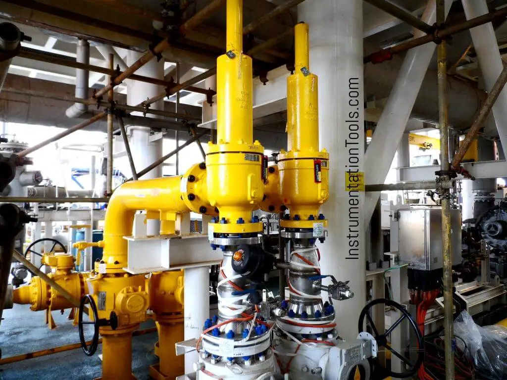
It is recommended that two valves in series be used to isolate fuel gas. This can take the form of double block safety valves (on/off) or a safety shutoff valve used in conjunction with a tight shutoff control valve.
A double block valve (on/off) arrangement, for one-out-of-two (1oo2) voting, allows for higher performance (SIL) ratings and requires less proof testing than a single block valve.
In many fired heater applications, the use of a bleed valve between two automated block valves has been discontinued due to environmental and safety implications of releasing fuel gas to the atmosphere. In the absence of a bleed valve, there may be increased concern for seat leakage of fuel gas into the heater. Since the automated block valves should maintain tight shutoff requirements, the purge cycle and sniffing a cold firebox with a portable combustibles analyzer prior to light off minimizes the process hazard. If the owner/operator elects to implement a valve proving system to verify seat integrity, it is recommended that the automated block valves be proven at the scheduled outage instead of waiting until the startup sequence. This facilitates valve testing and repair in a more practical and timely manner. The basis for seat leakage flow rates at the testing pressure, the corresponding pressure setpoints, and the delay timers that define pass/fail criteria should be documented during the project design phase.
A proof of closure valve diagnostic alarm is recommended if a safety shutoff valve fails to close within the prescribed time requirements (e.g. 5 seconds to 10 seconds or twice the valve stroke time).
The shutoff valve actuators should be sized with a safety factor of 25 % to 40 % more power in addition to typical considerations of the minimum instrument air pressure, operating conditions, and breakaway force or torque required to move the valve.
Note: API 598 leakage specification differs from that required in FM 7400 in that the allowable leakage is greater for the FM approved valves but the test duration is much longer.
While the FM 7400 approval standard requires rigorous testing of sample assemblies at various working pressures, a detailed actuator sizing analysis is not mandated. Consider the automated on-off actuator sizing detail as required in AWC Engineering Specifications and Quality procedures, an example excerpt of which is shown here.
First, there are six required torque values shown for the valve and actuator at the process conditions. For the spring return to close automated valve, these are as follows:
Note that the actuator torque data that corresponds to each of the six required torque values is compared so as to determine whether the required safety factor (Available Actuator Torque/Required Torque)is achieved. Then the generated actuator torque is compared to the Maximum Allowable Shaft Torque (MAST) value to ensure this value is not exceeded. Some customer engineering specifications mandate such an analysis for all automated on-off valves, and especially those in emergency shutdown or safety shutoff applications.
In addition, local engineering specifications may list the use of a certain type of solenoid, switch, actuator, etc. that has not previously been submitted to FM Global for approval. Given the expense and time required to obtain approval from Factory Mutual for such variances, choosing to purchase an assembly already approved can be compelling.
It is important to note that failure of an upstream pressure regulator can cause abnormally high fuel pressures at the Safety Shutoff Valves. While it is not typical for such pressures to exceed the ANSI limitations of the valve body, there have been cases where SSV’s have failed to actuate due to the higher than expected line pressure. For this reason, pressure relief (usually a pressure relieving regulator) is included in a branch line just downstream of the fuel gas regulator on the main fuel train. This relief regulator usually has tight shutoff and would only relieve in the case of a fuel train regulator failure. However, this option is sometimes not permitted by customers, especially if refinery fuel gas is used, due to the prohibition on allowing fuel gas to vent to atmosphere. In such cases, ensuring adequate actuator torque, even at an abnormal fuel gas pressure, is a preferable design choice. In general, pneumatically actuated valves are less likely to have pressure drop related actuation limitations when compared to electric motor/spring actuated safety shutoff valves.
The engineer selecting or specifying fuel gas safety shutoff valves will typically want to first determine what requirements the Authority Having Jurisdiction (AHJ)mandates for combustion safety. The AHJ may be a regulatory agency or position, such as a local fire marshal or state boiler inspector, but could be a company’s loss prevention inspector, insurance carrier or even a corporate engineering function. When the authority is FM Global, the installations must be “FM Global Accepted” and the use of products with FM approval may be one component of such acceptance.
The AHJ will ultimately determine whether automatic safety shutoff valves must be FM or CSA approved or specified/selected based upon another standard.
To reduce the potential of common mode failure for low fuel gas header pressure to both pilots and burners, it is recommended to separately source the pilots upstream of the fuel gas controller and safety shutoff valves to the main burners.
In addition to automatic safety shutoff valves, NFPA 86 is now requiring the installation of a manual equipment isolation valve for the fuel header which should be located in a safe area away from a potential fire hazard and is subject to regular periodic exercising and testing requirements.
Steam boilers, even those installed within process plants, may be subject to state inspection while other fired equipment, even with greater hazard potential, may not. In most cases in the United States, a combustion safety system is, at a minimum, designed to National Fire Protection Association standards but there are notable exceptions in actual practice. Even NFPA allows for flexibility in some areas regarding retroactivity of newer revisions of the aforementioned codes.
The aforementioned standards and recommended practices will provide design instruction on the number and placement of SSV’s in pilot and main gas lines. This is especially important to note for with installations with multiple burners each with individual fuel gas supply piping.
Regular (typically annual) through-leakage testing is typically required by the loss prevention entity or insurance carrier, or based upon plant safety standards. This is why fuel train piping is typically designed with leak test connections. Some FM Approved SSV’s, such as Maxon, are manufactured with leak test ports on the valve body itself. AWC can provide a leak testing procedure in accordance with manufacturer recommendations and standards such as ASME/ANSI 21.21. Such testing is usually accompanied by verification of the high and low gas pressure switches (or transmitters) and other routine procedures.
Pipe scale and corrosive condensates can lead to SSV failure. It is therefore not uncommon for some refineries to specify SSV’s with all stainless steel construction. In some cases, a routine cleaning of SSV’s can return the valves to within the allowable leakage threshold. Records should be maintained for these periodic tests.
In addition, automated leak testing using a start-up sequence and specifically placed pressure transmitters in the fuel train can be utilized to ensure testing occurs during every burner startup. Typical arrangements for automated testing can be provided by AWC.
Safety shut-off valves (SSOVs) are the primary automatic means of turning gas flow ON and OFF for furnaces, ovens, and in some cases, individual burners (keep in mind that a "manual shut-off valve" is always required). SSOVs are required by national codes and standards with at least two SSOVs required between a burner and the fuel supply. Besides that, they are a good way of keeping you and your factory from joining the upper atmosphere.

Curtiss-Wright"s selection of Pressure Relief Valves comes from its outstanding product brands Farris and Target Rock. We endeavor to support the whole life cycle of a facility and continuously provide custom products and technologies. Boasting a reputation for producing high quality, durable products, our collection of Pressure Relief Valves is guaranteed to provide effective and reliable pressure relief.
While some basic components and activations in relieving pressure may differ between the specific types of relief valves, each aims to be 100% effective in keeping your equipment running safely. Our current range includes numerous valve types, from flanged to spring-loaded, threaded to wireless, pilot operated, and much more.
A pressure relief valve is a type of safety valve designed to control the pressure in a vessel. It protects the system and keeps the people operating the device safely in an overpressure event or equipment failure.
A pressure relief valve is designed to withstand a maximum allowable working pressure (MAWP). Once an overpressure event occurs in the system, the pressure relief valve detects pressure beyond its design"s specified capability. The pressure relief valve would then discharge the pressurized fluid or gas to flow from an auxiliary passage out of the system.
Below is an example of one of our pilot operated pressure relief valves in action; the cutaway demonstrates when high pressure is released from the system.
Air pressure relief valves can be applied to a variety of environments and equipment. Pressure relief valves are a safety valve used to keep equipment and the operators safe too. They"re instrumental in applications where proper pressure levels are vital for correct and safe operation. Such as oil and gas, power generation like central heating systems, and multi-phase applications in refining and chemical processing.
At Curtiss-Wright, we provide a range of different pressure relief valves based on two primary operations – spring-loaded and pilot operated. Spring-loaded valves can either be conventional spring-loaded or balanced spring-loaded.
Spring-loaded valves are programmed to open and close via a spring mechanism. They open when the pressure reaches an unacceptable level to release the material inside the vessel. It closes automatically when the pressure is released, and it returns to an average operating level. Spring-loaded safety valves rely on the closing force applied by a spring onto the main seating area. They can also be controlled in numerous ways, such as a remote, control panel, and computer program.
Pilot-operated relief valves operate by combining the primary relieving device (main valve) with self-actuated auxiliary pressure relief valves, also known as the pilot control. This pilot control dictates the opening and closing of the main valve and responds to system pressure. System pressure is fed from the inlet into and through the pilot control and ultimately into the main valve"s dome. In normal operating conditions, system pressure will prevent the main valve from opening.
The valves allow media to flow from an auxiliary passage and out of the system once absolute pressure is reached, whether it is a maximum or minimum level.
When the pressure is below the maximum amount, the pressure differential is slightly positive on the piston"s dome size, which keeps the main valve in the closed position. When system pressure rises and reaches the set point, the pilot will cut off flow to the dome, causing depressurization in the piston"s dome side. The pressure differential has reversed, and the piston will rise, opening the main valve, relieving pressure.
When the process pressure decreases to a specific pressure, the pilot closes, the dome is repressurized, and the main valve closes. The main difference between spring-loaded PRVs and pilot-operated is that a pilot-operated safety valve uses pressure to keep the valve closed.
Pilot-operated relief valves are controlled by hand and are typically opened often through a wheel or similar component. The user opens the valve when the gauge signifies that the system pressure is at an unsafe level; once the valve has opened and the pressure has been released, the operator can shut it by hand again.
Increasing pressure helps to maintain the pilot"s seal. Once the setpoint has been reached, the valve opens. This reduces leakage and fugitive emissions.
At set pressure the valve snaps to full lift. This can be quite violent on large pipes with significant pressure. The pressure has to drop below the set pressure in order for the piston to reseat.
The pilot is designed to open gradually, so that less of the system fluid is lost during each relief event. The piston lifts in proportion to the overpressure.
At Curtiss-Wright we also provide solutions for pressure relief valve monitoring. Historically, pressure relief valves have been difficult or impossible to monitor. Our SmartPRV features a 2600 Series pressure relief valve accessorized with a wireless position monitor that alerts plant operators during an overpressure event, including the time and duration.
There are many causes of overpressure, but the most common ones are typically blocked discharge in the system, gas blowby, and fire. Even proper inspection and maintenance will not eliminate the occurrence of leakages. An air pressure relief valve is the only way to ensure a safe environment for the device, its surroundings, and operators.
A PRV and PSV are interchangeable, but there is a difference between the two valves. A pressure release valve gradually opens when experiencing pressure, whereas a pressure safety valve opens suddenly when the pressure hits a certain level of over pressurization. Safety valves can be used manually and are typically used for a permanent shutdown. Air pressure relief valves are used for operational requirements, and they gently release the pressure before it hits the maximum high-pressure point and circulates it back into the system.
Pressure relief valves should be subject to an annual test, one per year. The operator is responsible for carrying out the test, which should be done using an air compressor. It’s imperative to ensure pressure relief valves maintain their effectiveness over time and are checked for signs of corrosion and loss of functionality. Air pressure relief valves should also be checked before their installation, after each fire event, and regularly as decided by the operators.
Direct-acting solenoid valves have a direct connection with the opening and closing armature, whereas pilot-operated valves use of the process fluid to assist in piloting the operation of the valve.
A control valve works by varying the rate of fluid passing through the valve itself. As the valve stem moves, it alters the size of the passage and increases, decreases or holds steady the flow. The opening and closing of the valve is altered whenever the controlled process parameter does not reach the set point.
Control valves are usually at floor level or easily accessible via platforms. They are also located on the same equipment or pipeline as the measurement and downstream or flow measurements.
An industrial relief valve is designed to control or limit surges of pressure in a system, most often in fluid or compressed air system valves. It does so as a form of protection for the system and defending against instrument or equipment failure. They are usually present in clean water industries.
A PRV is often referred to as a pressure relief valve, which is also known as a PSV or pressure safety valve. They are used interchangeably throughout the industry depending on company standards.
Seismic shut-off valves are a simple, but effective way to ensure you never experience a gas fire after an earthquake. They are designed for earthquakes, accidents and any event of impact. We have installed thousands of automatic gas shut off valves to the manufacture’s specification to ensure safe, trouble free use.
The seismic valves work on a simple, consistent and accurate principle. A sensor moves when the valve is subjected to a 5.4 magnitude or larger earthquake, releasing the valve float which blocks the line and prevents gas going in to the building. The valve is then manually reset once a safety inspection has been done and you’re sure there are no leaks in the building.
Each valve is tested and certified before leaving the factory to meet approval from the State Board of Architect and LA Counties stringent requirements. They are tested to ASCE 25-97, State of California 12-23-1 & ANSI Z21.70-1981 Standards for Seismic Gas Valves.
Some cities and counties in California have regulations that require the installation of automatic gas shut-off devices, which may include excess flow gas shut-off valves and/or seismic gas shut-off valves. Regulations vary, but generally apply to new building construction, or significant alterations or additions to existing buildings.
If a customer installs an automatic gas shut-off valve, it should be one that is certified by the State of California and it should be installed by a licensed plumbing contractor in accordance to the manufacturers instructions.PG&Edoes not install or service seismic actuated or excess flow gas shut-off valves, or recommend specific contractors for customer applications.
Non-emergency shut-offs will occur if the automatic gas shut-off is not installed according to manufacturer’s specifications. For example, the impact of heavy vehicles can trigger a non-emergency shut-off. They operate on movement and shut off the supply of gas to a building, when triggered by a 5.4 magnitude or larger Earthquake.

An excess flow valve is a mechanical safety device that may be installed on a natural gas service line, and is designed to automatically shut off the flow of natural gas in the service line in the event of a significant break, puncture or severance in the line.
An excess flow valve operates similar to electrical circuit breakers that trip when the electricity current exceeds its limit. The excess flow valve is tripped by an excess flow of gas, causing a spring loaded device inside the valve to automatically restrict the flow of gas. The valve automatically resets or reopens when the excess flow of gas has ceased or service line gas pressure is significantly reduced.
No. An excess flow valve does not protect against small leaks on the service line or gas meter or leaks beyond the meter assembly, such as those involving a customer’s house piping or customer appliance malfunction. It is designed to activate when the service line is significantly damaged due to excavation or other similar activities. Prevention of service line damage remains the best form of protection and all customers can place a free 811 call to have buried utilities marked before digging.
An excess flow valve is designed to allow normal operation of the service line. It will automatically restrict the flow of natural gas only when the service line has been significantly damaged and the flow of natural gas exceeds prescribed limits. An excess flow valve is not designed nor capable of restricting the flow of natural gas inside your home or structure in the event of damage to your house piping located downstream of the gas meter.
Leave the area immediately and call 911 and Smyrna Natural Gas at 615-355-5740 option 4 (call from a neighbor’s house or from another location far from the smell of natural gas)
Federal regulations require that existing customers receive notice of their option to request the installation of an excess flow valve on qualifying service lines.
The cost of installing an excess flow valve on an existing natural gas service line will be the sole responsibility of the customer requesting the installation.
The cost to install an excess flow valve varies depending on the location and difficulty of the installation; however, on average, the cost to install an excess flow valve on an eligible existing service line is estimated to be in excess of $950.
The excess flow valve is installed on the natural gas service line that runs underground between the gas main (usually located in or near the street, alley or utility right-of-way) and the gas meter on the customer’s property. Installation of an excess flow valve requires excavation near the natural gas main to expose the service line prior to installation. All areas excavated will be restored once installation is complete.
Smyrna will send out a representative to your property to determine if an excess flow valve can be installed. Due to operating characteristics and limitations in some instances, an excess flow valve cannot be installed. Each customer location will be evaluated upon request.
The device is designed to last the lifetime of the natural gas line. However, if your natural gas service line is replaced in connection with overall system maintenance activities, the excess flow valve will also be replaced.
Installation of an excess flow valve requires digging so that the service line is exposed prior to installation. Smyrna Natural Gas or its contractor will restore property to its original condition, to the extent reasonably practicable, as part of the overall project cost.
Yes. Installation of the excess flow valve will require us to temporarily shut off the gas supply to your property. As part of the installation process, your existing houseline piping must be retested and appliance pilots will be re-lit if your houseline piping and appliances are operating normally. If the houseline test fails or appliances do not pass inspection, you will be responsible for repairs before natural gas service can be fully restored.
Installation of the excess flow valve will be scheduled at a mutually agreeable date, subject to approval from permitting authorities, payment arrangements, work crew scheduling and weather conditions. The length of time to install will vary based on the complexity of the installation.
If someone has hired a contractor to do work that requires excavation, they should call 811 themselves or ask the contractor to do so before work begins. Property owners who see someone preparing to dig on their property and don’t see paint lines or flags marking the location of underground utilities, should tell the workers to STOP and call 811 before they dig.

WITT is a manufacturer of Pressure relief valvesor Safety relief valves for technical gases. They are designed to protect against overpressure by discharging pressurized gases and vapors from pipelines, pressure vessels and plant components. Safety relief valves (SRV) are often the last line of defense against explosion – and such an explosion could be fatal. Other common names for safety relief valves are pressure relief valve (PRV), safety valve, pressure safety valve, overpressure valve, relief valve or blow-off valve.
WITT safety valves are very precise. They are individually preset to open at a predetermined pressure within the range 0.07 to 652 Psi. Their small size and orientation-independent installation allow a wide range of connection options. WITT relief valves also stand out due to their high blow-off flow rates of up to 970m³/h. They can be used within a temperature range of -76° F to +518°F and even with very low pressures.
For maximum safety, WITT undertakes 100 % testing of each safety relief valve before it is delivered. In addition, WITT offers individual testing of eachsafety valveby the TÜV, with their certificate as proof of the correct set pressure.
WITTsafety relief valvesare direct-acting, spring-loaded valves. When the preset opening pressure is reached, a spring-loaded element in the valve gives way and opens, and the pressure is relieved. Once the pressures are equalized, the valve closes automatically and can be reactivated any time the pressure rises again. Depending on the application and the nature of the gas, the safety relief valvescan either discharge to atmosphere, or via a connected blow-off line. The opening pressure of the safety valves is preset by WITT at the factory according to the customer’s requirements.
Safety relief valvesare used in numerous industries and industrial applications where, for example, gases pass through pipelines or where special process vessels have to be filled with gas at a certain pressure.
These include, among other things:Pipeline, plant and container constructionIndustrial furnace constructionInsulators and reactors (e.g. “glovebox” systems)hydrogen-powered vehiclesAdditive manufacturing (3D printer)
For most industrial applications using technical gases, brass is usually the standard material of construction of thesafety relief valvebody/housing. For the use of pressure relief valves with aggressive and corrosive gases, the housings are made of high-quality stainless steel (1.4541/AISI 321, 1.4404/AISI 316L, 1.4305/AISI 303 or 1.4571/AISI 316Ti). The use of aluminium as a housing material is also possible.
Depending on the type of gas used and individual customer requirements, various sealing materials and elastomers are available to ensure the safety of your systems under even the most difficult conditions.
WITT pressure relief valves are available with different connections. In addition to the standard versions with the usual internal or external threads, special versions with KF or CF flanges, VCR or UNF threads can also be ordered. Special adapters for connecting the safety relief valve to a blow-off line are also available.

Standard materials include 316 stainless steel bodies and removable seat glands with 17-4PH stem and seal ring. Standard O-ring material on the stem is Viton. The seat material is Peek. Valves may be used up to 400°F with standard Vtion O-ring or 450°F with the Kalrez O-ring option.
Inlet connections are for 9/16" O.D. tubing (HF9) with adapters for other sizes available. Outlet connections are 1/2" NPT. These valves are not recommended for use below 1,500 psi, and are not readily adjustable in the field without proper test equipment. Pressure settings are made at the factory and valves are tagged accordingly.
HiP relief valves are now available with CE marking. These products will proudly be marked with the CE symbol, signifying they comply with the stringent requirements of the Pressure Equipment Directive (PED). To order, add -CE to your relief valve part number.


 8613371530291