
how does a gas safety valve work quotation

Most modern appliances have safety features built in, but your gas oven safety valve is arguably the most important. If an electrical appliance malfunctions, it can cause a fire, but a misfiring gas oven could potentially blow up your house. You don"t really need to know how the safety mechanism works to use your oven, but you may find that it gives you some extra peace of mind.
Broadly speaking, there are two ways a built-in safety mechanism can work. One option is that it remains "open" by default and to shut off if certain conditions are met. That"s how fuses and circuit breakers work in an electrical circuit: Ordinarily, the electricity is free to flow, but if the current grows too large, the fuse or breaker will blow and cut off the circulation of electricity.
The other option is for your safety mechanism to be "closed" by default and allow a device to operate only when the correct conditions are met. That"s how a gas oven safety valve works. Gas ordinarily is prevented from flowing, and if the valve is working correctly, it opens only when you want to light your oven.
Many gas stoves use what"s called a "hot surface igniter," a bar or element (similar to the ones on your stovetop) that gets hot enough to ignite the gas on contact. Gas oven safety valves on stoves with this type of ignition system take a couple of different approaches.
In one approach, a bimetallic strip operates the valve. It harnesses a simple scientific principle: Metals expand and contract at different rates when they"re heated and cooled. If you bond two suitable metals together in one strip, that strip will flex to a predictable degree as the temperature goes up and down. Wall-mount thermostats often use this principle, as do analog oven thermometers and the thermometer in the lid of your gas grill.
As appliance-repair website PartSelect explains, turning on your gas oven causes electricity to flow into the heating element of your hot surface igniter. As the igniter heats up, it warms a bimetallic strip inside your gas oven safety valve. When the igniter reaches its operating temperature, the bimetallic strip opens the valve and allows the gas to flow, igniting as it crosses the heated surface.
One intriguing thing about electricity is that a change in temperature can affect how well it passes through certain materials. For example, a lot of research revolves around superconductors – materials that offer very little resistance to an electrical current – but superconductors typically must be heavily chilled to work.
According to heating-equipment vendor Anglo Nordic, gas oven safety valves use a variation of that principle to operate. In these stoves, the flow of electrical current through the hot surface igniter becomes the control mechanism. The igniter"s bar is made of a material that offers less and less resistance to electricity as it heats. When it reaches the temperature required to ignite the gas, its resistance becomes low enough to trip the safety valve and open the flow of gas.
More modern ranges use an electrical igniter. When you turn on your oven, the gas begins flowing immediately, and it sends an electrical current to a piezo electric igniter. The current makes the igniter spark (like the manual igniter on your gas grill) and lights the oven"s burner. In this case, the safety valve works in the opposite way: An electronic sensor checks for the heat caused by ignition after a few seconds, and if it"s absent, it will close the valve and shut off the flow of gas.
It"s worth pointing out that not all gas ovens have a safety valve in the conventional sense. Older stoves simply use a pilot light, a small but constant flow of gas, which, in turn, feeds a small, candle-like flame. You essentially are the safety mechanism in this system: It"s up to you to check that the pilot is lit. When you turn on the gas manually, the small pilot flame ignites the main flame. It"s a mechanically simple system, which makes it durable, and for that reason, you"ll still see it used on commercial restaurant ranges, which must stand up to decades of heavy use.

Boiler explosions have been responsible for widespread damage to companies throughout the years, and that’s why today’s boilers are equipped with safety valves and/or relief valves. Boiler safety valves are designed to prevent excess pressure, which is usually responsible for those devastating explosions. That said, to ensure that boiler safety valves are working properly and providing adequate protection, they must meet regulatory specifications and require ongoing maintenance and periodic testing. Without these precautions, malfunctioning safety valves may fail, resulting in potentially disastrous consequences.
Boiler safety valves are activated by upstream pressure. If the pressure exceeds a defined threshold, the valve activates and automatically releases pressure. Typically used for gas or vapor service, boiler safety valves pop fully open once a pressure threshold is reached and remain open until the boiler pressure reaches a pre-defined, safe lower pressure.
Boiler relief valves serve the same purpose – automatically lowering boiler pressure – but they function a bit differently than safety valves. A relief valve doesn’t open fully when pressure exceeds a defined threshold; instead, it opens gradually when the pressure threshold is exceeded and closes gradually until the lower, safe threshold is reached. Boiler relief valves are typically used for liquid service.
There are also devices known as “safety relief valves” which have the characteristics of both types discussed above. Safety relief valves can be used for either liquid or gas or vapor service.
Nameplates must be fastened securely and permanently to the safety valve and remain readable throughout the lifespan of the valve, so durability is key.
The National Board of Boiler and Pressure Vessel Inspectors offers guidance and recommendations on boiler and pressure vessel safety rules and regulations. However, most individual states set forth their own rules and regulations, and while they may be similar across states, it’s important to ensure that your boiler safety valves meet all state and local regulatory requirements.
The National Board published NB-131, Recommended Boiler and Pressure Vessel Safety Legislation, and NB-132, Recommended Administrative Boiler and Pressure Vessel Safety Rules and Regulationsin order to provide guidance and encourage the development of crucial safety laws in jurisdictions that currently have no laws in place for the “proper construction, installation, inspection, operation, maintenance, alterations, and repairs” necessary to protect workers and the public from dangerous boiler and pressure vessel explosions that may occur without these safeguards in place.
The documents are meant to be used as a guide for developing local laws and regulations and also may be used to update a jurisdiction’s existing requirements. As such, they’re intended to be modifiable to meet any jurisdiction’s local conditions.
The American Society of Mechanical Engineers (ASME) governs the code that establishes guidelines and requirements for safety valves. Note that it’s up to plant personnel to familiarize themselves with the requirements and understand which parts of the code apply to specific parts of the plant’s steam systems.
High steam capacity requirements, physical or economic constraints may make the use of a single safety valve impossible. In these cases, using multiple safety valves on the same system is considered an acceptable practice, provided that proper sizing and installation requirements are met – including an appropriately sized vent pipe that accounts for the total steam venting capacity of all valves when open at the same time.
The lowest rating (MAWP or maximum allowable working pressure) should always be used among all safety devices within a system, including boilers, pressure vessels, and equipment piping systems, to determine the safety valve set pressure.
General guidance on proper installation may seem like common sense to experienced installers and inspectors. A few of the most important guidelines and best practices include:
Avoid isolating safety valves from the system, such as by installing intervening shut-off valves located between the steam component or system and the inlet.
Contact the valve supplier immediately for any safety valve with a broken wire seal, as this indicates that the valve is unsafe for use. Safety valves are sealed and certified in order to prevent tampering that can prevent proper function.
Avoid attaching vent discharge piping directly to a safety valve, which may place unnecessary weight and additional stress on the valve, altering the set pressure.

Gas chain: These types of gas valves are quite common and require the operator to manually turn a valve to open or close the flow of gas to the furnace.
This little rod basically lets the gas valve know whether or not combustion (fire) is actually happening or not and whether the gas valve should remain open or closed.
If the thermocouple does not maintain a certain temperature, it knows that no combustion (fire) is happening and the gas valve closes to prevent gas from just leaking into your home for no reason.
When you need it: New construction, process conditions have changed, your valve is not performing as you expect, you want to consider modifications, or you just aren’t sure what you need. Our engineering team is available to assist with sizing and selection to get you the valve you need.
Automatic control valves must be sized to adequately control the process application for which it is intended. With nominal process data, calculations are performed to determine the flow capacity needed for the application, and that required capacity is matched to a type and size of valve and its “Cv”, or flow coefficient. If not properly sized, a control valve may not pass the required flow or may not operate in a range needed to effectively control the process.
Much like the control valve, the actuator must be sized to match the amount of force required to operate the valve. Without proper sizing, an actuator can be sluggish and not respond adequately to control signal changes, resulting in instability of the process being controlled. A missized actuator can also keep the valve from attaining its designed shutoff classification, and objectionable leakage may occur.
Our Engineering Spec Sheet conforms to ISA Form 20 – other engineered data sheets, such as those from the OEM or a previous supplier, are also accepted.
Easy-to-follow instructions are included in the document. Fill out as much of the Process Data section of the datasheet as you can, along with any other information or expectations.
Valve type and size for the application are selected by an application engineer once the required flow capacities are calculated. Also essential is specifying the appropriate materials of construction of the process wetted parts: trim, valve body/bonnet, packing.

Working in the HVAC, combustion, propane, and industrial markets requires tools and equipment that can handle the demands of process complexity in a safe and efficient manner. One area you should never skimp on is that of your gas regulators.
These handy devices work hard to ensure the gas flowing through the lines into the equipment does so at the right pressure. Too much gas pressure can lead to a catastrophic explosion, harming others and destroying property. Conversely, not having enough pressure will render your equipment useless.
We understand that the world of regulators can be a little confusing. Each type serves a different purpose based on the application. Although you can rely on experts like us to help you out, understanding what a regulator is, how it works, the difference between pressure reduction and pressure regulation, and dual-stage vs. single-stage, will aid you in finding the best product for the job.
Designed in 1835, the regulator’s concept is easy, and its impact has been long-lasting. There are various types of regulators, but their function is the same: to use a valve system to control natural gas or propane pressure or other gas flow.
Common appliances that use regulators include gas stoves, propane grills, or oxy-fuel bottles for welding. Each type of regulator’s components consists of a set spring attached to a rod that runs down from a set screw through a diaphragm into the valve.
There are three primary operating components working together to regulate the pressure within the valve. The loading mechanism determines the delivery pressure. Most often, it is a spring. The sensing element, or diaphragm, senses the force against the spring. Finally, the control element accomplishes the reduction of the inlet pressure through to the outlet pressure.
Gas enters the regulator’s chamber, putting pressure on the diaphragm. The diaphragm then moves upward as controlled by the set spring. This allows a specific flow of fuel from the source to the appliance or device. Adjusting the control knob determines the rate of flow and the pressure. Turning clockwise will push the diaphragm down and allow more gas to come into the valve. Turn counter-clockwise to reduce the amount of fuel and pressure.
The mechanics of the gas regulator work well together. However, there is another component that comes into play called the surrounding air. Atmospheric pressure, based on the elevation above sea level that the building sits, will affect gas pressure. The inner parts work by sensing the pressure both upstream and downstream. The air pressure affects the way the regulator senses downstream pressure.
The application between the two types is the main difference. A pressure reduction regulator is used to reduce the input pressure of the gas, so that it is at the ideal pressure on the outset. It is a normally open valve installed upstream of the pressure-sensitive equipment it needs to regulate, as it controls downstream pressure.
Pressure regulation is often called a back-pressure regulator or back-pressure valve. Its purpose is to maintain a set pressure at the inlet. It is a normally closed valve and is installed in parallel with or just after sensitive equipment to maintain upstream pressure.
Dual-stage regulators utilize two regulators within the same housing, which operate to reduce pressure in two steps instead of only one step. At the first stage, the pressure of the supply (inlet) gas is reduced at an intermediate stage, generally about three times the maximum working pressure. The second stage further reduces the pressure to a reasonable working pressure. Sometimes, a dual-stage regulator may have two safety valves to lessen the possibility of an explosion.
Single-stage regulators only have one regulator in which the gas supply enters, and the pressure is reduced. The delivery pressure is not as controllable as a dual-stage one is; thus, it should be used in operations where it can be monitored and easily adjusted as required, or the source pressure is nearly constant. An example of a single-stage regulator is a line regulator.
Choosing which type to use should be based on the required consistency of gas flow needed for operating. Consider what kind of gas flow is required, and then make your choice.
The types of regulators are extensive and include appliance, line and service, pilot operated, direct acting, high pressure, back pressure, relief valves, and propane regulators. You can even find specialty items such as high-purity regulators for those unique jobs. At Norgas Controls, you can find the right type of regulator for your specific needs.
Norgas’ team of experts can help you find the right gas regulator for your application from our extensive inventory or design a custom solution to meet your specific needs. We have an extensive inventory of gas regulators ready to ship within 24-hours of your order.
Need to set up a quote for a client? Contact us. We will give you everything you need, from pricing to literature, to provide your customer with an accurate quote that will give you a leg up against the competition. We are your one-stop-shop for all your gas regulators, meters, valves, and accessories.

While it"s possible to manually shut off your natural gas, the following specialized valves are available that can automatically shut off your service in case of an emergency:
Earthquake natural gas shut-off valve (also known as a seismic natural gas shut-off valve) automatically shuts off your natural gas service when an earthquake of a sufficient magnitude occurs at your home.
An excess-flow valve (EFV) automatically closes and restricts the flow of natural gas in the event an underground pipe is damaged or if there is a significant increase in the flow of natural gas to the meter.
If you want to have an earthquake natural gas shut-off installed, or are required to have one by your insurance company or the local Department of Building and Safety, the valve must be installed on your house line.
If installation requires natural gas service closure, you"ll need to contact us to shut off the service and restore service when installation is completed. Natural gas service shut off and restoration of service orders can be scheduled by contacting us at 1-800-427-2200.
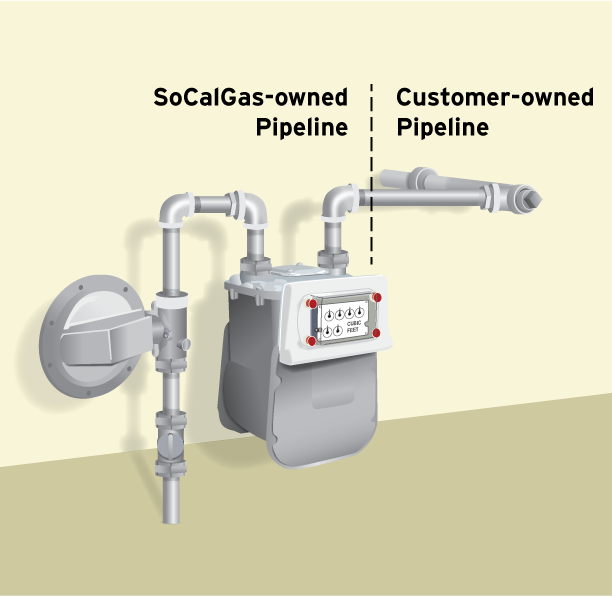
Under the regulations of the California Public Utilities Commission (CPUC), General Order 112-E, only SoCalGas® or its certified contractors are authorized to operate the natural gas service shut-off valve.
When you hire a qualified professional to install your earthquake valve, you"ll need to make sure that the valve is installed on your house line, not on SoCalGas" facilities. SoCalGas" facilities include all of the pipe fittings installed and maintained by SoCalGas, up to and including the last elbow or tee connecting to your house line. See the diagram below for to see where your house line starts.
All unauthorized valve installations found on SoCalGas" facilities will be removed. In addition, earthquake valves are not permitted in utility curb meter vaults.
If an earthquake or other significant event causes your earthquake shut-off or excess-flow valve to close, you can follow the manufacturer"s instructions for resetting the valve so that natural gas flows again. However, we recommend that you contact a qualified professional or SoCalGas to reset the valve, and to perform a safety check of your natural gas appliances before they are placed back in operation to verify that no natural gas leaks exist, and to re-light your pilot lights.
Remember that following a major emergency it may take many days or even weeks before someone can come to your location. (SoCalGas charges a fee to reset valves and re-light pilot lights when your earthquake shut-off valve has closed due to a non-earthquake occurrence.)
Price: The cost of the valve is going to vary based on the type and size of the valve, as well as the installation requirements and the company installing it.
Choosing a valve: In order to choose the right valve size and manufacturer, contact your local Department of Building and Safety to find out their earthquake valve requirements.
Where to buy a valve: You can purchase an earthquake valve at supply retailers, licensed plumbing contractors, or directly from the valve manufacturer.
Using a contractor: You can hire a qualified professional to install the earthquake or excess-flow valve on your house line. SoCalGas will not install a valve for you.
Effective February 10, 2002, California Public Utility Commission (CPUC) Decision 01-11-068 prohibits installation of an earthquake valve on SoCalGas" facilities. In addition, SoCalGas no longer installs earthquake shut-off valves for its customers, and does not allow any customer owned equipment, including excess-flow valves, be installed on SoCalGas" facilities.
If you have an earthquake valve that was installed by SoCalGas or one of its authorized contractors on or before the February 10, 2002 cutoff date, that is located on SoCalGas" facilities, with proper documentation your installation may be allowed to remain in place. Authorized contractors are those who participated in SoCalGas" earthquake program and were trained by SoCalGas to work on their facilities.
Additional information regarding earthquake valves and natural gas service restoration after a valve activates can be found in Tariff Book, Rule 10, Section G, "Earthquake Valve Service."
An Excess Flow Valve, or EFV, is a safety device installed on natural gas distribution pipelines to automatically close and restrict the flow of natural gas in the event an underground pipe is damaged or if there is a significant increase in the flow of natural gas to the meter. These conditions are typically caused by digging or construction but can also be caused by damage to your natural gas meter by a vehicle impact.
EFV can reduce the risk of explosions, fires, and personal injury because they close or restrict any unplanned or excessive natural gas flow. Installation of an EFV will not protect a customer from household appliance malfunctions, small punctures in underground pipelines, and pipeline damage from earthquakes or flooding. It is
important to understand that an EFV does not shut off the flow of natural gas completely. Some leakage may still occur resulting in a hazardous condition.
An EFV is installed on the service pipeline that runs underground between the natural gas main (usually located in or near the street, alley or easement) and the SoCalGas® meter on the customer’s property).
The best way to prevent damage to a natural gas pipeline due to digging is to call 811, the Underground Service Alert program, at least two working days before digging. Underground Service Alert will coordinate with SoCalGas to mark the locations of buried utility-owned lines - absolutely FREE.
If you are interested in having an EFV installed on the service pipeline serving you[1], please call SoCalGas at 1-800-427-2200. SoCalGas will first check to see if your service already has an EFV installed and, if not, an estimate to install the EFV will be provided. The cost to install an EFV can vary widely depending on site specific conditions and can range from $2,500 to $5,000 or more.
If you decide to have an EFV installed, we will coordinate with you to schedule the installation (note that it is possible that natural gas service will be interrupted to install the EFV). The construction crew will dig around the natural gas line in order to install the EFV and when the job is complete natural gas service will be restored (if it was shut off). If paving or concrete needs repair that work will be scheduled at a later date.

En Español | Need help now? Please see below for emergency assistance, outage reporting and other customer service. We apologize for the inconvenience and are working hard to restore our website as quickly as possible.
This website is using a security service to protect itself from online attacks. The action you just performed triggered the security solution. There are several actions that could trigger this block including submitting a certain word or phrase, a SQL command or malformed data.
An Earthquake Shut-off Valve is a Gas Safety Device that is installed on your gas meter and automatically shuts-off the gas supply entering the structure in a 5.2 or greater earthquake.
Earthquake valves are important because they help mitigate damage caused by earthquakes. Earthquakes may break gas lines and cause gas leaks. An earthquake valve will stop the gas supply entering the structure. This will help prevent explosive fire caused by gas leaks. Earthquake valves protect your home, property and loved ones from harm in the event of an earthquake of magnitude 5.2 or higher.
Depending on the municipality, earthquake valves are required in different situations. Cities, with a high risk of earthquakes, are adopting new codes requiring earthquake valves to be installed in order to help protect their communities. Los Angeles, Santa Monica and Culver City are just a few of the cities which require earthquake valves. These cities require professional earthquake valves to be installed whenever you are building a new home, selling a home, or renovating your property in excess of $10,000.
Safe Gas Services provides complete installation and retrofitting services for residential, commercial and industrial structures throughout the greater Los Angeles area to ensure that your property meets city and state regulations and to keep you safe.

Safety shut-off valves (SSOVs) are the primary automatic means of turning gas flow ON and OFF for furnaces, ovens, and in some cases, individual burners (keep in mind that a "manual shut-off valve" is always required). SSOVs are required by national codes and standards with at least two SSOVs required between a burner and the fuel supply. Besides that, they are a good way of keeping you and your factory from joining the upper atmosphere.

Most people are unaware that there is a Gas Safety Shut Off Valve available and even modern homes do not currently have one installed. In case of an earthquake, natural disaster or accident, this valve will automatically shut off the gas to your home and protect you and the ones you care about!

A safety valve is a valve that acts as a fail-safe. An example of safety valve is a pressure relief valve (PRV), which automatically releases a substance from a boiler, pressure vessel, or other system, when the pressure or temperature exceeds preset limits. Pilot-operated relief valves are a specialized type of pressure safety valve. A leak tight, lower cost, single emergency use option would be a rupture disk.
Safety valves were first developed for use on steam boilers during the Industrial Revolution. Early boilers operating without them were prone to explosion unless carefully operated.
Vacuum safety valves (or combined pressure/vacuum safety valves) are used to prevent a tank from collapsing while it is being emptied, or when cold rinse water is used after hot CIP (clean-in-place) or SIP (sterilization-in-place) procedures. When sizing a vacuum safety valve, the calculation method is not defined in any norm, particularly in the hot CIP / cold water scenario, but some manufacturers
The earliest and simplest safety valve was used on a 1679 steam digester and utilized a weight to retain the steam pressure (this design is still commonly used on pressure cookers); however, these were easily tampered with or accidentally released. On the Stockton and Darlington Railway, the safety valve tended to go off when the engine hit a bump in the track. A valve less sensitive to sudden accelerations used a spring to contain the steam pressure, but these (based on a Salter spring balance) could still be screwed down to increase the pressure beyond design limits. This dangerous practice was sometimes used to marginally increase the performance of a steam engine. In 1856, John Ramsbottom invented a tamper-proof spring safety valve that became universal on railways. The Ramsbottom valve consisted of two plug-type valves connected to each other by a spring-laden pivoting arm, with one valve element on either side of the pivot. Any adjustment made to one of valves in an attempt to increase its operating pressure would cause the other valve to be lifted off its seat, regardless of how the adjustment was attempted. The pivot point on the arm was not symmetrically between the valves, so any tightening of the spring would cause one of the valves to lift. Only by removing and disassembling the entire valve assembly could its operating pressure be adjusted, making impromptu "tying down" of the valve by locomotive crews in search of more power impossible. The pivoting arm was commonly extended into a handle shape and fed back into the locomotive cab, allowing crews to "rock" both valves off their seats to confirm they were set and operating correctly.
Safety valves also evolved to protect equipment such as pressure vessels (fired or not) and heat exchangers. The term safety valve should be limited to compressible fluid applications (gas, vapour, or steam).
For liquid-packed vessels, thermal relief valves are generally characterized by the relatively small size of the valve necessary to provide protection from excess pressure caused by thermal expansion. In this case a small valve is adequate because most liquids are nearly incompressible, and so a relatively small amount of fluid discharged through the relief valve will produce a substantial reduction in pressure.
Flow protection is characterized by safety valves that are considerably larger than those mounted for thermal protection. They are generally sized for use in situations where significant quantities of gas or high volumes of liquid must be quickly discharged in order to protect the integrity of the vessel or pipeline. This protection can alternatively be achieved by installing a high integrity pressure protection system (HIPPS).
In the petroleum refining, petrochemical, chemical manufacturing, natural gas processing, power generation, food, drinks, cosmetics and pharmaceuticals industries, the term safety valve is associated with the terms pressure relief valve (PRV), pressure safety valve (PSV) and relief valve.
The generic term is Pressure relief valve (PRV) or pressure safety valve (PSV). PRVs and PSVs are not the same thing, despite what many people think; the difference is that PSVs have a manual lever to open the valve in case of emergency.
Relief valve (RV): an automatic system that is actuated by the static pressure in a liquid-filled vessel. It specifically opens proportionally with increasing pressure
Pilot-operated safety relief valve (POSRV): an automatic system that relieves on remote command from a pilot, to which the static pressure (from equipment to protect) is connected
Low pressure safety valve (LPSV): an automatic system that relieves static pressure on a gas. Used when the difference between the vessel pressure and the ambient atmospheric pressure is small.
Vacuum pressure safety valve (VPSV): an automatic system that relieves static pressure on a gas. Used when the pressure difference between the vessel pressure and the ambient pressure is small, negative and near to atmospheric pressure.
Low and vacuum pressure safety valve (LVPSV): an automatic system that relieves static pressure on a gas. Used when the pressure difference is small, negative or positive and near to atmospheric pressure.
In most countries, industries are legally required to protect pressure vessels and other equipment by using relief valves. Also, in most countries, equipment design codes such as those provided by the ASME, API and other organizations like ISO (ISO 4126) must be complied with. These codes include design standards for relief valves and schedules for periodic inspection and testing after valves have been removed by the company engineer.
Today, the food, drinks, cosmetics, pharmaceuticals and fine chemicals industries call for hygienic safety valves, fully drainable and Cleanable-In-Place. Most are made of stainless steel; the hygienic norms are mainly 3A in the USA and EHEDG in Europe.
The first safety valve was invented by Denis Papin for his steam digester, an early pressure cooker rather than an engine.steelyard" lever a smaller weight was required, also the pressure could easily be regulated by sliding the same weight back and forth along the lever arm. Papin retained the same design for his 1707 steam pump.Greenwich in 1803, one of Trevithick"s high-pressure stationary engines exploded when the boy trained to operate the engine left it to catch eels in the river, without first releasing the safety valve from its working load.
Although the lever safety valve was convenient, it was too sensitive to the motion of a steam locomotive. Early steam locomotives therefore used a simpler arrangement of weights stacked directly upon the valve. This required a smaller valve area, so as to keep the weight manageable, which sometimes proved inadequate to vent the pressure of an unattended boiler, leading to explosions. An even greater hazard was the ease with which such a valve could be tied down, so as to increase the pressure and thus power of the engine, at further risk of explosion.
Although deadweight safety valves had a short lifetime on steam locomotives, they remained in use on stationary boilers for as long as steam power remained.
Weighted valves were sensitive to bouncing from the rough riding of early locomotives. One solution was to use a lightweight spring rather than a weight. This was the invention of Timothy Hackworth on his leaf springs.
These direct-acting spring valves could be adjusted by tightening the nuts retaining the spring. To avoid tampering, they were often shrouded in tall brass casings which also vented the steam away from the locomotive crew.
The Salter coil spring spring balance for weighing, was first made in Britain by around 1770.spring steels to make a powerful but compact spring in one piece. Once again by using the lever mechanism, such a spring balance could be applied to the considerable force of a boiler safety valve.
The spring balance valve also acted as a pressure gauge. This was useful as previous pressure gauges were unwieldy mercury manometers and the Bourdon gauge had yet to be invented.
Paired valves were often adjusted to slightly different pressures too, a small valve as a control measure and the lockable valve made larger and permanently set to a higher pressure, as a safeguard.Sinclair for the Eastern Counties Railway in 1859, had the valve spring with pressure scale behind the dome, facing the cab, and the locked valve ahead of the dome, out of reach of interference.
In 1855, John Ramsbottom, later locomotive superintendent of the LNWR, described a new form of safety valve intended to improve reliability and especially to be tamper-resistant. A pair of plug valves were used, held down by a common spring-loaded lever between them with a single central spring. This lever was characteristically extended rearwards, often reaching into the cab on early locomotives. Rather than discouraging the use of the spring lever by the fireman, Ramsbottom"s valve encouraged this. Rocking the lever freed up the valves alternately and checked that neither was sticking in its seat.
A drawback to the Ramsbottom type was its complexity. Poor maintenance or mis-assembly of the linkage between the spring and the valves could lead to a valve that no longer opened correctly under pressure. The valves could be held against their seats and fail to open or, even worse, to allow the valve to open but insufficiently to vent steam at an adequate rate and so not being an obvious and noticeable fault.Rhymney Railway, even though the boiler was almost new, at only eight months old.
Naylor valves were introduced around 1866. A bellcrank arrangement reduced the strain (percentage extension) of the spring, thus maintaining a more constant force.L&Y & NER.
All of the preceding safety valve designs opened gradually and had a tendency to leak a "feather" of steam as they approached "blowing-off", even though this was below the pressure. When they opened they also did so partially at first and didn"t vent steam quickly until the boiler was well over pressure.
The quick-opening "pop" valve was a solution to this. Their construction was simple: the existing circular plug valve was changed to an inverted "top hat" shape, with an enlarged upper diameter. They fitted into a stepped seat of two matching diameters. When closed, the steam pressure acted only on the crown of the top hat, and was balanced by the spring force. Once the valve opened a little, steam could pass the lower seat and began to act on the larger brim. This greater area overwhelmed the spring force and the valve flew completely open with a "pop". Escaping steam on this larger diameter also held the valve open until pressure had dropped below that at which it originally opened, providing hysteresis.
These valves coincided with a change in firing behaviour. Rather than demonstrating their virility by always showing a feather at the valve, firemen now tried to avoid noisy blowing off, especially around stations or under the large roof of a major station. This was mostly at the behest of stationmasters, but firemen also realised that any blowing off through a pop valve wasted several pounds of boiler pressure; estimated at 20 psi lost and 16 lbs or more of shovelled coal.
Pop valves derived from Adams"s patent design of 1873, with an extended lip. R. L. Ross"s valves were patented in 1902 and 1904. They were more popular in America at first, but widespread from the 1920s on.
Although showy polished brass covers over safety valves had been a feature of steam locomotives since Stephenson"s day, the only railway to maintain this tradition into the era of pop valves was the GWR, with their distinctive tapered brass safety valve bonnets and copper-capped chimneys.
Developments in high-pressure water-tube boilers for marine use placed more demands on safety valves. Valves of greater capacity were required, to vent safely the high steam-generating capacity of these large boilers.Naylor valve) became more critical.distilled feedwater and also a scouring of the valve seats, leading to wear.
High-lift safety valves are direct-loaded spring types, although the spring does not bear directly on the valve, but on a guide-rod valve stem. The valve is beneath the base of the stem, the spring rests on a flange some height above this. The increased space between the valve itself and the spring seat allows the valve to lift higher, further clear of the seat. This gives a steam flow through the valve equivalent to a valve one and a half or twice as large (depending on detail design).
The Cockburn Improved High Lift design has similar features to the Ross pop type. The exhaust steam is partially trapped on its way out and acts on the base of the spring seat, increasing the lift force on the valve and holding the valve further open.
To optimise the flow through a given diameter of valve, the full-bore design is used. This has a servo action, where steam through a narrow control passage is allowed through if it passes a small control valve. This steam is then not exhausted, but is passed to a piston that is used to open the main valve.
There are safety valves known as PSV"s and can be connected to pressure gauges (usually with a 1/2" BSP fitting). These allow a resistance of pressure to be applied to limit the pressure forced on the gauge tube, resulting in prevention of over pressurisation. the matter that has been injected into the gauge, if over pressurised, will be diverted through a pipe in the safety valve, and shall be driven away from the gauge.
There is a wide range of safety valves having many different applications and performance criteria in different areas. In addition, national standards are set for many kinds of safety valves.
Safety valves are required on water heaters, where they prevent disaster in certain configurations in the event that a thermostat should fail. Such a valve is sometimes referred to as a "T&P valve" (Temperature and Pressure valve). There are still occasional, spectacular failures of older water heaters that lack this equipment. Houses can be leveled by the force of the blast.
Pressure cookers are cooking pots with a pressure-proof lid. Cooking at pressure allows the temperature to rise above the normal boiling point of water (100 degrees Celsius at sea level), which speeds up the cooking and makes it more thorough.
Pressure cookers usually have two safety valves to prevent explosions. On older designs, one is a nozzle upon which a weight sits. The other is a sealed rubber grommet which is ejected in a controlled explosion if the first valve gets blocked. On newer generation pressure cookers, if the steam vent gets blocked, a safety spring will eject excess pressure and if that fails, the gasket will expand and release excess pressure downwards between the lid and the pan. Also, newer generation pressure cookers have a safety interlock which locks the lid when internal pressure exceeds atmospheric pressure, to prevent accidents from a sudden release of very hot steam, food and liquid, which would happen if the lid were to be removed when the pan is still slightly pressurised inside (however, the lid will be very hard or impossible to open when the pot is still pressurised).
These figures are based on two measurements, a drop from 225 psi to 205 psi for an LNER Class V2 in 1952 and a smaller drop of 10 psi estimated in 1953 as 16 lbs of coal.
"Trial of HMS Rattler and Alecto". April 1845. The very lowest pressure exhibited "when the screw was out of the water" (as the opponents of the principle term it) was 34 lb, ranging up to 60 lb., on Salter"s balance.

A gas safety valve, or gas solenoid valve is a required unit for any gas installation. Once a gas leak is detected, the gas detection controller will shutdown the power supply of the gas solenoid valve through a closed relay. This lack of voltage will then close the gas safety valve (EN161 standard).
All of our safety valves include an ATEX solenoid coil and are available with several different voltage from 12 V to 240 VAC. The 240 VAC units are available in stock.
A manual reset safety valve automatically turns off (shutdown of the solenoid valve) through a lack of voltage. It remains closed until the operator comes to reset the solenoid valve with manual override. This is usually a push-button or a lock system to trigger in order to release the valve shutdown.
As for the manual reset solenoid valve, an automatic safety valve is a safety unit that shutdowns through a voltage lack. Contrary to the manual reset valve, the automatic gas solenoid valve unlatches and opens once the voltage is back. Thus the shutdown of the gas valve is not self-fixed.
Relief valves are the first elements of an AIR/GAS line. They are available with or without locks. This very important safety unit enables the gas supply shutdown on a strategic location.
A gas pressure switch is a safety unit too. They control gas presence (mini gas pressure switch) or gas overpressure (maxi gas pressure switch) and act directly on the system safety loop…
The best location for the general gas solenoid valve is outside the building, protected inside a safety box. Thanks to its color (red) and its key lock system, the safety box is protected against the weather and malicious behaviors.
WITT is a manufacturer of Pressure relief valvesor Safety relief valves for technical gases. They are designed to protect against overpressure by discharging pressurized gases and vapors from pipelines, pressure vessels and plant components. Safety relief valves (SRV) are often the last line of defense against explosion – and such an explosion could be fatal. Other common names for safety relief valves are pressure relief valve (PRV), safety valve, pressure safety valve, overpressure valve, relief valve or blow-off valve.
WITT safety valves are very precise. They are individually preset to open at a predetermined pressure within the range 0.07 to 652 Psi. Their small size and orientation-independent installation allow a wide range of connection options. WITT relief valves also stand out due to their high blow-off flow rates of up to 970m³/h. They can be used within a temperature range of -76° F to +518°F and even with very low pressures.
For maximum safety, WITT undertakes 100 % testing of each safety relief valve before it is delivered. In addition, WITT offers individual testing of eachsafety valveby the TÜV, with their certificate as proof of the correct set pressure.
WITTsafety relief valvesare direct-acting, spring-loaded valves. When the preset opening pressure is reached, a spring-loaded element in the valve gives way and opens, and the pressure is relieved. Once the pressures are equalized, the valve closes automatically and can be reactivated any time the pressure rises again. Depending on the application and the nature of the gas, the safety relief valvescan either discharge to atmosphere, or via a connected blow-off line. The opening pressure of the safety valves is preset by WITT at the factory according to the customer’s requirements.
Safety relief valvesare used in numerous industries and industrial applications where, for example, gases pass through pipelines or where special process vessels have to be filled with gas at a certain pressure.
These include, among other things:Pipeline, plant and container constructionIndustrial furnace constructionInsulators and reactors (e.g. “glovebox” systems)hydrogen-powered vehiclesAdditive manufacturing (3D printer)
For most industrial applications using technical gases, brass is usually the standard material of construction of thesafety relief valvebody/housing. For the use of pressure relief valves with aggressive and corrosive gases, the housings are made of high-quality stainless steel (1.4541/AISI 321, 1.4404/AISI 316L, 1.4305/AISI 303 or 1.4571/AISI 316Ti). The use of aluminium as a housing material is also possible.
Depending on the type of gas used and individual customer requirements, various sealing materials and elastomers are available to ensure the safety of your systems under even the most difficult conditions.
WITT pressure relief valves are available with different connections. In addition to the standard versions with the usual internal or external threads, special versions with KF or CF flanges, VCR or UNF threads can also be ordered. Special adapters for connecting the safety relief valve to a blow-off line are also available.

En Español | Need help now? Please see below for emergency assistance, outage reporting and other customer service. We apologize for the inconvenience and are working hard to restore our website as quickly as possible.

In the process industry, both terms refer to safety devices, which generally come in the form of valves, cylinders, and other cylinders that protect people, property, and the environment. Safety valves and relief valves are integral components of process safety. However, they are used for almost identical purposes. Their main difference lies in their operating mechanisms.
In the event of an overpressure, a safety valve or pressure relief valve (PRV) protects pressure-sensitive equipment. It is recommended to strip down relief valves regularly and prevent serious damage due to backpressure. Pressure relief valves are a crucial part of any pressurized system. In order to prevent system failures, you can set the pressure to open at predetermined levels. A setpoint, also known as a predetermined design limit, is set for all pressure systems. When the setpoint is exceeded, an overpressure valve opens.
There are various types of safety valves used in several types of industries, including power plants, petrochemical plants, boilers, oil and gas, pharmaceuticals, and more. Using safety valves helps to prevent accidents and injuries that can harm people, property, and processes. Pressure builds up in vessels and systems automatically when the device is activated above a preset level. Safety valves must be configured so that their prescribed pressure is exceeded in order for them to function (i.e., relieve pressure). Ideally, excess pressure should be released either to the atmosphere or back into the pneumatic system to prevent damage to the vessel. In addition, excess pressure should be released to keep pressure within a certain range. As soon as a slight increase in pressure above the desired limit has lifted the safety valve, it opens.
Valve relief removes excessive pressure from a system by limiting its pressure level to a safe level. Often referred to as pressure relief valves (PRVs) or safety relief valves, these valves provide relief from pressure. The purpose of a relief valve is, for example, to adjust the pressure within a vessel or a system so that a specific level is maintained. The goal of a relief valve, unlike a safety valve, is not to prevent damage to the vessel; rather, it is to control the pressure limit of a system dynamically depending on the requirements. Conversely, safety valves have a maximum allowable pressure set at a certain level, which allows escaping liquid or gas whenever the pressure exceeds it, eliminating damage to the system. It is imperative that safety valves are installed in a control system to prevent the development of pressure fluctuations that can cause property damage, life loss, and environmental pollution.
The hydraulic system relies on a pressure relief system in order to regulate the running pressure. By allowing excess pressure to escape from the pressurized zone, pressure relief valves and safety valves prevent overpressure when the pressure in the system reaches a predefined limit. By venting excess pressure through a relief port, or returning it through a return line, a pneumatic system can enable the excess pressure to escape into the atmosphere. Pump-driven pressure generators and control media that cannot be vented into the atmosphere are typical examples of this type of application.
Excess pressure may be relieved from the system using relief valves and safety valves. The valve opening increases proportionally as the vessel pressure increases with the relief valve. Gradually opening the valve rather than abruptly releases only a prescribed amount of fluid. As pressure is reduced, the release proceeds at this rate until the pressure drops. By contrast, an emergency safety valve operates automatically when a predetermined pressure is reached in the system, preventing a catastrophic system failure. When the system is under excessive stress, the safety valve regulates the pressure within the system and prevents overpressure.
Defining a “setpoint” is the process of defining a pressure level which triggers the device to vent excess pressure. Setpoint is different from pressure. Overpressure is prevented by setting these devices lower than the highest pressure the system can handle before overpressure occurs. Setting the device below this pressure prevents overpressure. The valve opens when pressure rises above the setpoint. A setpoint also known as the maximum allowable working pressure (MAWP) cannot be exceeded when deciding the pressure in pounds per square inch (PSIG). The adjustment points for safety valves are generally 3 percent above working pressures, while adjustment points for relief valves are 10% above working pressures.
Pressure in an auxiliary passage can be controlled by a safety valve as well as a relief valve by releasing excess pressure. Safety valves of this type are pressure-sensitive and reliable. Safety valves can be categorized according to their capacity and setpoint, although both terms often refer to safety valves. Self-opening devices open automatically when maximum allowable pressure has been reached rather than being manually activated to prevent over-pressurizing. Contrary to relief valves, safety valves are typically used for venting steam or vapor into the atmosphere. Relief valves regulate fluid flow and compressed air pressure and gases, whereas safety valves typically regulate steam and vapor venting. Put simply, relief valves are used for more gradual pressure control requiring accurate, dynamic systems, whereas safety valves are used for one set to prevent damage to a system.
For pressure control applications that require dynamic setpoints and therefore varying pressure limits, our Electronic Relief Valve is the appropriate solution. This device accepts a control voltage to dynamically set the relief pressure setpoint. Traditional relief valves are set manually, so that a technician must adjust the relief valve and have a pressure gauge to find the accurate setpoint. The Kelly Pneumatic Electronic Relief Valve allows an electronic control system to quickly and safely command a dynamic maximum pressure based on feedback from current system specifications. The Kelly Electronic Relief Valve also has an optional feedback signal representing the current pressure in the system. This allows the control system to dynamically respond to changing conditions.


 8613371530291