
how to reset safety valve on propane tank free sample
This website is using a security service to protect itself from online attacks. The action you just performed triggered the security solution. There are several actions that could trigger this block including submitting a certain word or phrase, a SQL command or malformed data.

Every once in a while I get frustrated-frantic with a tank. I shut it off, get a full one and put it on my big Weber grill. Open it slowly, always works. Then like a dummy I take the partial in for a fill but only when I have one or two more empties. I like to make it worth the trip.
Just got my winter supply at the house. It cost $.99 per gallon so the price they charge to fill a 20 lb tank (about 4.5 gallons) costs .89 a pound. A well to do guy in my home town was filling his own 20 lb tanks off of the 500 gallon house tank with some creative plumbing he had assembled. Had a slight accident and though he did not get burned, he did burn up his garage and half of a very nice house.
Has your propane tank valve gotten stuck yet again? This can put a serious damper if you’ve planned a BBQ, or literally anything that requires your propane tank. But here’s some good news: this article will tell you exactly how to unstick a propane tank valve.
Before we move onto the meat of the matter, you need to understand how your propane tank works. This applies to anything that runs on propane: fireplaces, water heaters, stoves, gas grills, and even RVs. Knowing how your tank operates will make it easier to troubleshoot minor issues.
A basic tank is filled with propane liquid and uses a special machine that forces the propane gas into the tank under pressure, turning it into its liquid form. It remains pressurized in the tank until the valve is released. When the valve is turned, the pressure decreases and the gas converts to vapor and escapes through the opening.
The propane gas is allowed to escape the canister under a certain pressure determined by the size of the valve. Large commercial propane tanks have multiple valves and gauges.
The main valves are the fill valves to refill the tank, a service valve to release the propane, and a relief valve. The relief valve prevents too much pressure from building up in the tank and exploding.
Tanks also have gauges that measure the level of liquid in the tanks called a float gauge, as well as a vapor recovery valve that can be used to release excess vapor in the tanks when getting it serviced.
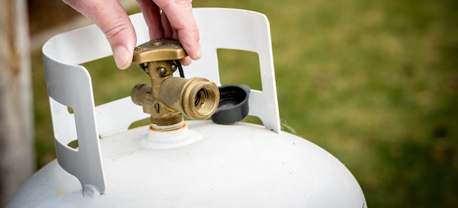
The tanks are often closed very tightly to prevent leaks. If your propane tank won’t open after you bring it home the first time, try using a wrench or a pair of pliers. You can also unhook the tank from your stove and apply a bit of oil to the valve, before trying to yank it open with pliers.
Before you try to fix a propane safety valve (or any other tank valve), you need to identify the cause of the blockage. This will determine what you need to do to correct the issue.
The most important thing to bear in mind is that propane is highly combustible. When correcting a faulty tank valve, make sure you don’t puncture the tank and cause more damage. Safety is always a priority, so work in a ventilated area and do not light matches or lighters near your tank.
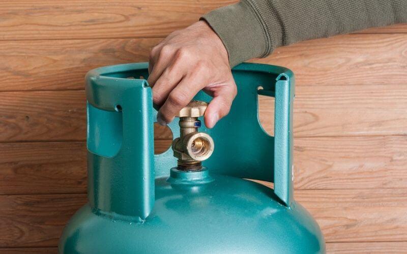
Set the propane tank on a steady, level surface. Make sure you are in a dry and cool area. Carefully check the tank for any signs of obvious damage and try to find the source of any possible leaks.
Wrap the rubber band around the outer edges of the valve to get a better grip on the blocked valve. Once you get a firm grip, twist firmly to loosen and dislodge the valve with your hand.
If this doesn’t work, spray a bit of oil or lubricant on the valve. Shake the valve back and forth to loosen it up, and then try to twist it open once again.
If the valve is still stuck, use a pair of pliers or a wrench to force it open. Grasp the edge of the valve with your pliers firmly and twist counterclockwise to open the valve. Try not to use too much pressure or as this can break the valve instead.
If your valves have rust or water damage, assess the situation. If it is still in the early stages, you can use baking soda and vinegar to get rid of the rust. However, if it is too far gone, you will need to replace the valve.
To avoid the fuss of a propane tank valve that needs to be dislodged, you can follow a few simple steps to prevent it from happening in the first place.
Don’t twist the valve closed too tightly. This might sound obvious, but people tend to close the valve really tightly, especially after a refill. Shut it tight, but don’t overdo it.
After buying a new tank or refilling your old one, smack the bottom of the tank on the ground once or twice. This will loosen the valve so you can open it more easily.
Don’t open the valve of a new cylinder rapidly as this can make it get jammed the next time. Instead, test the water and work it slowly and carefully.
If your propane tank leaks when connected, you most likely need a new valve. Check for the site of the leak by spraying soapy water at the valve, connection point, and pipes. If you see bubbles at the valve or connection, the gasket is broken and the valve requires replacing.
Soak the hose for a few minutes in warm soapy water to clean it. Use grease-cutting dish soap or something similar to break down accumulated oil and debris. Rinse the hose thoroughly under running water and allow it to dry.
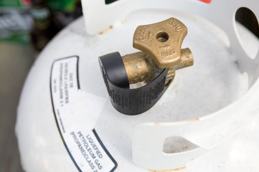
The propane tank shut-off valve is your best bet during leaks if the hose or valve isn’t the one behind the leaks. The service or shut-off valve is the metallic spigot-like dial located under the tank cover and hooked to the top of the tank.
You need to use this valve to turn the gas off at the tank in the event of an emergency or leak. Always turn this valve to the right (clockwise), completely to shut off the gas.
This kind of valve is required on all large 4-to-40-pound commercial cylinders in vapor service. The OPD valve is a protective device and is exactly what it sounds like. It prevents the tank from overfilling.
Place the open jaws of the crescent wrench over the large bolt of the tank’s gas regulator. This is located at the meeting point of the propane tank and the gas regulator. Use the thumbscrew to grip the jaws around the large nut.
Then, loosen the nut with the wrench. Continue to remove the nut by hand until you can pull the neck of the regulator from the propane tank connection. You may catch a small whiff of gas as the regulator’s neck is pulled from the propane tank, but this is nothing to be worried about.
Remove the tank from the grill’s cart. In some models, you might have to loosen a safety strap. Store the empty tank in a safe and dry location, outdoors and well away from any flames.
It is perfectly normal to smell a little propane as tiny amounts can leak when the tank is in use. You can also smell the gas when the tank is nearly empty.
It is common for a propane tank to hiss. Hearing this sound is an indication that your tank is leaking so shut off all the valves and check for the location of the leak.
It is always a little scary when dealing with gas tanks, as we are well aware of the risks. However, knowing how to handle any kind of malfunctioning will make it much easier to deal with.
Once you know how to unstick a propane tank valve, you can loosen the valve or spigot without any trouble. And this will make the process of grilling much easier. Happy cooking!

It could be the fixed liquid level gauge (bleeder valve), which is opened by the delivery person every time the tank is filled with propane. On occasion, the bleeder valve is not closed completely, whether due to driver error or debris blockage. If this is the case, simply turning the bleeder valve clockwise will close the valve and stop the flow of gas. This is not unheard of and is easily remedied by simply closing the bleeder valve. The hissing noise could also be coming from the safety relief valve. On hot days when the sun is high overhead and a propane delivery has recently been made, the safety relief valve may open slightly allowing excess pressure to vent. If the relief valve is opened, the protective cap will be removed from the top of the valve from the pressure buildup. Do not look into the relief valve or tap it with anything. Doing so may cause the relief valve to open all the way. One way to remedy the situation is to cool the tank down by spraying water from a garden hose on the surface of the tank. This will generally cause the relief valve to close. Lastly, it could be the regulator humming and the pressure needs to be readjusted. Just call our office and a technician will be happy to stop by and readjust it for you.
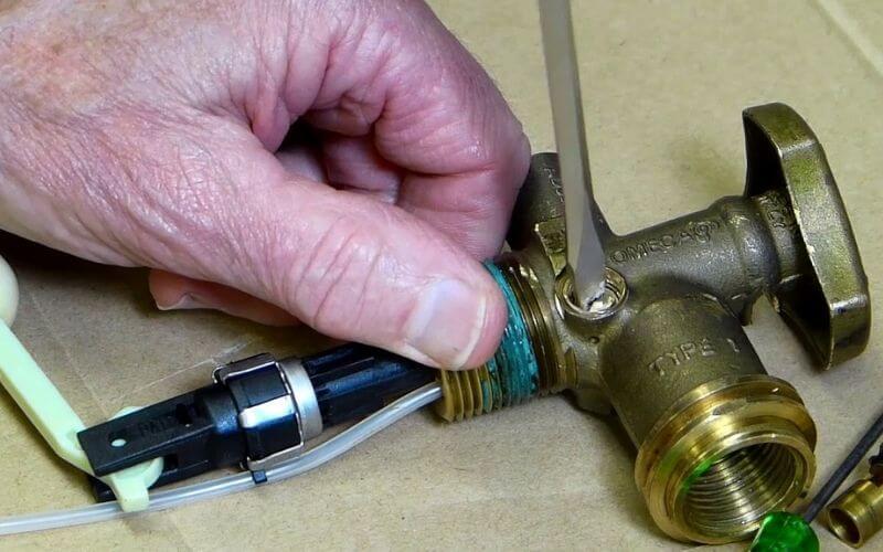
The design of the OPD valve is such that turning the cylinder service valve hand wheel will not produce any effect if the cylinder is not hooked up to an appliance. In other words, a connection must be made between the appliance hose end and the cylinders service valve. The inside of the OPD valve is engineered to only allow propane in or out if the internal valve is actuated by being depressed. This OPD valve feature adds additional safety in case the hand wheel is turned, opening the valve. For this reason, OPD equipped cylinders will not allow gas out of the cylinder when opened. The same is true for industrial forklift cylinders. Also, the hose end connection on either a fill hose or appliance supply line is designed to work only with OPD equipped cylinders. For the OPD valve to operate with the hand wheel open, the hose end connection must be securely attached. The hose end connection has an elevated brass fitting which is surrounded by acme threads. When attached to a cylinder valve and tightened, the brass fitting will push the internal valve open and allow gas to flow out of the cylinder to the appliance, if the hand wheel is in the open position. This fitting must be in place for gas to flow out of the cylinder. Otherwise, turning the hand wheel will not produce the intended result.
Freezing and frosting of propane regulators is quite common and usually nothing to be concerned about, provided everything is in working order and operating as it should. Frost can form on regulators connected to both propane cylinders and bulk (stationary) LP gas tanks. If in doubt about the safety of your regulator, turn off the tank service valve and contact your propane company. Further reading will help propane users understand the reasoning and causes of a “freezing” regulator. During normal operation propane regulators can become covered in frost, which may alarm some users. While this “freezing” of the regulator may be a symptom of a more severe problem, it’s usually is a sign that outside humidity is at a level capable of producing condensation. The only difference is, the condensation forming on a regulator is frozen. As described, propane regulators act as a barrier between high tank pressures and delivery pressure as required by downstream appliances and/or equipment. Once a propane appliance is actively in use, the liquid propane in a tank or cylinder begins to boil. The propane vapor, as boiled off the top of the liquid begins its journey downstream to the point at which it is used. Before making its way to the LP gas system piping, it passes through the regulator where its pressure is reduced to a usable level. Keep in mind that the regulator will only deliver a constant pressure on the outlet side while inlet pressures can significantly vary. As the propane passes through the regulator, it expands (resulting in sub-zero temperatures) and causes the regulator to gradually reach the extremely cold temperature of the propane vapor passing through it. Depending on the temperature and humidity of the surrounding air, the regulator will produce condensation, much like that of a frozen mug or glass taken out of a freezer. This is why, under normal operation in hot and humid climates, the external surface of a regulator will freeze and appear to be frozen or frosted. The rate at which propane is being withdrawn from the tank or cylinder will also cause the container to display a visible frost line, which indicates the liquid level of the propane within the tank. Although regulators can freeze under normal and “proper” operating conditions, there are times when regulators are freezing because of actual problems. One of the problematic issues causing a regulator to freeze is due to liquid propane entering and passing through the regulator. Liquid propane can produce an effect of extreme freezing when introduced abruptly into a regulator. There are two ways that liquid can be delivered through the tank (or cylinder) service valve: 1) If the container is overfilled or, 2) If the tank, usually a bottle, is not upright with the service valve communicating with the vapor space of the container. Both of these scenarios are possible and while avoidable, are not very common.
The only way to lock in a price is through our price protection program. Our customers who choose a variable “market” price plan cannot lock their price. These customers are charged a price based on the market price for propane on the day of delivery. That means a customer’s price on the day of delivery may be higher or lower than when they called to request the delivery. During the last heating season, propane prices started to rise, so on some days the price may be higher than when the customer called. In falling markets, our variable priced customers can potentially benefit from a lower price on the day of delivery.
Unless you are on a budget plan or have pre-paid in advance, you have 30 days from the date of delivery to make a payment. Just like any business, we also have to pay our suppliers and employees, so we appreciate payment on time. If we haven’t received payment in 30 days, we’ll send you a friendly reminder. We know that sometimes life happens – a delivery slip may be lost, or could be put in the bill drawer. If at any time you are having trouble making a payment, please call or email us and we can arrange for a payment plan. After 30 days, 1.5% interest is charged per month.
Charges resulting from interest, fuel surcharges, tax, service calls, labor, etc. are billed to the same account as your residential propane deliveries so they deduct from any credit on your account. However, your fuel credit will be replenished when payment is made for these charges.
If the tank is leased by Garrow Propane, then no. Our Garrow tanks come painted a sliver/gray color with a tan hood. If your Garrow tank is starting to rust or the paint is chipping please contact our office and we will put you on the paint list. Every summer we repaint the tanks on the list for that year. If you own the tank, you can paint it if you’d like, but not any color you choose. All too often propane customers take it upon themselves to paint their tank a color that complements the colors of their home or landscaping. This presents a safety problem as well as a serviceability problem if the tank color is dark or non-reflective. Dark colors absorb heat while lighter colors reflect it. Have you ever worn a dark colored shirt on a sunny day? A dark shirt on a sunny day will make you much warmer than a white shirt. The principle is the same with LP gas tanks, and the last thing a propane tank needs is to absorb heat. Perhaps a better example is walking barefoot on the concrete sidewalk and stepping onto an asphalt street on a hot sunny day. Concrete sidewalks are fairly light in color (heat reflective) while asphalt streets and roads are dark in color (heat absorbent). The sidewalk is much more bearable to walk on while the asphalt road can be quite painful. Propane tanks need to reflect heat, not absorb it. The entire reasoning behind propane tank color involves pressure and some simple laws of chemistry that apply to fluids and gases when they are heated. The law “as temperature increases, volume increases” applies. Because propane exists as both a liquid and a gas within the tank, the absorption of heat due to a non-reflective color creates the possibility of a high-pressure situation that may cause the safety relief valve to open. The bottom line is this: Dark (Non Reflective) Propane Tank = Absorbed Heat = Propane Expansion = Relief Valve May Open.
In its natural state, propane is an odorless gas. As a safety precaution, a chemical called Ethyl Mercaptan is added so that any presence of propane may be easily detected. The concentration level of ethyl mercaptan that is added to propane is not harmful.
No, propane is an approved, clean fuel listed in the 1990 Clean Air Act and the Energy Policy Act of 1992. Propane is one of the cleanest burning of all fossil fuels. Tests conducted by the U.S. Environmental Protection Agency show that propane-fueled vehicles produce 30-90% less carbon monoxide and about 50% fewer toxins and other smog-producing emissions than gasoline engines. Propane also is nontoxic, so it’s not harmful to soil or water. In the event of a leak, propane will dissipate into a vapor, leaving no lasting effect on the surrounding environment
Propane tanks are most commonly referred to by their water capacity volume, and propane tanks are normally filled to 80% of its water capacity. For example, a 120 gallon tank will hold approximately 100 gallons of propane when completely full. Since propane is stored in a liquid state under pressure, it needs room to expand into a vapor. This extra “room” that is in the tank allows for that expansion. Depending on the ambient temperature outside, propane may expand more or less.
Safety is a part of everything we do. We charge a hazmat fee to help us cover the costs of ensuring the safety of our customer and employees. These measures include policies, procedures, gas check training, cylinder requalification, to our own facility and vehicle operations.
When you rent a tank, Garrow Propane assumes responsibility for equipment upkeep and maintenance of your propane system, including painting the tank and replacement of first-stage regulators. You are invoiced the tank rent only if you are a low volume user as your lease agreement states. In this case your usage does NOT cover the cost of equipment Garrow Propane has provided you. Those that use the minimum amount of fuel required annually, are not invoiced a tank rent.
When you run out of propane, you will begin to smell gas. This is the mercaptan that is sitting on the bottom of the tank that is added to make propane have an odor. There is no harm in this. If you are a will-call customer, there is a pressure check charge associated with the run out. The system needs to be pressure tested and we have to ensure you ran out of fuel for lack of looking at the gauge vs. you have a gas leak.
The vaporized propane"s pressure is adjusted to between 3.5 and 5 PSI (in the case of Toyota’s). This is necessary since the fuel injector requires a precise pressure for combustion to take place
For that reason, we"ll stick to Toyota propane forklift troubleshooting in this article,focusing on the Toyota 8-Series fork trucks with 4Y engines built prior to 2020.
When a liquid propane tank is properly installed on a forklift, the fuel intake tube (in red) is pointed downward, allowing it to suck up the liquid fuel.
Additionally, cold temperatures can cause the regulator itself to freeze, which further prevents the fuel from flowing and ultimately the forklift from starting.
An example of an improperly-connected propane fuel coupler. The large space between the red tank-side coupler and the golden forklift-side coupler indicates that the quad ring has popped out of place
Those contaminants can be rust from inside of steel tanks, powder from the aluminum tank manufacturing process, paint chips, or any number of other particles.
Now that you’re aware of some of the issues with propane fuel itself, it’ll be easier to understand the role and importance of the fuel filter in a propane fuel system.
The fuel filter is a simple tube made of brass, copper, stone, or composite material that attracts contaminants from the liquid fuel that passes through it.
If you suspect that your fuel filter needs to be replaced, it’s best to call a qualified forklift technician. Because a forklift’s fuel line may contain pressurized liquid propane, changing the fuel filter can result in a release of that fuel. And if that happens, serious injury can result.
As we noted in the How Does a Propane Forklift Fuel System Work? section, the fuel solenoid acts as a “gatekeeper,” preventing or allowing fuel to flow from the fuel line into the regulator and beyond.
Fuel solenoid troubleshooting can get very complicated very quickly. So in these cases, it’s best to contact a qualified forklift technician to troubleshoot the root cause(s).
If you’re experiencing a no-start situation with your forklift, and you’ve traced it to the regulator, you should first check the various hoses and tubes going to and from the regulator.
REMINDER: Regulator maintenance should only be performed by a qualified forklift technician. Propane is extremely cold and can quickly cause serious injury if proper precautions aren’t taken.
Are all hoses to and from the regulator connected, snug, and free of any damage? (Only check when the forklift is off and the engine is cool. And make sure to follow all safety warnings and decals!)
The reason is that the regulator depends on the coolant from the radiator to prevent it from freezing as super-cooled liquid propane flows through it.

Before you go into panic mode, we’ll show you exactly how to troubleshoot this common issue and get your propane-powered appliances up and running in no time.
This diagram of an example RV propane system will help you understand where each point is within your propane system (denoted in red), which you can use as a guide to help resolve your issue.
So, if your RV propane tank is full, but there’s no gas flowing, we can simply go down the following list of causes until we identify and resolve the issue.
Even if you’re pretty sure you turned the gas valve on, go double-check. If it is indeed on and your propane is still not flowing, continue on to the next cause.
In a propane tank, this is either a spring-loaded valve or ball which detects whether the gas inside is coming out too quickly. If it senses that this is happening, then it engages and stops the flow of gas.
Opening the RV propane tank valve too quickly can cause it to sense a leak. In other words, it will register a higher volume of propane flowing from the tank than would normally be expected and engage in “emergency mode” as a result.
Important: The excess flow valve could be engaged because of a leak. Ensure that there are no leaks in your RV propane system. If you don’t feel comfortable checking for and repairing propane leaks yourself, take your motorhome to a repair shop.
An RV propane regulator regulates the pressure of the propane gas coming from the propane tank. In other words, high-pressure gas flowing from your tank will go through your regulator, which lowers it to the proper level to be used by your propane-powered appliances.
As you can see in the diagram above, the regulator sits between the RV’s propane tank and the rest of the system. This is the same whether you have two propane tanks, or just one.
RV Propane regulators have a 10-15 year lifespan. So, if your pressure regulator is reaching that point, it’s time to swap it out for a new one. They are extremely easy to install and inexpensive. Check out our RV propane regulator guide to find the best option for your RV.
Tip: You could also try to reset your propane regulator, which technically you already did if you followed the troubleshooting steps for the excess flow valve. Shut off the propane tank valve, turn off any propane-powered appliances, wait a few minutes, then slowly turn the propane tank valve back on.
The hose from the propane tank to the regulator can also cause the propane to stop flowing. In some cases, this hose will have a back check valve that can get stuck, thus restricting the propane flow.
This is a great feature to have. But if power is cut to the propane detector (or the solenoid that controls the propane supply), the propane will not be able to flow.
This is usually due to a dead battery or faulty wiring. So, check your battery and check to make sure power is going to the detector and solenoid. You should frequently test your RV propane detector to ensure it’s in good working condition.
If you use a gas grill, heat your home or spend time in an industrial facility, chances are you have used propane. It’s a well-established gas for many uses, but it can be dangerous.
Below are some rules to practice safety in the household and the workplace by following regulations set by the Occupational Safety and Health Administration (OSHA) and the Compressed Gas Association.
Cylinders used for forklifts can be stored in either the vertical or horizontal position. If stored horizontally, the relief valve must be positioned at 12 o’clock. These cylinders do not require an overfill prevention device (OPD).
Risk Managers and Safety Directors: If you would like to schedule an introductory call with an Oswald professional fill out the form below or learn more about Oswald Risk Consulting: Safety & Loss Control services.
Oswald OnTrack is a secure, web-based risk management and safety platform designed toease compliance, improve risk prevention efforts and results, and relieve regulatory pain points for any industry. The programs are simple to set up and easily create a comprehensive and cost-effective risk management and safety program that can be utilized by all departments.
Oswald OnTrack, powered by Succeed Management Solutions, enables the oversight and management of multiple locations and departments, making it a perfect resource for the safety-conscious organization.
Note: This communication is for informational purposes only.Although every reasonable effort is made to present current and accurate information, Oswald makes no guarantees of any kind and cannot be held liable for any outdated or incorrect information. View our communications policy.

Container assembly - An assembly consisting essentially of the container and fittings for all container openings, including shutoff valves, excess flow valves, liquid-level gaging devices, safety relief devices, and protective housing.
“Liquified petroleum gases” - “LPG” and “LP-Gas” - Any material which is composed predominantly of any of the following hydrocarbons, or mixtures of them; propane, propylene, butanes (normal butane or iso-butane), and butylenes.
Movable fuel storage tenders or farm carts - Containers not in excess of 1,200 gallons water capacity, equipped with wheels to be towed from one location of usage to another. They are basically nonhighway vehicles, but may occasionally be moved over public roads or highways. They are used as a fuel supply for farm tractors, construction machinery and similar equipment.
Systems - an assembly of equipment consisting essentially of the container or containers, major devices such as vaporizers, safety relief valves, excess flow valves, regulators, and piping connecting such parts.
Vaporizer-burner - an integral vaporizer-burner unit, dependent upon the heat generated by the burner as the source of heat to vaporize the liquid used for dehydrators or dryers.
Ventilation, adequate - when specified for the prevention of fire during normal operation, ventilation shall be considered adequate when the concentration of the gas in a gas-air mixture does not exceed 25 percent of the lower flammable limit.
Approved - unless otherwise indicated, listing or approval by a nationally recognized testing laboratory. Refer to § 1910.7 for definition of nationally recognized testing laboratory.
All liquefied petroleum gases shall be effectively odorized by an approved agent of such character as to indicate positively, by distinct odor, the presence of gas down to concentration in air of not over one-fifth the lower limit of flammability. Odorization, however, is not required if harmful in the use of further processing of the liquefied petroleum gas, or if odorization will serve no useful purpose as a warning agent in such use or further processing.
The odorization requirement of paragraph (b)(1)(i) of this section shall be considered to be met by the use of 1.0 pounds of ethyl mercaptan, 1.0 pounds of thiophane or 1.4 pounds of amyl mercaptan per 10,000 gallons of LP-Gas. However, this listing of odorants and quantities shall not exclude the use of other odorants that meet the odorization requirements of paragraph (b)(1)(i) of this section.
Each system utilizing DOT containers in accordance with 49 CFR part 178 shall have its container valves, connectors, manifold valve assemblies, and regulators approved.
Each system for domestic or commercial use utilizing containers of 2,000 gallons or less water capacity, other than those constructed in accordance with 49 CFR part 178, shall consist of a container assembly and one or more regulators, and may include other parts. The system as a unit or the container assembly as a unit, and the regulator or regulators, shall be individually listed.
In systems utilizing containers of over 2,000 gallons water capacity, each regulator, container valve, excess flow valve, gaging device, and relief valve installed on or at the container, shall have its correctness as to design, construction, and performance determined by listing by a nationally recognized testing laboratory. Refer to § 1910.7 for definition of nationally recognized testing laboratory.
Containers used with systems embodied in paragraphs (d), (e), (g), and (h) of this section, except as provided in paragraphs (e)(3)(iii) and (g)(2)(i) of this section, shall be designed, constructed, and tested in accordance with the Rules for Construction of Unfired Pressure Vessels, section VIII, Division 1, American Society of Mechanical Engineers (ASME) Boiler and Pressure Vessel Code, 1968 edition, which is incorporated by reference as specified in § 1910.6.
Containers constructed according to the 1949 and earlier editions of the ASME Code do not have to comply with paragraphs U-2 through U-10 and U-19 thereof. Containers constructed according to paragraph U-70 in the 1949 and earlier editions are not authorized.
Containers designed, constructed, and tested prior to July 1, 1961, according to the Code for Unfired Pressure Vessels for Petroleum Liquids and Gases, 1951 edition with 1954 Addenda, of the American Petroleum Institute and the American Society of Mechanical Engineers, which is incorporated by reference as specified in § 1910.6, shall be considered in conformance. Containers constructed according to API-ASME Code do not have to comply with section I or with appendix to section I. Paragraphs W-601 to W-606 inclusive in the 1943 and earlier editions do not apply.
The provisions of paragraph (b)(3)(i) of this section shall not be construed as prohibiting the continued use or reinstallation of containers constructed and maintained in accordance with the standard for the Storage and Handling of Liquefied Petroleum Gases NFPA No. 58 in effect at the time of fabrication.
Containers used with systems embodied in paragraph (b), (d)(3)(iii), and (f) of this section, shall be constructed, tested, and stamped in accordance with DOT specifications effective at the date of their manufacture.
Welding to the shell, head, or any other part of the container subject to internal pressure, shall be done in compliance with the code under which the tank was fabricated. Other welding is permitted only on saddle plates, lugs, or brackets attached to the container by the tank manufacturer.
Where repair or modification involving welding of DOT containers is required, the container shall be returned to a qualified manufacturer making containers of the same type, and the repair or modification made in compliance with DOT regulations.
Each container covered in paragraph (b)(3)(i) of this section, except as provided in paragraph (b)(3)(iv) of this section shall be marked as specified in the following:
With a marking identifying compliance with, and other markings required by, the rules of the reference under which the container is constructed; or with the stamp and other markings required by the National Board of Boiler and Pressure Vessel Inspectors.
With notation as to whether the container is designed for underground or aboveground installation or both. If intended for both and different style hoods are provided, the marking shall indicate the proper hood for each type of installation.
With the wording “This container shall not contain a product having a vapor pressure in excess of __ p.s.i.g. at 100 °F.,” see subparagraph (14)(viii) of this paragraph.
With marking indicating the maximum level to which the container may be filled with liquid at temperatures between 20 °F. and 130 °F., except on containers provided with fixed maximum level indicators or which are filled by weighing. Markings shall be increments of not more than 20 °F. This marking may be located on the liquid level gaging device.
Markings specified shall be on a metal nameplate attached to the container and located in such a manner as to remain visible after the container is installed.
When LP-Gas and one or more other gases are stored or used in the same area, the containers shall be marked to identify their content. Marking shall conform to the marking requirements set forth in § 1910.253(b)(1)(ii).
In the case of buildings devoted exclusively to gas manufacturing and distributing operations, the distances required by Table H-23 may be reduced provided that in no case shall containers of water capacity exceeding 500 gallons be located closer than 10 feet to such gas manufacturing and distributing buildings.
The minimum separation between liquefied petroleum gas containers and flammable liquid tanks shall be 20 feet, and the minimum separation between a container and the centerline of the dike shall be 10 feet. The foregoing provision shall not apply when LP-Gas containers of 125 gallons or less capacity are installed adjacent to Class III flammable liquid tanks of 275 gallons or less capacity.
Suitable means shall be taken to prevent the accumulation of flammable liquids under adjacent liquified petroleum gas containers, such as by diking, diversion curbs, or grading.
Valves, fittings, and accessories connected directly to the container including primary shutoff valves, shall have a rated working pressure of at least 250 p.s.i.g. and shall be of material and design suitable for LP-Gas service. Cast iron shall not be used for container valves, fittings, and accessories. This does not prohibit the use of container valves made of malleable or nodular iron.
Connections to containers, except safety relief connections, liquid level gaging devices, and plugged openings, shall have shutoff valves located as close to the container as practicable.
Excess flow valves, where required shall close automatically at the rated flows of vapor or liquid as specified by the manufacturer. The connections or line including valves, fittings, etc., being protected by an excess flow valve shall have a greater capacity than the rated flow of the excess flow valve.
Liquid level gaging devices which are so constructed that outward flow of container contents shall not exceed that passed by a No. 54 drill size opening, need not be equipped with excess flow valves.
Openings from container or through fittings attached directly on container to which pressure gage connection is made, need not be equipped with shutoff or excess flow valves if such openings are restricted to not larger than No. 54 drill size opening.
Except as provided in paragraph (c)(5)(i)(b) of this section, excess flow and back pressure check valves where required by this section shall be located inside of the container or at a point outside where the line enters the container; in the latter case, installation shall be made in such manner that any undue strain beyond the excess flow or back pressure check valve will not cause breakage between the container and such valve.
Containers of more than 30 gallons water capacity and less than 2,000 gallons water capacity, filled on a volumetric basis, and manufactured after December 1, 1963, shall be equipped for filling into the vapor space.
Pipe, except as provided in paragraphs (e)(6)(i) and (g)(10)(iii), of this section shall be wrought iron or steel (black or galvanized), brass, copper, or aluminum alloy. Aluminum alloy pipe shall be at least Schedule 40 in accordance with the specifications for Aluminum Alloy Pipe, American National Standards Institute (ANSI) H38.7-1969 (ASTM, B241-69), which is incorporated by reference as specified in § 1910.6, except that the use of alloy 5456 is prohibited and shall be suitably marked at each end of each length indicating compliance with American National Standard Institute Specifications. Aluminum Alloy pipe shall be protected against external corrosion when it is in contact with dissimilar metals other than galvanized steel, or its location is subject to repeated wetting by such liquids as water (except rain water), detergents, sewage, or leaking from other piping, or it passes through flooring, plaster, masonry, or insulation. Galvanized sheet steel or pipe, galvanized inside and out, may be considered suitable protection. The maximum nominal pipe size for aluminum pipe shall be three-fourths inch and shall not be used for pressures exceeding 20 p.s.i.g. Aluminum alloy pipe shall not be installed within 6 inches of the ground.
Tubing shall be seamless and of copper, brass, steel, or aluminum alloy. Copper tubing shall be of type K or L or equivalent as covered in the Specification for Seamless Copper Water Tube, ANSI H23.1-1970 (ASTM B88-69), which is incorporated by reference as specified in § 1910.6. Aluminum alloy tubing shall be of Type A or B or equivalent as covered in Specification ASTM B210-68 (which is incorporated by reference as specified in § 1910.6) and shall be suitably marked every 18 inches indicating compliance with ASTM Specifications. The minimum nominal wall thickness of copper tubing and aluminum alloy tubing shall be as specified in Table H-24 and Table H-25.
Aluminum alloy tubing shall be protected against external corrosion when it is in contact with dissimilar metals other than galvanized steel, or its location is subject to repeated wetting by liquids such as water (except rainwater), detergents, sewage, or leakage from other piping, or it passes through flooring, plaster, masonry, or insulation. Galvanized sheet steel or pipe, galvanized inside and out, may be considered suitable protection. The maximum outside diameter for aluminum alloy tubing shall be three-fourths inch and shall not be used for pressures exceeding 20 p.s.i.g. Aluminum alloy tubing shall not be installed within 6 inches of the ground.
In systems where the gas in liquid form without pressure reduction enters the building, only heavy walled seamless brass or copper tubing with an internal diameter not greater than three thirty-seconds inch, and a wall thickness of not less than three sixty-fourths inch shall be used. This requirement shall not apply to research and experimental laboratories, buildings, or separate fire divisions of buildings used exclusively for housing internal combustion engines, and to commercial gas plants or bulk stations where containers are charged, nor to industrial vaporizer buildings, nor to buildings, structures, or equipment under construction or undergoing major renovation.
Pipe joints may be screwed, flanged, welded, soldered, or brazed with a material having a melting point exceeding 1,000 °F. Joints on seamless copper, brass, steel, or aluminum alloy gas tubing shall be made by means of approved gas tubing fittings, or soldered or brazed with a material having a melting point exceeding 1,000 °F.
The use of threaded cast iron pipe fittings such as ells, tees, crosses, couplings, and unions is prohibited. Aluminum alloy fittings shall be used with aluminum alloy pipe and tubing. Insulated fittings shall be used where aluminum alloy pipe or tubing connects with a dissimilar metal.
Strainers, regulators, meters, compressors, pumps, etc., are not to be considered as pipe fittings. This does not prohibit the use of malleable, nodular, or higher strength gray iron for such equipment.
All materials such as valve seats, packing, gaskets, diaphragms, etc., shall be of such quality as to be resistant to the action of liquefied petroleum gas under the service conditions to which they are subjected.
All piping, tubing, or hose shall be tested after assembly and proved free from leaks at not less than normal operating pressures. After installation, piping and tubing of all domestic and commercial systems shall be tested and proved free of leaks using a manometer or equivalent device that will indicate a drop in pressure. Test shall not be made with a flame.
Provision shall be made to compensate for expansion, contraction, jarring, and vibration, and for settling. This may be accomplished by flexible connections.
Piping outside buildings may be buried, above ground, or both, but shall be well supported and protected against physical damage. Where soil conditions warrant, all piping shall be protected against corrosion. Where condensation may occur, the piping shall be pitched back to the container, or suitable means shall be provided for revaporization of the condensate.
Hose shall be fabricated of materials that are resistant to the action of LP-Gas in the liquid and vapor phases. If wire braid is used for reinforcing the hose, it shall be of corrosion-resistant material such as stainless steel.
Hose subject to container pressure shall have its correctness as to design construction and performance determined by being listed (see § 1910.110(a)(15)).
Hose and hose connections on the low-pressure side of the regulator or reducing valve shall be designed for a bursting pressure of not less than 125 p.s.i.g. or five times the set pressure of the relief devices protecting that portion of the system, whichever is higher.
Hose may be used on the low-pressure side of regulators to connect to other than domestic and commercial gas appliances under the following conditions:
For use inside buildings the hose shall be of minimum practical length, but shall not exceed 6 feet except as provided in paragraph (c)(5)(i)(g) of this section and shall not extend from one room to another, nor pass through any walls, partitions, ceilings, or floors. Such hose shall not be concealed from view or used in a concealed location. For use outside of buildings, the hose may exceed this length but shall be kept as short as practical.
The hose shall be approved and shall not be used where it is likely to be subjected to temperatures above 125 °F. The hose shall be securely connected to the appliance and the use of rubber slip ends shall not be permitted.
The shutoff valve for an appliance connected by hose shall be in the metal pipe or tubing and not at the appliance end of the hose. When shutoff valves are installed close to each other, precautions shall be taken to prevent operation of the wrong valve.
Every container except those constructed in accordance with DOT specifications and every vaporizer (except motor fuel vaporizers and except vaporizers described in paragraph (b)(11)(ii)(c) of this section and paragraph (d)(4)(v)(a) of this section) whether heated by artificial means or not, shall be provided with one or more safety relief valves of spring-loaded or equivalent type. These valves shall be arranged to afford free vent to the outer air with discharge not less than 5 feet horizontally away from any opening into the building which is below such discharge. The rate of discharge shall be in accordance with the requirements of paragraph (b)(10)(ii) or (b)(10)(iii) of this section in the case of vaporizers.
Minimum required rate of discharge in cubic feet per minute of air at 120 percent of the maximum permitted start to discharge pressure for safety relief valves to be used on containers other than those constructed in accordance with DOT specification shall be as follows:
When the surface area is not stamped on the nameplate or when the marking is not legible, the area can be calculated by using one of the following formulas:
The rate of discharge may be interpolated for intermediate values of surface area. For containers with total outside surface area greater than 2,000 square feet, the required flow rate can be calculated using the formula, Flow Rate-CFM Air = 53.632 A0.82.
Valves not marked “Air” have flow rate marking in cubic feet per minute of liquefied petroleum gas. These can be converted to ratings in cubic feet per minute of air by multiplying the liquefied petroleum gas ratings by factors listed below. Air flow ratings can be converted to ratings in cubic feet per minute of liquefied petroleum gas by dividing the air ratings by the factors listed below.
Obtain the total surface area by adding the surface area of vaporizer shell in square feet directly in contact with LP-Gas and the heat exchanged surface area in square feet directly in contact with LP-Gas.
Obtain the minimum required rate of discharge in cubic feet of air per minute, at 60 °F. and 14.7 p.s.i.a. from paragraph (b)(10)(ii) of this section, for this total surface area.
Container and vaporizer safety relief valves shall be set to start-to-discharge, with relation to the design pressure of the container, in accordance with Table H-26.
Safety relief devices used with systems employing containers other than those constructed according to DOT specifications shall be so constructed as to discharge at not less than the rates shown in paragraph (b)(10)(ii) of this section, before the pressure is in excess of 120 percent of the maximum (not including the 10 percent referred to in paragraph (b)(10)(iv) of this section) permitted start to discharge pressure setting of the device.
In certain locations sufficiently sustained high temperatures prevail which require the use of a lower vapor pressure product to be stored or the use of a higher designed pressure vessel in order to prevent the safety valves opening as the result of these temperatures. As an alternative the tanks may be protected by cooling devices such as by spraying, by shading, or other effective means.
Safety relief valves shall be arranged so that the possibility of tampering will be minimized. If pressure setting or adjustment is external, the relief valves shall be provided with approved means for sealing adjustment.
Shutoff valves shall not be installed between the safety relief devices and the container, or the equipment or piping to which the safety relief device is connected except that a shutoff valve may be used where the arrangement of this valve is such that full required capacity flow through the safety relief device is always afforded.
Each container safety relief valve used with systems covered by paragraphs (d), (e), (g), and (h) of this section, except as provided in paragraph (e)(3)(iii) of this section shall be plainly and permanently marked with the following: “Container Type” of the pressure vessel on which the valve is designed to be installed; the pressure in p.s.i.g. at which the valve is set to discharge; the actual rate of discharge of the valve in cubic feet per minute of air at 60 °F. and 14.7 p.s.i.a.; and the manufacturer"s name and catalog number, for example: T200-250-4050 AIR - indicating that the valve is suitable for use on a Type 200 container, that it is set to start to discharge at 250 p.s.i.g.; and that its rate of discharge is 4,050 cubic feet per minute of air as determined in subdivision (ii) of this subparagraph.
Safety relief valve assemblies, including their connections, shall be of sufficient size so as to provide the rate of flow required for the container on which they are installed.
A hydrostatic relief valve shall be installed between each pair of shut-off valves on liquefied petroleum gas liquid piping so as to relieve into a safe atmosphere. The start-to-discharge pressure setting of such relief valves shall not be in excess of 500 p.s.i.g. The minimum setting on relief valves installed in piping connected to other than DOT containers shall not be lower than 140 percent of the container relief valve setting and in piping connected to DOT containers not lower than 400 p.s.i.g. The start-to-discharge pressure setting of such a relief valve, if installed on the discharge side of a pump, shall be greater than the maximum pressure permitted by the recirculation device in the system.
The discharge from any safety relief device shall not terminate in or beneath any building, except relief devices covered by paragraphs (b)(6)(i) (a) through (e) of this section, or paragraphs (c) (4)(i) or (5) of this section.
Container safety relief devices and regulator relief vents shall be located not less than five (5) feet in any direction from air openings into sealed combustion system appliances or mechanical ventilation air intakes.
Vaporizers shall be constructed in accordance with the requirements of paragraph (b)(3) (i)-(iii) of this section and shall be permanently marked as follows:
Vaporizers having an inside diameter of 6 inches or less exempted by the ASME Unfired Pressure Vessel Code, Section VIII of the ASME Boiler and Pressure Vessel Code - 1968 shall have a design pressure not less than 250 p.s.i.g. and need not be permanently marked.
Vaporizers may be installed in buildings, rooms, sheds, or lean-tos used exclusively for gas manufacturing or distribution, or in other structures of light, noncombustible construction or equivalent, well ventilated near the floor line and roof.
When vaporizing and/or mixing equipment is located in a structure or building not used exclusively for gas manufacturing or distribution, either attached to or within such a building, such structure or room shall be separated from the remainder of the building by a wall designed to withstand a static pressure of at least 100 pounds per square foot. This wall shall have no openings or pipe or conduit passing through it. Such structure or room shall be provided with adequate ventilation and shall have a roof or at least one exterior wall of lightweight construction.
Vaporizers shall have, at or near the discharge, a safety relief valve providing an effective rate of discharge in accordance with paragraph (b)(10)(iii) of this section, except as provided in paragraph (d)(4)(v)(a), of this section.
The heating medium lines into and leaving the vaporizer shall be provided with suitable means for preventing the flow of gas into the heat systems in the event of tube rupture in the vaporizer. Vaporizers shall be provided with suitable automatic means to prevent liquid passing through the vaporizers to the gas discharge piping.
The device that supplies the necessary heat for producing steam, hot water, or other heating medium may be installed in a building, compartment, room, or lean-to which shall be ventilated near the floorline and roof to the outside. The device location shall be separated from all compartments or rooms containing liquefied petroleum gas vaporizers, pumps, and central gas mixing devices by a wall designed to withstand a static pressure of at least 100 pounds per square foot. This wall shall have no openings or pipes or conduit passing through it. This requirement does not apply to the domestic water heaters which may supply heat for a vaporizer in a domestic system.
Gas-fired heating systems supplying heat exclusively for vaporization purposes shall be equipped with automatic safety devices to shut off the flow of gas to main burners, if the pilot light should fail.
Vaporizers of less than 1 quart capacity heated by the ground or surrounding air, need not be equipped with safety relief valves provided that adequate tests demonstrate that the assembly is safe without safety relief valves.
In accordance with the requirements of the American Society of Mechanical Engineers Boiler and Pressure Vessel Code - 1968 that are applicable to the maximum working conditions for which the vaporizer is designed.
With the name of the manufacturer; rated BTU input to the burner; the area of the heat exchange surface in square feet; the outside surface of the vaporizer in square feet; and the maximum vaporizing capacity in gallons per hour.
Vaporizers may be connected to the liquid section or the gas section of the storage container, or both; but in any case there shall be at the container a manually operated valve in each connection to permit completely shutting off when desired, of all flow of gas or liquid from container to vaporizer.
Vaporizers with capacity not exceeding 35 gallons per hour shall be located at least 5 feet from container shutoff valves. Vaporizers having capacity of more than 35 gallons but not exceeding 100 gallons per hour shall be located at least 10 feet from the container shutoff valves. Vaporizers having a capacity greater than 100 gallons per hour shall be located at least 15 feet from container shutoff valves.
Vaporizers may be installed in buildings, rooms, housings, sheds, or lean-tos used exclusively for vaporizing or mixing of liquefied petroleum gas. Vaporizing housing structures shall be of noncombustible construction, well ventilated near the floorline and the highest point of the roof. When vaporizer and/or mixing equipment is located in a structure or room attached to or within a building, such structure or room shall be separated from the remainder of the building by a wall designed to withstand a static pressure of at least 100 pounds per square foot. This wall shall have no openings or pipes or conduit passing through it. Such structure or room shall be provided with adequate ventilation, and shall have a roof or at least one exterior wall of lightweight construction.
Vaporizers shall have at or near the discharge, a safety relief valve providing an effective rate of discharge in accordance with paragraph (b)(10)(iii) of this section. The relief valve shall be so located as not to be subjected to temperatures in excess of 140 °F.
Vaporizers shall be equipped with automatic safety devices to shut off the flow of gas to main burners if the pilot light should fail. When the flow through the pilot exceeds 2,000 B.t.u. per hour, the pilot also shall be equipped with an automatic safety device to shut off the flow of gas to the pilot should the pilot flame be extinguished.
Pressure regulating and pressure reducing equipment if located within 10 feet of a direct fire vaporizer shall be separated from the open flame by a substantially airtight noncombustible partition or partitions.
Except as provided in (c) of this subdivision, the following minimum distances shall be maintained between direct fired vaporizers and the nearest important building or group of buildings:
Direct fired vaporizers shall not raise the product pressure above the design pressure of the vaporizer equipment nor shall they raise the product pressure within the storage container above the pressure shown in the second column of Table H-31.
Tank heaters shall be permanently marked with the name of the manufacturer, the rated B.t.u. input to the burner, and the maximum vaporizing capacity in gallons per hour.
Tank heaters shall be equipped with an automatic safety device to shut off the flow of gas to main burners, if the pilot light should fail. When flow through pilot exceeds 2,000 B.t.u. per hour, the pilot also shall be equipped with an automatic safety device to shut off the flow of gas to the pilot should the pilot flame be extinguished.
Pressure regulating and pressure reducing equipment if located within 10 feet of a direct fired tank heater shall be separated from the open flame by a substantially airtight noncombustible partition.
The following minimum distances shall be maintained between a storage tank heated by a direct fired tank heater and the nearest important building or group of buildings:
No direct fired tank heater shall raise the product pressure within the storage container over 75 percent of the pressure set out in the second column of Table H-31.
The vaporizer section of vaporizer-burners used for dehydrators or dryers shall be located outside of buildings; they shall be constructed and installed as follows:
The vaporizer section of vaporizer-burners shall be protected by a hydrostatic relief valve. The relief valve shall be located so as not to be subjected to temperatures in excess of 140 °F. The start-to-discharge pressure setting shall be such as to protect the components involved, but not less than 250 p.s.i.g. The discharge shall be directed upward and away from component parts of the equipment and away from operating personnel.
Vaporizer-burners shall be equipped with automatic safety devices to shut off the flow of gas to the main burner and pilot in the event the pilot is extinguished.
Pressure regulating and control equipment shall be located or protected so that the temperatures surrounding this equipment shall not exceed 140 °F. except that equipment components may be used at higher temperatures if designed to withstand such temperatures.
Pressure regulating and control equipment when located downstream of the vaporizer shall be designed to withstand the maximum discharge temperature of the vapor.
Equipment utilizing vaporizer-burners shall be equipped with automatic shutoff devices upstream and downstream of the vaporizer section connected so as to operate in the event of excessive temperature, flame failure, and, if applicable, insufficient airflow.
The “filling density” is defined as the percent ratio of the weight of the gas in a container to the weight of water the container will hold at 60 °F. All containers shall be filled according to the filling densities shown in Table H-27.
Except as provided in paragraph (b)(12)(iii) of this section, any container including mobile cargo tanks and portable tank containers regardless of size or construction, shipped under DOT jurisdiction or constructed in accordance with 49 CFR chapter I Specifications shall be charged according to 49 CFR chapter I requirements.
Portable containers not subject to DOT jurisdiction (such as, but not limited to, motor fuel containers on industrial and lift trucks, and farm tractors covered in paragraph (e) of this section, or containers recharged at the installation) may be filled either by weight, or by volume using a fixed length dip tube gaging device.
are used excusively to house equipment for vaporization, pressure reduction, gas mixing, gas manufacturing, or distribution, or to house internal combustion engines, industrial processes, research and experimental laboratories, or equipment and processes using such gas and having similar hazard;
Buildings, or separate areas of buildings, used exclusively to house equipment for vaporization, pressure reduction, gas mixing, gas manufacturing, or distribution, or to house internal combustion engines, industrial processes, research and experimental laboratories, or equipment and processes using such gas and having similar hazard; and when such buildings, or separate areas thereof are constructed in accordance with this section.
Liquid piping inside the building shall conform to the requirements of paragraph (b)(8) of this section, and shall not exceed three-fourths iron pipe size. Copper tubing with an outside diameter of three-fourths inch or less may be used provided it conforms to Type K of Specifications for Seamless Water Tube, ANSI H23.1-1970 (ASTM B88-69) (see Table H-24). All such piping shall be protected against construction hazards. Liquid piping inside buildings shall be kept to a minimum. Such piping shall be securely fastened to walls or other surfaces so as to provide adequate protection from breakage and so located as to subject the liquid line to lowest ambient temperatures.
A shutoff valve shall be installed in each intermediate branch line where it takes off the main line and shall be readily accessible. A shutoff valve shall also be placed at the appliance end of the intermediate branch line. Such shutoff valve shall be upstream of any flexible connector used with the appliance.
Suitable excess flow valves shall be installed in the container outlet line supplying liquid LP-Gas to the building. A suitable excess flow valve shall be installed immediately downstream of each shutoff valve. Suitable excess flow valves shall be installed where piping size is reduced and shall be sized for the reduced size piping.
The use of hose to carry liquid between the container and the building or at any point in the liquid line, except at the appliance connector, shall be prohibited.
Where flexible connectors are necessary for appliance installation, such connectors shall be as short as practicable and shall comply with paragraph (b)(8)(ii) or (9) of this section.
at least one attendant shall remain close to the transfer connection from the time the connections are first made until they are finally disconnected, during the transfer of the product.
Containers manufactured in accordance with specifications of 49 CFR part 178 and authorized by 49 CFR chapter 1 as a "single trip" or "nonrefillable container" shall not be refilled or reused in LP-Gas service.
Gas or liquid shall not be vented to the atmosphere to assist in transferring contents of one container to another, except as provided in paragraph (e)(5)(iv) of this section and except that this shall not preclude the use of listed pump utilizing LP-Gas in the vapor phase as a source of energy and venting such gas to the atmosphere at a rate not to exceed that from a No. 31 drill size opening and provided that such venting and liquid transfer shall be located not less than 50 feet from the nearest important building.
Filling of fuel containers for industrial trucks or motor vehicles from industrial bulk storage containers shall be performed not less than 10 feet from the nearest important masonry-walled building or not less than 25 feet from the nearest important building or other construction and, in any event, not less than 25 feet from any building opening.
Filling of portable containers, containers mounted on skids, fuel containers on farm tractors, or similar applications, from storage containers used in domestic or commercial service, shall be performed no


 8613371530291