
how to set safety valve pressure in stock
In order to ensure that the maximum allowable accumulation pressure of any system or apparatus protected by a safety valve is never exceeded, careful consideration of the safety valve’s position in the system has to be made. As there is such a wide range of applications, there is no absolute rule as to where the valve should be positioned and therefore, every application needs to be treated separately.
A common steam application for a safety valve is to protect process equipment supplied from a pressure reducing station. Two possible arrangements are shown in Figure 9.3.3.
The safety valve can be fitted within the pressure reducing station itself, that is, before the downstream stop valve, as in Figure 9.3.3 (a), or further downstream, nearer the apparatus as in Figure 9.3.3 (b). Fitting the safety valve before the downstream stop valve has the following advantages:
• The safety valve can be tested in-line by shutting down the downstream stop valve without the chance of downstream apparatus being over pressurised, should the safety valve fail under test.
• When setting the PRV under no-load conditions, the operation of the safety valve can be observed, as this condition is most likely to cause ‘simmer’. If this should occur, the PRV pressure can be adjusted to below the safety valve reseat pressure.
Indeed, a separate safety valve may have to be fitted on the inlet to each downstream piece of apparatus, when the PRV supplies several such pieces of apparatus.
• If supplying one piece of apparatus, which has a MAWP pressure less than the PRV supply pressure, the apparatus must be fitted with a safety valve, preferably close-coupled to its steam inlet connection.
• If a PRV is supplying more than one apparatus and the MAWP of any item is less than the PRV supply pressure, either the PRV station must be fitted with a safety valve set at the lowest possible MAWP of the connected apparatus, or each item of affected apparatus must be fitted with a safety valve.
• The safety valve must be located so that the pressure cannot accumulate in the apparatus viaanother route, for example, from a separate steam line or a bypass line.
It could be argued that every installation deserves special consideration when it comes to safety, but the following applications and situations are a little unusual and worth considering:
• Fire - Any pressure vessel should be protected from overpressure in the event of fire. Although a safety valve mounted for operational protection may also offer protection under fire conditions,such cases require special consideration, which is beyond the scope of this text.
• Exothermic applications - These must be fitted with a safety valve close-coupled to the apparatus steam inlet or the body direct. No alternative applies.
• Safety valves used as warning devices - Sometimes, safety valves are fitted to systems as warning devices. They are not required to relieve fault loads but to warn of pressures increasing above normal working pressures for operational reasons only. In these instances, safety valves are set at the warning pressure and only need to be of minimum size. If there is any danger of systems fitted with such a safety valve exceeding their maximum allowable working pressure, they must be protected by additional safety valves in the usual way.
In order to illustrate the importance of the positioning of a safety valve, consider an automatic pump trap (see Block 14) used to remove condensate from a heating vessel. The automatic pump trap (APT), incorporates a mechanical type pump, which uses the motive force of steam to pump the condensate through the return system. The position of the safety valve will depend on the MAWP of the APT and its required motive inlet pressure.
This arrangement is suitable if the pump-trap motive pressure is less than 1.6 bar g (safety valve set pressure of 2 bar g less 0.3 bar blowdown and a 0.1 bar shut-off margin). Since the MAWP of both the APT and the vessel are greater than the safety valve set pressure, a single safety valve would provide suitable protection for the system.
However, if the pump-trap motive pressure had to be greater than 1.6 bar g, the APT supply would have to be taken from the high pressure side of the PRV, and reduced to a more appropriate pressure, but still less than the 4.5 bar g MAWP of the APT. The arrangement shown in Figure 9.3.5 would be suitable in this situation.
Here, two separate PRV stations are used each with its own safety valve. If the APT internals failed and steam at 4 bar g passed through the APT and into the vessel, safety valve ‘A’ would relieve this pressure and protect the vessel. Safety valve ‘B’ would not lift as the pressure in the APT is still acceptable and below its set pressure.
It should be noted that safety valve ‘A’ is positioned on the downstream side of the temperature control valve; this is done for both safety and operational reasons:
Operation - There is less chance of safety valve ‘A’ simmering during operation in this position,as the pressure is typically lower after the control valve than before it.
Also, note that if the MAWP of the pump-trap were greater than the pressure upstream of PRV ‘A’, it would be permissible to omit safety valve ‘B’ from the system, but safety valve ‘A’ must be sized to take into account the total fault flow through PRV ‘B’ as well as through PRV ‘A’.
A pharmaceutical factory has twelve jacketed pans on the same production floor, all rated with the same MAWP. Where would the safety valve be positioned?
One solution would be to install a safety valve on the inlet to each pan (Figure 9.3.6). In this instance, each safety valve would have to be sized to pass the entire load, in case the PRV failed open whilst the other eleven pans were shut down.
If additional apparatus with a lower MAWP than the pans (for example, a shell and tube heat exchanger) were to be included in the system, it would be necessary to fit an additional safety valve. This safety valve would be set to an appropriate lower set pressure and sized to pass the fault flow through the temperature control valve (see Figure 9.3.8).

When you’re in the market for a pressure relief valve, a sales rep has probably asked you “what set pressure do you need?” This piece of information isrequiredto purchase a new pressure relief valve. You might have been able to retrieve this info from an old valve nameplate or look it up in your computer system, but what does the value mean?
Set pressure is the point at which a pressure relief valve is set to open under service conditions.It’s measured in pounds per square inch gauge (PSIG).
Set pressure sounds simple, right? Not always — there are rules and recommendations you should keep in mind when you’re determining the set pressure for pressure relief valves.
Identifying the process media, or service, of a valve is important to set pressure. If a valve has the correct set pressure but is used on the wrong application, there’s a chance the valve wouldn’t open when needed. This could cause the system or vessel to overpressure.
When the pressure in a system or vessel increases to a dangerous level, the pressure relief valve is there as the last line of defense. The valve opens when the inlet pressure exceeds the set pressure. When vessel pressure slightly exceeds the set pressure, fluid moves past the seating surface into the huddling chamber. The controlled pressure built up inside the huddling chamber will then overcome the spring force, causing the disc to lift and the valve to pop open.
After the valve opens, it will only close once the pressure has dropped a certain percentage below the set pressure. This percentage is referred to as blowdown, and will typically range anywhere from 4% to 10% depending on the applicable code.
Determining set pressure is just one thing you need to determine when you’re specifying a pressure relief or safety valve. If you need assistance finding the right-fit valve, contact us at (314) 665-1741.

-Select-AfghanistanAlbaniaAlgeriaAmerican SamoaAndorraAngolaAnguillaAntigua and BarbudaArgentinaArmeniaArubaAustraliaAustriaAzerbaijan RepublicBahamasBahrainBangladeshBelarusBelgiumBelizeBeninBermudaBhutanBoliviaBosnia and HerzegovinaBotswanaBrazilBritish Virgin IslandsBrunei DarussalamBulgariaBurkina FasoBurundiCambodiaCameroonCanadaCape Verde IslandsCayman IslandsCentral African RepublicChadChileChinaColombiaComorosCook IslandsCosta RicaCyprusCzech RepublicCôte d"Ivoire (Ivory Coast)Democratic Republic of the CongoDenmarkDjiboutiDominicaDominican RepublicEcuadorEgyptEl SalvadorEquatorial GuineaEritreaEstoniaEthiopiaFalkland Islands (Islas Malvinas)FijiFinlandFranceGabon RepublicGambiaGeorgiaGermanyGhanaGibraltarGreeceGreenlandGrenadaGuamGuatemalaGuernseyGuineaGuinea-BissauGuyanaHaitiHondurasHong KongHungaryIcelandIndiaIndonesiaIraqIrelandIsraelItalyJamaicaJapanJerseyJordanKazakhstanKenyaKiribatiKuwaitKyrgyzstanLaosLatviaLebanonLesothoLiberiaLiechtensteinLithuaniaLuxembourgMacauMacedoniaMadagascarMalawiMalaysiaMaldivesMaliMaltaMarshall IslandsMauritaniaMauritiusMayotteMexicoMicronesiaMoldovaMonacoMongoliaMontenegroMontserratMoroccoMozambiqueNamibiaNauruNepalNetherlandsNetherlands AntillesNew ZealandNicaraguaNigerNigeriaNiueNorwayOmanPakistanPalauPanamaPapua New GuineaParaguayPeruPhilippinesPolandPortugalPuerto RicoQatarRepublic of CroatiaRepublic of the CongoRomaniaRwandaSaint HelenaSaint Kitts-NevisSaint LuciaSaint Pierre and MiquelonSaint Vincent and the GrenadinesSan MarinoSaudi ArabiaSenegalSerbiaSeychellesSierra LeoneSingaporeSlovakiaSloveniaSolomon IslandsSomaliaSouth AfricaSouth KoreaSpainSri LankaSurinameSwazilandSwedenSwitzerlandTaiwanTajikistanTanzaniaThailandTogoTongaTrinidad and TobagoTunisiaTurkeyTurkmenistanTurks and Caicos IslandsTuvaluUgandaUnited Arab EmiratesUnited KingdomUnited StatesUruguayUzbekistanVanuatuVatican City StateVietnamVirgin Islands (U.S.)Wallis and FutunaWestern SaharaWestern SamoaYemenZambiaZimbabwe

The primary purpose of a safety valve is to protect life, property and the environment. Safety valves are designed to open and release excess pressure from vessels or equipment and then close again.
The function of safety valves differs depending on the load or main type of the valve. The main types of safety valves are spring-loaded, weight-loaded and controlled safety valves.
Regardless of the type or load, safety valves are set to a specific set pressure at which the medium is discharged in a controlled manner, thus preventing overpressure of the equipment. In dependence of several parameters such as the contained medium, the set pressure is individual for each safety application.

A pressure safety valve actuated by inlet static pressure and characterized by rapid opening or rapid popping action. This safety valve is tight shut-off and is for safety only. Meets ASME SEC. VIII (Not a Fulflo valve)
A spring loaded pressure relief valve, actuated by the static pressure upstream of the valve. The valve opens normally in proportion to the increase in pressure over the set pressure. (Fulflo)
A pressure relief valve characterized by rapid opening or pop-action in direct proportion to the pressure increase, depending on the application. (Fulflo)
The pressure existing at the outlet of a pressure relief valve, due to the pressure in the discharge system. The pressure can be constant or variable. It is the sum of the superimposed and build-up pressure.
The pressure existing at the outlet of the relief device at the time the device is required to operate. It is a result of pressure in the discharge system coming from another source. This pressure may be constant or variable.
Fulflo was established in 1912 and is celebrating its 100th anniversary. Located in Blanchester, OH, Fulflo was incorporated in 1933 under its present name and trademark. Patents for the original guided piston, direct acting relief valve were obtained in 1935, coinciding with the onset of fluid power systems. The need for providing large flows without excessive bulk was met by the pilot-valve-control relief valve which was patented in 1943.
Fulflo parts and valves are used in oil and gas refineries, are essential to the military, including ships and aircraft carriers, and amusement roller coaster rides.
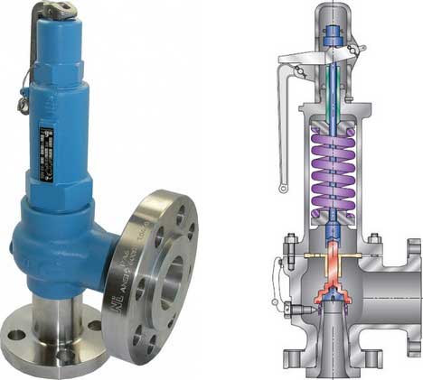
About AG’s 63B Safety ValveType 63B valves are direct spring-operated safety valves suitable for medium set pressure gas, vapor and liquid or gas thermal relief applications. Specific valve types are available for gas, vapor, liquid; gas or liquid thermal relief, steam, cryogenic and chemically active applications.
The 63B’s brass construction offers an economical valve for carbon dioxide, natural gas and general gas or vapor services. Yet, these relief valves use special internals and soft seals to provide optimum accurate performance.
About Seal Tightness Performance SpecsAll pressure relief valves are checked for seal leakage per procedures outlined in API 527. The following operating pressures will allow for bubble-tight seat sealing performance.

RM2BHFJN7–Coryton, Stanford-le-Hope, Essex, UK. 25th Apr, 2020. A build up of pressure caused a safety valve to release at a power station (initially thought to be the oil refinery nearby) in Coryton, close to DP World port cranes on the Thames Estuary, creating steam and noise in the area leading people to believe that there had been an explosion. Local fire brigade and emergency services attended
RMT94YD7–Papin holding a diagram of a steam engine, lithograph, 1689. Denis Papin (August 22, 1647 - 1712) was a French physicist, mathematician and inventor. He worked with Robert Boyle from 1676-79, publishing an account of his work in Continuation of New Experiments (1680). During this period, Papin invented the steam digester, a type of pressure cooker with a safety valve.
RMGE4JB3–(September 6, 1963) Vent flowing cryogenic fuel and T/C Rake mounted on a 1/10 scale model Centaur in the l0 x l0 Foot Supersonic Wind Tunnel. The fuel being used is liquid hydrogen. The point of the test is to determine how far to expel venting fuel from the rocket body to prevent explosion at the base of the vehicle. This vent is used as a safety valve for the fumes created when loading the fuel tanks during launch preparation. Liquid hydrogen has to be kept at a very low temperature. As it heats, it turns to gas and increases pressure in the tank. It therefore has to be vented overboard whi
RMMR3WYE–Illustration depicting Papin"s steam engine (1707) for pumping water from mines. It was the first engine to use the safety valve he had invented twenty-seven years earlier for his "digester". (1647-1713) a French physicist, mathematician and inventor, best known for his pioneering invention of the steam digester, the forerunner of the pressure cooker and of the steam engine. Dated 19th century
RM2BHFJR5–Coryton, Stanford-le-Hope, Essex, UK. 25th Apr, 2020. A build up of pressure caused a safety valve to release at a power station (initially thought to be the oil refinery nearby) in Coryton, close to DP World port cranes on the Thames Estuary, creating steam and noise in the area leading people to believe that there had been an explosion. Local fire brigade and emergency services attended
RME14RJF–Apr. 18, 2012 - The main road through the area is always busy: The gaunt, Barren Hills are a constant reminder of the wilderness of the territory afar. The safety valve with its ever-burning flame at the top is behind the wire pending on the night.
RMCYXCAB–A well engineered brass and ferrous metal model gas fired horizontal stationary steam set, The brass boiler with metal cladding and normal fittings, weight and lever safety valve, main stop and lagged steam line to single horizontal cylinder¦ mill engine with overmounted valve chest and brass bound cylinder, barrelled connecting rod, counterbalanced crankshaft, spoked flywheel and multi rope pulley. Other details include feed water heater and hand feed pump ,the whole finished in maroon, black and polished brightwork and mounted on a brick and tiled plinth with, Additional-Rights-Clearences-NA
RMT965J2–Color enhanced lithograph of Papin holding a diagram of a steam engine, 1689. Denis Papin (August 22, 1647 - 1712) was a French physicist, mathematician and inventor. He worked with Robert Boyle from 1676-79, publishing an account of his work in Continuation of New Experiments (1680). During this period, Papin invented the steam digester, a type of pressure cooker with a safety valve.
RMW56XWK–Model of a Hydraulic Press, Model of a simple hydraulic press on a wooden floorboard. On the one hand is a manually operated pump, equipped with a pump arm, regulator, overflow and safety valve. The pump arm can be set in two positions. The regulator is a screw valve. The safety valve is adjusted with a weight. A tube for the liquid runs from the pump to the bottom of the press, where an oval press platform is pushed upwards., Joseph Bramah (possibly), United Kingdom, 1820, iron (metal), copper (metal), wood (plant material), model: h 41 cm × w 56 cm × d 27 cm packaging capsule: h 45.5 cm × w
RMMR3X05–Illustration depicting Papin"s steam engine (1707) for pumping water from mines. It was the first engine to use the safety valve he had invented twenty-seven years earlier for his "digester". (1647-1713) a French physicist, mathematician and inventor, best known for his pioneering invention of the steam digester, the forerunner of the pressure cooker and of the steam engine. Dated 19th century
RM2JM8GB6–Alain Sauthier, Director of Nant de Drance poses in front of a safety valve of the penstock in the newly operational Nant de Drance pumped storage electricity power plant in Finhaut, Switzerland, August 4, 2022. REUTERS/Denis Balibouse
RMCYXC6B–A well engineered brass and ferrous metal model gas fired horizontal stationary steam set, The brass boiler with metal cladding and normal fittings, weight and lever safety valve, main stop and lagged steam line to single horizontal cylinder¦ mill engine with overmounted valve chest and brass bound cylinder, barrelled connecting rod, counterbalanced crankshaft, spoked flywheel and multi rope pulley. Other details include feed water heater and hand feed pump ,the whole finished in maroon, black and polished brightwork and mounted on a brick and tiled plinth with, Additional-Rights-Clearences-NA
RF2JHG6MN–An industrial pressure safety valve, abbreviated as "psv" a well-known concept in the industry. Specially made to prevent dangerous high pressures in
RMP3880C–. Grand Geyser Cone and safety valve, Yellowstone National Park. Coverage: 1881-1889. Source Imprint: Fargo, D.T. : F. Jay Haynes, 1881-1889.. Digital item published 1-25-2006; updated 2-12-2009. 129 Grand Geyser Cone and safety valve, Yellowstone National Park, by Haynes, F. Jay (Frank Jay), 1853-1921
RM2JM8G81–Alain Sauthier, Director of Nant de Drance talks to a journalist in front of a safety valve of the penstock in the newly operational Nant de Drance pumped storage electricity power plant in Finhaut, Switzerland, August 4, 2022. REUTERS/Denis Balibouse
RF2JHG6N4–An industrial pressure safety valve, abbreviated as "psv" a well-known concept in the industry. Specially made to prevent dangerous high pressures in
RMP38806–. Grand Geyser Cone and safety valve, Yellowstone National Park. Coverage: 1881-1889. Source Imprint: Fargo, D.T. : F. Jay Haynes, 1881-1889.. Digital item published 1-25-2006; updated 2-12-2009. 129 Grand Geyser Cone and safety valve, Yellowstone National Park, by Haynes, F. Jay (Frank Jay), 1853-1921 2
RM2D3PPTK–Iraqi looters wave to the passing convoy of U.S. Marines as they ride a stolen small construction vehicle in the suburbs of Iraqi capital Baghdad April 7, 2003. British Air Marshal Brian Burridge said during his briefing at Central Command on Monday looting was almost "an inevitability". "There is a release of pent up annoyance and hatred against the Ba"ath Party and the Ba"ath regime but once that safety valve is blown...the business of protecting property becomes easier," he said. REUTERS/Oleg Popov OP/AA
RMTWH30F–Relief and safety valve of turbine unit no. 1, located in the subway below the Generator Room; looking south. The safety valve was manufactured by the Chapman Valve Company of Springfield, Massachusetts. It is identical to the adjacent safety valve for turbine unit no. 2. Photo by Jet Lowe, HAER, 1989. - Puget Sound Power and Light Company, White River Hydroelectric Project, 600 North River Avenue, Dieringer, Pierce County, WA; Shuffletin, Samuel L; Stine, Charles; Webster, Edwin; Baker, Charles H
RMD6K57N–A technician walks away from the safety valve of the drill on the drilling platform of German-Canadian oil company Firma CEP (Central European Petroleum GmbH) near Pudagla on the island of Usedom, Germany, 02 April 2012. After suspedning the controversial search for oil on Usedom in the fall of 2011, work on the the platform now starts up again. Photo: STEFAN SAUER
RM2CF74YH–Vent flowing cryogenic fuel and T/C Rake mounted on a 1/10 scale model Centaur in the l0 x l0 Foot Supersonic Wind Tunnel. The fuel being used is liquid hydrogen. The point of the test is to determine how far to expel venting fuel from the rocket body to prevent explosion at the base of the vehicle. This vent is used as a safety valve for the fumes created when loading the fuel tanks during launch preparation. Liquid hydrogen has to be kept at a very low temperature. As it heats, it turns to gas and increases pressure in the tank. It therefore has to be vented overboard while the rocket sits o
Safety valves are used in a variety of applications, including air/gas, vapor, steam and liquid service. Flotech has been approved by the National Board of Boiler and Pressure Vessel Inspectors to perform safety and relief valve testing, repair and certification.
Our valve experts will focus on getting your valves tested, repaired and quickly set to the exact specifications. We evaluate the repair condition of every valve and will recommend the right solution to manage your maintenance program.

(a) Qualifications of individual who adjusts. Safety relief valves shall be set and adjusted by a competent person who is thoroughly familiar with the construction and operation of the valve being set.
(b) Opening pressures. At least one safety relief valve shall be set to open at a pressure not exceeding the MAWP. Safety relief valves shall be set to open at pressures not exceeding 6 psi above the MAWP.
(c) Setting procedures. When setting safety relief valves, two steam gauges shall be used, one of which must be so located that it will be in full view of the persons engaged in setting such valves; and if the pressure indicated by the gauges varies more than 3 psi they shall be removed from the boiler, tested, and corrected before the safety relief valves are set. Gauges shall in all cases be tested immediately before the safety relief valves are set or any change made in the setting. When setting safety relief valves, the water level shall not be higher than
(d) Labeling of lowest set pressure. The set pressure of the lowest safety relief valve shall be indicated on a tag or label attached to the steam gauge so that it may be clearly read while observing the steam gauge.

This website is using a security service to protect itself from online attacks. The action you just performed triggered the security solution. There are several actions that could trigger this block including submitting a certain word or phrase, a SQL command or malformed data.
Years ago, it was not uncommon to read news about tragic boiler explosions, sometimes resulting in mass destruction. Today, boilers are equipped with important safety devises to help protect against these types of catastrophes. Let’s take a look at the most critical of these devices: the safety valve.
The safety valve is one of the most important safety devices in a steam system. Safety valves provide a measure of security for plant operators and equipment from over pressure conditions. The main function of a safety valve is to relieve pressure. It is located on the boiler steam drum, and will automatically open when the pressure of the inlet side of the valve increases past the preset pressure. All boilers are required by ASME code to have at least one safety valve, dependent upon the maximum flow capacity (MFC) of the boiler. The total capacity of the safety valve at the set point must exceed the steam control valve’s MFC if the steam valve were to fail to open. In most cases, two safety valves per boiler are required, and a third may be needed if they do not exceed the MFC.
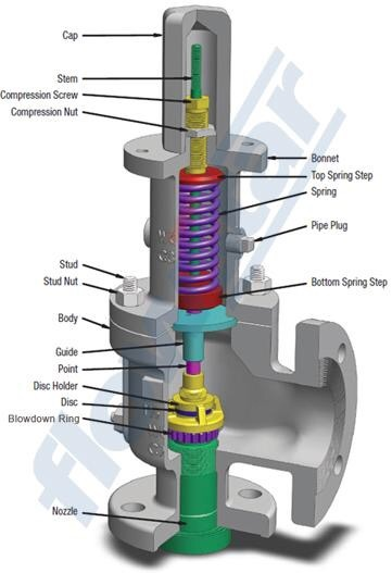
There are three main parts to the safety valve: nozzle, disc, and spring. Pressurized steam enters the valve through the nozzle and is then threaded to the boiler. The disc is the lid to the nozzle, which opens or closes depending on the pressure coming from the boiler. The spring is the pressure controller.
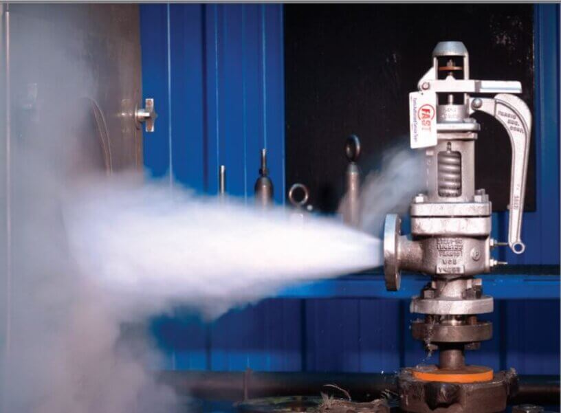
As a boiler starts to over pressure, the nozzle will start to receive a higher pressure coming from the inlet side of the valve, and will start to sound like it is simmering. When the pressure becomes higher than the predetermined pressure of the spring, the disc will start to lift and release the steam, creating a “pop” sound. After it has released and the steam and pressure drops below the set pressure of the valve, the spring will close the disc. Once the safety valve has popped, it is important to check the valve to make sure it is not damaged and is working properly.
A safety valve is usually referred to as the last line of safety defense. Without safety valves, the boiler can exceed it’s maximum allowable working pressure (MAWP) and not only damage equipment, but also injure or kill plant operators that are close by. Many variables can cause a safety valve on a boiler to lift, such as a compressed air or electrical power failure to control instrumentation, or an imbalance of feedwater rate caused by an inadvertently shut or open isolation valve.
Once a safety valve has lifted, it is important to do a complete boiler inspection and confirm that there are no other boiler servicing issues. A safety valve should only do its job once; safety valves should not lift continuously. Lastly, it is important to have the safety valves fully repaired, cleaned and recertified with a National Board valve repair (VR) stamp as required by local code or jurisdiction. Safety valves are a critical component in a steam system, and must be maintained.
All of Nationwide Boiler’s rental boilers include on to two safety valves depending on the size; one set at design pressure and the other set slightly higher than design. By request, we can reset the safeties to a lower pressure if the application requires it. In addition, the valves are thoroughly checked after every rental and before going out to a new customer, and they are replaced and re-certified as needed.


 8613371530291