
how to set safety valve pressure free sample

In order to ensure that the maximum allowable accumulation pressure of any system or apparatus protected by a safety valve is never exceeded, careful consideration of the safety valve’s position in the system has to be made. As there is such a wide range of applications, there is no absolute rule as to where the valve should be positioned and therefore, every application needs to be treated separately.
A common steam application for a safety valve is to protect process equipment supplied from a pressure reducing station. Two possible arrangements are shown in Figure 9.3.3.
The safety valve can be fitted within the pressure reducing station itself, that is, before the downstream stop valve, as in Figure 9.3.3 (a), or further downstream, nearer the apparatus as in Figure 9.3.3 (b). Fitting the safety valve before the downstream stop valve has the following advantages:
• The safety valve can be tested in-line by shutting down the downstream stop valve without the chance of downstream apparatus being over pressurised, should the safety valve fail under test.
• When setting the PRV under no-load conditions, the operation of the safety valve can be observed, as this condition is most likely to cause ‘simmer’. If this should occur, the PRV pressure can be adjusted to below the safety valve reseat pressure.
Indeed, a separate safety valve may have to be fitted on the inlet to each downstream piece of apparatus, when the PRV supplies several such pieces of apparatus.
• If supplying one piece of apparatus, which has a MAWP pressure less than the PRV supply pressure, the apparatus must be fitted with a safety valve, preferably close-coupled to its steam inlet connection.
• If a PRV is supplying more than one apparatus and the MAWP of any item is less than the PRV supply pressure, either the PRV station must be fitted with a safety valve set at the lowest possible MAWP of the connected apparatus, or each item of affected apparatus must be fitted with a safety valve.
• The safety valve must be located so that the pressure cannot accumulate in the apparatus viaanother route, for example, from a separate steam line or a bypass line.
It could be argued that every installation deserves special consideration when it comes to safety, but the following applications and situations are a little unusual and worth considering:
• Fire - Any pressure vessel should be protected from overpressure in the event of fire. Although a safety valve mounted for operational protection may also offer protection under fire conditions,such cases require special consideration, which is beyond the scope of this text.
• Exothermic applications - These must be fitted with a safety valve close-coupled to the apparatus steam inlet or the body direct. No alternative applies.
• Safety valves used as warning devices - Sometimes, safety valves are fitted to systems as warning devices. They are not required to relieve fault loads but to warn of pressures increasing above normal working pressures for operational reasons only. In these instances, safety valves are set at the warning pressure and only need to be of minimum size. If there is any danger of systems fitted with such a safety valve exceeding their maximum allowable working pressure, they must be protected by additional safety valves in the usual way.
In order to illustrate the importance of the positioning of a safety valve, consider an automatic pump trap (see Block 14) used to remove condensate from a heating vessel. The automatic pump trap (APT), incorporates a mechanical type pump, which uses the motive force of steam to pump the condensate through the return system. The position of the safety valve will depend on the MAWP of the APT and its required motive inlet pressure.
This arrangement is suitable if the pump-trap motive pressure is less than 1.6 bar g (safety valve set pressure of 2 bar g less 0.3 bar blowdown and a 0.1 bar shut-off margin). Since the MAWP of both the APT and the vessel are greater than the safety valve set pressure, a single safety valve would provide suitable protection for the system.
However, if the pump-trap motive pressure had to be greater than 1.6 bar g, the APT supply would have to be taken from the high pressure side of the PRV, and reduced to a more appropriate pressure, but still less than the 4.5 bar g MAWP of the APT. The arrangement shown in Figure 9.3.5 would be suitable in this situation.
Here, two separate PRV stations are used each with its own safety valve. If the APT internals failed and steam at 4 bar g passed through the APT and into the vessel, safety valve ‘A’ would relieve this pressure and protect the vessel. Safety valve ‘B’ would not lift as the pressure in the APT is still acceptable and below its set pressure.
It should be noted that safety valve ‘A’ is positioned on the downstream side of the temperature control valve; this is done for both safety and operational reasons:
Operation - There is less chance of safety valve ‘A’ simmering during operation in this position,as the pressure is typically lower after the control valve than before it.
Also, note that if the MAWP of the pump-trap were greater than the pressure upstream of PRV ‘A’, it would be permissible to omit safety valve ‘B’ from the system, but safety valve ‘A’ must be sized to take into account the total fault flow through PRV ‘B’ as well as through PRV ‘A’.
A pharmaceutical factory has twelve jacketed pans on the same production floor, all rated with the same MAWP. Where would the safety valve be positioned?
One solution would be to install a safety valve on the inlet to each pan (Figure 9.3.6). In this instance, each safety valve would have to be sized to pass the entire load, in case the PRV failed open whilst the other eleven pans were shut down.
If additional apparatus with a lower MAWP than the pans (for example, a shell and tube heat exchanger) were to be included in the system, it would be necessary to fit an additional safety valve. This safety valve would be set to an appropriate lower set pressure and sized to pass the fault flow through the temperature control valve (see Figure 9.3.8).

Safety is of the utmost importance when dealing with pressure relief valves. The valve is designed to limit system pressure, and it is critical that they remain in working order to prevent an explosion. Explosions have caused far too much damage in companies over the years, and though pressurized tanks and vessels are equipped with pressure relief vales to enhance safety, they can fail and result in disaster.
That’s also why knowing the correct way to test the valves is important. Ongoing maintenance and periodic testing of pressurized tanks and vessels and their pressure relief valves keeps them in working order and keep employees and their work environments safe. Pressure relief valves must be in good condition in order to automatically lower tank and vessel pressure; working valves open slowly when the pressure gets high enough to exceed the pressure threshold and then closes slowly until the unit reaches the low, safe threshold. To ensure the pressure relief valve is in good working condition, employees must follow best practices for testing them including:
If you consider testing pressure relief valves a maintenance task, you’ll be more likely to carry out regular testing and ensure the safety of your organization and the longevity of your
It’s important to note, however, that the American Society of Mechanical Engineers (ASME) and National Board Inspection Code (NBIC), as well as state and local jurisdictions, may set requirements for testing frequency. Companies are responsible for checking with these organizations to become familiar with the testing requirements. Consider the following NBIC recommendations on the frequency for testing relief valves:
High-pressure steam boilers greater than 15 psi and less than 400 psi – perform manual check every six months and pressure test annually to verify nameplate set pressure
High-pressure steam boilers 400 psi and greater – pressure test to verify nameplate set pressure every three years or as determined by operating experience as verified by testing history
High-temperature hot water boilers (greater than 160 psi and/or 250 degrees Fahrenheit) – pressure test annually to verify nameplate set pressure. For safety reasons, removal and testing on a test bench is recommended
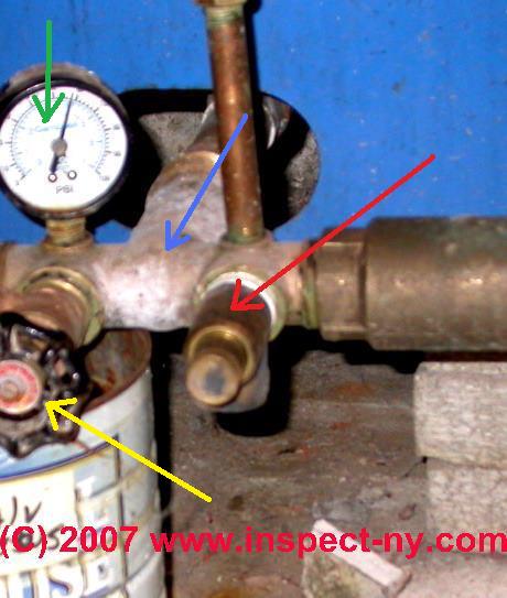
When testing the pressure relief valve, raise and lower the test lever several times. The lever will come away from the brass stem and allow hot water to come out of the end of the drainpipe. The water should flow through the pipe, and then you should turn down the pressure to stop the leak, replace the lever, and then increase the pressure.
One of the most common problems you can address with regular testing is the buildup of mineral salt, rust, and corrosion. When buildup occurs, the valve will become non-operational; the result can be an explosion. Regular testing helps you discover these issues sooner so you can combat them and keep your boiler and valve functioning properly. If no water flows through the pipe, or if there is a trickle instead of a rush of water, look for debris that is preventing the valve from seating properly. You may be able to operate the test lever a few times to correct the issue. You will need to replace the valve if this test fails.
When testing relief valves, keep in mind that they have two basic functions. First, they will pop off when the pressure exceeds its safety threshold. The valve will pop off and open to exhaust the excess pressure until the tank’s pressure decreases to reach the set minimum pressure. After this blowdown process occurs, the valve should reset and automatically close. One important testing safety measure is to use a pressure indicator with a full-scale range higher than the pop-off pressure.
Thus, you need to be aware of the pop-off pressure point of whatever tank or vessel you test. You always should remain within the pressure limits of the test stand and ensure the test stand is assembled properly and proof pressure tested. Then, take steps to ensure the escaping pressure from the valve is directed away from the operator and that everyone involved in the test uses safety shields and wears safety eye protection.
After discharge – Because pressure relief valves are designed to open automatically to relieve pressure in your system and then close, they may be able to open and close multiple times during normal operation and testing. However, when a valve opens, debris may get into the valve seat and prevent the valve from closing properly. After discharge, check the valve for leakage. If the leakage exceeds the original settings, you need to repair the valve.
According to local jurisdictional requirements – Regulations are in place for various locations and industries that stipulate how long valves may operate before needing to be repair or replaced. State inspectors may require valves to be disassembled, inspected, repaired, and tested every five years, for instance. If you have smaller valves and applications, you can test the valve by lifting the test lever. However, you should do this approximately once a year. It’s important to note that ASME UG136A Section 3 requires valves to have a minimum of 75% operating pressure versus the set pressure of the valve for hand lifting to be performed for these types of tests.
Depending on their service and application– The service and application of a valve affect its lifespan. Valves used for clean service like steam typically last at least 20 years if they are not operated too close to the set point and are part of a preventive maintenance program. Conversely, valves used for services such as acid service, those that are operated too close to the set point, and those exposed to dirt or debris need to be replaced more often.
Pressure relief valves serve a critical role in protecting organizations and employees from explosions. Knowing how and when to test and repair or replace them is essential.

A little product education can make you look super smart to customers, which usually means more orders for everything you sell. Here’s a few things to keep in mind about safety valves, so your customers will think you’re a genius.
A safety valve is required on anything that has pressure on it. It can be a boiler (high- or low-pressure), a compressor, heat exchanger, economizer, any pressure vessel, deaerator tank, sterilizer, after a reducing valve, etc.
There are four main types of safety valves: conventional, bellows, pilot-operated, and temperature and pressure. For this column, we will deal with conventional valves.
A safety valve is a simple but delicate device. It’s just two pieces of metal squeezed together by a spring. It is passive because it just sits there waiting for system pressure to rise. If everything else in the system works correctly, then the safety valve will never go off.
A safety valve is NOT 100% tight up to the set pressure. This is VERY important. A safety valve functions a little like a tea kettle. As the temperature rises in the kettle, it starts to hiss and spit when the water is almost at a boil. A safety valve functions the same way but with pressure not temperature. The set pressure must be at least 10% above the operating pressure or 5 psig, whichever is greater. So, if a system is operating at 25 psig, then the minimum set pressure of the safety valve would be 30 psig.
Most valve manufacturers prefer a 10 psig differential just so the customer has fewer problems. If a valve is positioned after a reducing valve, find out the max pressure that the equipment downstream can handle. If it can handle 40 psig, then set the valve at 40. If the customer is operating at 100 psig, then 110 would be the minimum. If the max pressure in this case is 150, then set it at 150. The equipment is still protected and they won’t have as many problems with the safety valve.
Here’s another reason the safety valve is set higher than the operating pressure: When it relieves, it needs room to shut off. This is called BLOWDOWN. In a steam and air valve there is at least one if not two adjusting rings to help control blowdown. They are adjusted to shut the valve off when the pressure subsides to 6% below the set pressure. There are variations to 6% but for our purposes it is good enough. So, if you operate a boiler at 100 psig and you set the safety valve at 105, it will probably leak. But if it didn’t, the blowdown would be set at 99, and the valve would never shut off because the operating pressure would be greater than the blowdown.
All safety valves that are on steam or air are required by code to have a test lever. It can be a plain open lever or a completely enclosed packed lever.
Safety valves are sized by flow rate not by pipe size. If a customer wants a 12″ safety valve, ask them the flow rate and the pressure setting. It will probably turn out that they need an 8×10 instead of a 12×16. Safety valves are not like gate valves. If you have a 12″ line, you put in a 12″ gate valve. If safety valves are sized too large, they will not function correctly. They will chatter and beat themselves to death.
Safety valves need to be selected for the worst possible scenario. If you are sizing a pressure reducing station that has 150 psig steam being reduced to 10 psig, you need a safety valve that is rated for 150 psig even though it is set at 15. You can’t put a 15 psig low-pressure boiler valve after the reducing valve because the body of the valve must to be able to handle the 150 psig of steam in case the reducing valve fails.
The seating surface in a safety valve is surprisingly small. In a 3×4 valve, the seating surface is 1/8″ wide and 5″ around. All it takes is one pop with a piece of debris going through and it can leak. Here’s an example: Folgers had a plant in downtown Kansas City that had a 6×8 DISCONTINUED Consolidated 1411Q set at 15 psig. The valve was probably 70 years old. We repaired it, but it leaked when plant maintenance put it back on. It was after a reducing valve, and I asked him if he played with the reducing valve and brought the pressure up to pop the safety valve. He said no, but I didn’t believe him. I told him the valve didn’t leak when it left our shop and to send it back.
When it came back, I laid it down on the outlet flange and looked up the inlet. There was a 12″ welding rod with the tip stuck between the seat and the disc. That rod was from the original construction and didn’t get blown out properly and just now it got set free. The maintenance guy didn’t believe me and came over and saw it for himself (this was before cell phones when you could take a picture).
If there is a problem with a safety valve, 99% of the time it is not the safety valve or the company that set it. There may be other reasons that the pressure is rising in the system before the safety valve. Some ethanol plants have a problem on starting up their boilers. The valves are set at 150 and they operate at 120 but at startup the pressure gets away from them and there is a spike, which creates enough pressure to cause a leak until things get under control.
If your customer is complaining that the valve is leaking, ask questions before a replacement is sent out. What is the operating pressure below the safety valve? If it is too close to the set pressure then they have to lower their operating pressure or raise the set pressure on the safety valve.
Is the valve installed in a vertical position? If it is on a 45-degree angle, horizontal, or upside down then it needs to be corrected. I have heard of two valves that were upside down in my 47 years. One was on a steam tractor and the other one was on a high-pressure compressor station in the New Mexico desert. He bought a 1/4″ valve set at 5,000 psig. On the outlet side, he left the end cap in the outlet and put a pin hole in it so he could hear if it was leaking or not. He hit the switch and when it got up to 3,500 psig the end cap came flying out like a missile past his nose. I told him to turn that sucker in the right direction and he shouldn’t have any problems. I never heard from him so I guess it worked.
If the set pressure is correct, and the valve is vertical, ask if the outlet piping is supported by something other than the safety valve. If they don’t have pipe hangers or a wall or something to keep the stress off the safety valve, it will leak.
There was a plant in Springfield, Mo. that couldn’t start up because a 2″ valve was leaking on a tank. It was set at 750 psig, and the factory replaced it 5 times. We are not going to replace any valves until certain questions are answered. I was called to solve the problem. The operating pressure was 450 so that wasn’t the problem. It was in a vertical position so we moved on to the piping. You could tell the guy was on his cell phone when I asked if there was any piping on the outlet. He said while looking at the installation that he had a 2″ line coming out into a 2×3 connection going up a story into a 3×4 connection and going up another story. I asked him if there was any support for this mess, and he hung up the phone. He didn’t say thank you, goodbye, or send me a Christmas present.
Pipe dope is another problem child. Make sure your contractors ease off on the pipe dope. That is enough for today, class. Thank you for your patience. And thank you for your business.
Safety valves and pressure relief valves are crucial for one main reason: safety. This means safety for the plant and equipment as well as safety for plant personnel and the surrounding environment.
Safety valves and pressure relief valves protect vessels, piping systems, and equipment from overpressure, which, if unchecked, can not only damage a system but potentially cause an explosion. Because these valves play such an important role, it’s absolutely essential that the right valve is used every time.
The valve size must correspond to the size of the inlet and discharge piping. The National Board specifies that the both the inlet piping and the discharge piping connected to the valve must be at least as large as the inlet/discharge opening on the valve itself.
The connection types are also important. For example, is the connection male or female? Flanged? All of these factors help determine which valve to use.
The set pressure of the valve must not exceed the maximum allowable working pressure (MAWP) of the boiler or other vessel. What this means is that the valve must open at or below the MAWP of the equipment. In turn, the MAWP of the equipment should be at least 10% greater than the highest expected operating pressure under normal circumstances.
Temperature affects the volume and viscosity of the gas or liquid flowing through the system. Temperature also helps determine the ideal material of construction for the valve. For example, steel valves can handle higher operating temperatures than valves made of either bronze or iron. Both the operating and the relieving temperature must be taken into account.
Back pressure, which may be constant or variable, is pressure on the outlet side of the pressure relief valve as a result of the pressure in the discharge system. It can affect the set pressure of the upstream valve and cause it to pop open repeatedly, which can damage the valve.
For installations with variable back pressure, valves should be selected so that the back pressure doesn’t exceed 10% of the valve set pressure. For installations with high levels of constant back pressure, a bellows-sealed valve or pilot-operated valve may be required.
Different types of service (steam, air, gas, etc.) require different valves. In addition, the valve material of construction needs to be appropriate for the service. For example, valves made of stainless steel are preferable for corrosive media.
Safety valves and relief valves must be able to relieve pressure at a certain capacity. The required capacity is determined by several factors including the geometry of the valve, the temperature of the media, and the relief discharge area.
These are just the basic factors that must be considered when selecting and sizing safety valves and relief valves. You must also consider the physical dimensions of the equipment and the plant, as well as other factors related to the environment in which the valve will operate.

This website is using a security service to protect itself from online attacks. The action you just performed triggered the security solution. There are several actions that could trigger this block including submitting a certain word or phrase, a SQL command or malformed data.

— Pressure safety relief valves are typically used to control pressure on boilers in heating systems, on stored hot water cylinders in domestic hot water systems, and generally in water systems. T&P relief Valve Function:
This is caused by water expanding during the heating cycle. The T/P valve will then relieve pressure by releasing hot water drips to the drain line. It is recommended that an expansion control valve be fitted to the cold water supply line to reduce cold water(not hot water) during the heating cycle expansion, thereby saving energy and increasing the life of the T&P relief valve. Local regulations may require installing an expansion control valve in the cold water supply line.
With so many brass pressure relief valves to choose from, it can be challenging to find the right one. Whether you are looking for a valve that has a higher flow rate or is more durable, here are some essential things to consider when choosing your next brass pressure relief valve:
Once you have answered these questions, you can narrow your search for the perfect brass pressure relief valve. For example, if you have a system that operates at a high PSI, you will need a valve to withstand higher pressures. Conversely, if you have a minor piping system, you may consider a valve with a lower flow rate.
Always read the manufacturer’s instructions carefully before installing, no matter what type of valve you choose. By following these simple guidelines, you can be confident that your new brass pressure relief valve will provide years of reliable service.
Answering these questions will make it easier to narrow your search for the perfect brass pressure relief valve. For example: if you have a more extensive piping system with high operating pressures, you may want to consider one that can handle higher flow rates and has extra features (such as a pilot light). Conversely, if you choose between two valves that can withstand up to 150 PSI but only differ by 0.25 GPM in their flow rate, then maybe select based on price alone. The key here is knowing what factors matter most when purchasing something like this, so don’t be afraid to ask for help from a qualified technician.
Like anything else, it’s essential to read the manufacturer’s instructions carefully before installation. Following these guidelines ensures that your new brass pressure relief valve will provide years of quality service!
Once you have chosen the perfect brass pressure relief valve for your system, it is essential to install it properly. These instructions are based on a typical installation with similar-sized piping and valves. The first step in choosing an appropriate location for installing your new valve will be finding out what type of piping system you currently have.
Depending on the answer, there may or may not be any further steps required before moving on to the next section: Determining pipe size. If this was already calculated during Step One (piping systems), then proceed directly here; if not, please continue reading below:
Most sizing charts that can help determine pipe sizes generally refer back to either inch-pound units or PSI; depending on where you live, one of these measurements will be more common. To convert your pipe size into PSI, you can use this online calculator or do it by hand:
Once you have determined the pipe size in PSI, it is time to find what pressure relief valve will work with your system. Now that you know the piping system and pipe size, finding a brass pressure relief valve should be as easy as pie!

In 2023, the sales of Pressure Relief Valve in Global Market is expected to reach US$ 4,509.8 Mn. and is projected to expand steadily at a CAGR of 4.6% to reach a market valuation of close to US$ 7,070.9 Mn by 2033.
In recent past valve costs have increased globally, which can be attributed to growing tariffs from the North American region, particularly the US. Leading players from the European and American regions have facilities in both high- and low-income nations. In contrast, labor-intensive production processes like the creation of rough castings for valves and valve components take occur in low-cost manufacturing nations like China. These processes include design, research and development, and testing. Due to low prices and quality maintenance, OEMs are able to do so. However, growing US government tariffs on steel and aluminum imports from China have had a substantial negative influence on pressure relief valve profit margins and costs.
However, the rapid growing industrialization and increasing safety precaution are the factors that are expected to fuel the market growth of Pressure relief valves across the globe during the assessment period, the Pressure relief valve market is expected to experience demand growth with CAGR of 4.6% during the forecasted period.
From 2017 to 2022, the Global Pressure Relief Valve Market expanded at a CAGR of around 2.4%. The advancement in product technology to connect the valves digitally enables end users to monitor pressure in various applications digitally which has generated significant demand from the various industry sector during the forecasted period.
Numerous applications where pressure levels are crucial for continuous and efficient machinery performance demand for the utilization of pressure relief valves. These include the various sectors operating with steam, air, gas, or liquid such as oil and gas, power generation and the petrochemicals industry. Multiphase applications and chemical processing systems both have high installation rate of pressure relief valves. With rapid development industrial sector & expansion of oil & Gas pipelines across the developing as well as developed economies the demand for PRV is also expected to expand, Persistence Market Research expects the market to expand at a 4.6% CAGR through 2033.
Both emerging and advanced regions have seen a surge in oil and gas consumption. In order to meet the rising demand and supply for oil and gas, industries are concentrating on expanding their production facilities through onshore and offshore exploration. Since the oil and gas sector is one of the key end uses for the global pressure relief valves market thus expanding oil & gas Sector is generating lucrative opportunity for the demand growth of PRVs in upcoming period.
Furthermore, growing regulation for use of pressure relief valves in power generation sector is further set to create opportunities for the market. For instance, there are currently about 50 nuclear reactors under development. By safeguarding turbines, super heaters, and boilers to enable the stations to operate at prescribed pressures, pressure relief valves play a crucial part in the successful and safe operations of nuclear facilities.
Manufacturing businesses will be significantly and directly impacted by the Asia Pacific region"s volatile and uncertain markets. The operational costs of the manufacturing processes, which are the main concern of manufacturers, will be directly impacted by rising tariffs and raw material costs used to manufacture valves. Rising raw material costs immediately impact the integrity of the supply chain and the selling price of a product. Manufacturers in the Asia Pacific region are becoming increasingly concerned about the steady growth in cost of the raw materials used to make pressure relief valves. This is expected to, restrain the market"s expansion for pressure relief valves.
With an absolute dollar opportunity of around US$ 600.0 Mn, North America is expected to be the most lucrative market for pressure relief valves suppliers. U.S is leading the North American market, and is expected to witness a 1.5X growth during 2023-2033. The market for pressure relief valves has recently experienced considerable growth in sales as a result of growing industrialisation and advancements in urban waste water management systems. Apart from that U.S. is also second largest importer & Exporter of Pressure relief valves, which makes it a targeting region for the manufacturers & Suppliers.
In 2023, the German Pressure Relief Valve market is likely to hold around 25% of the market by value share in Europe. Germany"s extensive remanufacturing capabilities are likely to play a crucial part in development of industrial growth. Sales growth for pressure relief valves is anticipated to be boosted in the upcoming years as manufacturers are planning to invest more in safety & developments of industrial Sites.
With a CAGR of 5.9%, India is expected to lead the South Asian market throughout the assessment period and experience significant expansion. Pressure relief valve demand is anticipated to increase as a result of India"s low production and labour costs, as well as less regulations & certifications required for PRVs, which are encouraging various industry players, including oil & gas, pharmaceutical, chemical, and textile manufacturers, to expand their manufacturing facilities in India.
By the end of the assessment period, spring-loaded pressure relief valves will hold a value share of over 40% of the market for pressure relief valves worldwide. Due to its broad range of applications and other technological advantages over other valves, this valve is widely utilized. The design and use of pressure relief valves is covered by a number of international codes and standards, the most popular of which being the ASME (American organization for mechanical engineers) Boiler and Pressure Vessel Code, also known as ASME code. Despite the fact that this code varies by region.
In 2023, the demand for pressure relief valves is primarily driven by the Medium Pressure segment in Set Pressure segment of the market. By the end of the forecast period, it is projected that pressure relief valves with a medium pressure range will still be widely utilized in a variety of end use sectors. The market for medium pressure relief valves is expected to continue expanding due to rising end-use sectors including oil and gas, chemical, and others.
Caution: If the pressure will exceed the above-mentioned set pressure, the safety valve will open. However, if the flow rate from the gas source exceeds the above-mentioned max. flow rate, the valve would not be able to vent the meter quickly enough.

This website is using a security service to protect itself from online attacks. The action you just performed triggered the security solution. There are several actions that could trigger this block including submitting a certain word or phrase, a SQL command or malformed data.

A safety valve is a valve that acts as a fail-safe. An example of safety valve is a pressure relief valve (PRV), which automatically releases a substance from a boiler, pressure vessel, or other system, when the pressure or temperature exceeds preset limits. Pilot-operated relief valves are a specialized type of pressure safety valve. A leak tight, lower cost, single emergency use option would be a rupture disk.
Safety valves were first developed for use on steam boilers during the Industrial Revolution. Early boilers operating without them were prone to explosion unless carefully operated.
Vacuum safety valves (or combined pressure/vacuum safety valves) are used to prevent a tank from collapsing while it is being emptied, or when cold rinse water is used after hot CIP (clean-in-place) or SIP (sterilization-in-place) procedures. When sizing a vacuum safety valve, the calculation method is not defined in any norm, particularly in the hot CIP / cold water scenario, but some manufacturers
The earliest and simplest safety valve was used on a 1679 steam digester and utilized a weight to retain the steam pressure (this design is still commonly used on pressure cookers); however, these were easily tampered with or accidentally released. On the Stockton and Darlington Railway, the safety valve tended to go off when the engine hit a bump in the track. A valve less sensitive to sudden accelerations used a spring to contain the steam pressure, but these (based on a Salter spring balance) could still be screwed down to increase the pressure beyond design limits. This dangerous practice was sometimes used to marginally increase the performance of a steam engine. In 1856, John Ramsbottom invented a tamper-proof spring safety valve that became universal on railways. The Ramsbottom valve consisted of two plug-type valves connected to each other by a spring-laden pivoting arm, with one valve element on either side of the pivot. Any adjustment made to one of valves in an attempt to increase its operating pressure would cause the other valve to be lifted off its seat, regardless of how the adjustment was attempted. The pivot point on the arm was not symmetrically between the valves, so any tightening of the spring would cause one of the valves to lift. Only by removing and disassembling the entire valve assembly could its operating pressure be adjusted, making impromptu "tying down" of the valve by locomotive crews in search of more power impossible. The pivoting arm was commonly extended into a handle shape and fed back into the locomotive cab, allowing crews to "rock" both valves off their seats to confirm they were set and operating correctly.
Safety valves also evolved to protect equipment such as pressure vessels (fired or not) and heat exchangers. The term safety valve should be limited to compressible fluid applications (gas, vapour, or steam).
For liquid-packed vessels, thermal relief valves are generally characterized by the relatively small size of the valve necessary to provide protection from excess pressure caused by thermal expansion. In this case a small valve is adequate because most liquids are nearly incompressible, and so a relatively small amount of fluid discharged through the relief valve will produce a substantial reduction in pressure.
Flow protection is characterized by safety valves that are considerably larger than those mounted for thermal protection. They are generally sized for use in situations where significant quantities of gas or high volumes of liquid must be quickly discharged in order to protect the integrity of the vessel or pipeline. This protection can alternatively be achieved by installing a high integrity pressure protection system (HIPPS).
In the petroleum refining, petrochemical, chemical manufacturing, natural gas processing, power generation, food, drinks, cosmetics and pharmaceuticals industries, the term safety valve is associated with the terms pressure relief valve (PRV), pressure safety valve (PSV) and relief valve.
The generic term is Pressure relief valve (PRV) or pressure safety valve (PSV). PRVs and PSVs are not the same thing, despite what many people think; the difference is that PSVs have a manual lever to open the valve in case of emergency.
Relief valve (RV): an automatic system that is actuated by the static pressure in a liquid-filled vessel. It specifically opens proportionally with increasing pressure
Pilot-operated safety relief valve (POSRV): an automatic system that relieves on remote command from a pilot, to which the static pressure (from equipment to protect) is connected
Low pressure safety valve (LPSV): an automatic system that relieves static pressure on a gas. Used when the difference between the vessel pressure and the ambient atmospheric pressure is small.
Vacuum pressure safety valve (VPSV): an automatic system that relieves static pressure on a gas. Used when the pressure difference between the vessel pressure and the ambient pressure is small, negative and near to atmospheric pressure.
Low and vacuum pressure safety valve (LVPSV): an automatic system that relieves static pressure on a gas. Used when the pressure difference is small, negative or positive and near to atmospheric pressure.
In most countries, industries are legally required to protect pressure vessels and other equipment by using relief valves. Also, in most countries, equipment design codes such as those provided by the ASME, API and other organizations like ISO (ISO 4126) must be complied with. These codes include design standards for relief valves and schedules for periodic inspection and testing after valves have been removed by the company engineer.
Today, the food, drinks, cosmetics, pharmaceuticals and fine chemicals industries call for hygienic safety valves, fully drainable and Cleanable-In-Place. Most are made of stainless steel; the hygienic norms are mainly 3A in the USA and EHEDG in Europe.
The first safety valve was invented by Denis Papin for his steam digester, an early pressure cooker rather than an engine.steelyard" lever a smaller weight was required, also the pressure could easily be regulated by sliding the same weight back and forth along the lever arm. Papin retained the same design for his 1707 steam pump.Greenwich in 1803, one of Trevithick"s high-pressure stationary engines exploded when the boy trained to operate the engine left it to catch eels in the river, without first releasing the safety valve from its working load.
Although the lever safety valve was convenient, it was too sensitive to the motion of a steam locomotive. Early steam locomotives therefore used a simpler arrangement of weights stacked directly upon the valve. This required a smaller valve area, so as to keep the weight manageable, which sometimes proved inadequate to vent the pressure of an unattended boiler, leading to explosions. An even greater hazard was the ease with which such a valve could be tied down, so as to increase the pressure and thus power of the engine, at further risk of explosion.
Although deadweight safety valves had a short lifetime on steam locomotives, they remained in use on stationary boilers for as long as steam power remained.
Weighted valves were sensitive to bouncing from the rough riding of early locomotives. One solution was to use a lightweight spring rather than a weight. This was the invention of Timothy Hackworth on his leaf springs.
These direct-acting spring valves could be adjusted by tightening the nuts retaining the spring. To avoid tampering, they were often shrouded in tall brass casings which also vented the steam away from the locomotive crew.
The Salter coil spring spring balance for weighing, was first made in Britain by around 1770.spring steels to make a powerful but compact spring in one piece. Once again by using the lever mechanism, such a spring balance could be applied to the considerable force of a boiler safety valve.
The spring balance valve also acted as a pressure gauge. This was useful as previous pressure gauges were unwieldy mercury manometers and the Bourdon gauge had yet to be invented.
Paired valves were often adjusted to slightly different pressures too, a small valve as a control measure and the lockable valve made larger and permanently set to a higher pressure, as a safeguard.Sinclair for the Eastern Counties Railway in 1859, had the valve spring with pressure scale behind the dome, facing the cab, and the locked valve ahead of the dome, out of reach of interference.
In 1855, John Ramsbottom, later locomotive superintendent of the LNWR, described a new form of safety valve intended to improve reliability and especially to be tamper-resistant. A pair of plug valves were used, held down by a common spring-loaded lever between them with a single central spring. This lever was characteristically extended rearwards, often reaching into the cab on early locomotives. Rather than discouraging the use of the spring lever by the fireman, Ramsbottom"s valve encouraged this. Rocking the lever freed up the valves alternately and checked that neither was sticking in its seat.
A drawback to the Ramsbottom type was its complexity. Poor maintenance or mis-assembly of the linkage between the spring and the valves could lead to a valve that no longer opened correctly under pressure. The valves could be held against their seats and fail to open or, even worse, to allow the valve to open but insufficiently to vent steam at an adequate rate and so not being an obvious and noticeable fault.Rhymney Railway, even though the boiler was almost new, at only eight months old.
Naylor valves were introduced around 1866. A bellcrank arrangement reduced the strain (percentage extension) of the spring, thus maintaining a more constant force.L&Y & NER.
All of the preceding safety valve designs opened gradually and had a tendency to leak a "feather" of steam as they approached "blowing-off", even though this was below the pressure. When they opened they also did so partially at first and didn"t vent steam quickly until the boiler was well over pressure.
The quick-opening "pop" valve was a solution to this. Their construction was simple: the existing circular plug valve was changed to an inverted "top hat" shape, with an enlarged upper diameter. They fitted into a stepped seat of two matching diameters. When closed, the steam pressure acted only on the crown of the top hat, and was balanced by the spring force. Once the valve opened a little, steam could pass the lower seat and began to act on the larger brim. This greater area overwhelmed the spring force and the valve flew completely open with a "pop". Escaping steam on this larger diameter also held the valve open until pressure had dropped below that at which it originally opened, providing hysteresis.
These valves coincided with a change in firing behaviour. Rather than demonstrating their virility by always showing a feather at the valve, firemen now tried to avoid noisy blowing off, especially around stations or under the large roof of a major station. This was mostly at the behest of stationmasters, but firemen also realised that any blowing off through a pop valve wasted several pounds of boiler pressure; estimated at 20 psi lost and 16 lbs or more of shovelled coal.
Pop valves derived from Adams"s patent design of 1873, with an extended lip. R. L. Ross"s valves were patented in 1902 and 1904. They were more popular in America at first, but widespread from the 1920s on.
Although showy polished brass covers over safety valves had been a feature of steam locomotives since Stephenson"s day, the only railway to maintain this tradition into the era of pop valves was the GWR, with their distinctive tapered brass safety valve bonnets and copper-capped chimneys.
Developments in high-pressure water-tube boilers for marine use placed more demands on safety valves. Valves of greater capacity were required, to vent safely the high steam-generating capacity of these large boilers.Naylor valve) became more critical.distilled feedwater and also a scouring of the valve seats, leading to wear.
High-lift safety valves are direct-loaded spring types, although the spring does not bear directly on the valve, but on a guide-rod valve stem. The valve is beneath the base of the stem, the spring rests on a flange some height above this. The increased space between the valve itself and the spring seat allows the valve to lift higher, further clear of the seat. This gives a steam flow through the valve equivalent to a valve one and a half or twice as large (depending on detail design).
The Cockburn Improved High Lift design has similar features to the Ross pop type. The exhaust steam is partially trapped on its way out and acts on the base of the spring seat, increasing the lift force on the valve and holding the valve further open.
To optimise the flow through a given diameter of valve, the full-bore design is used. This has a servo action, where steam through a narrow control passage is allowed through if it passes a small control valve. This steam is then not exhausted, but is passed to a piston that is used to open the main valve.
There are safety valves known as PSV"s and can be connected to pressure gauges (usually with a 1/2" BSP fitting). These allow a resistance of pressure to be applied to limit the pressure forced on the gauge tube, resulting in prevention of over pressurisation. the matter that has been injected into the gauge, if over pressurised, will be diverted through a pipe in the safety valve, and shall be driven away from the gauge.
There is a wide range of safety valves having many different applications and performance criteria in different areas. In addition, national standards are set for many kinds of safety valves.
Safety valves are required on water heaters, where they prevent disaster in certain configurations in the event that a thermostat should fail. Such a valve is sometimes referred to as a "T&P valve" (Temperature and Pressure valve). There are still occasional, spectacular failures of older water heaters that lack this equipment. Houses can be leveled by the force of the blast.
Pressure cookers are cooking pots with a pressure-proof lid. Cooking at pressure allows the temperature to rise above the normal boiling point of water (100 degrees Celsius at sea level), which speeds up the cooking and makes it more thorough.
Pressure cookers usually have two safety valves to prevent explosions. On older designs, one is a nozzle upon which a weight sits. The other is a sealed rubber grommet which is ejected in a controlled explosion if the first valve gets blocked. On newer generation pressure cookers, if the steam vent gets blocked, a safety spring will eject excess pressure and if that fails, the gasket will expand and release excess pressure downwards between the lid and the pan. Also, newer generation pressure cookers have a safety interlock which locks the lid when internal pressure exceeds atmospheric pressure, to prevent accidents from a sudden release of very hot steam, food and liquid, which would happen if the lid were to be removed when the pan is still slightly pressurised inside (however, the lid will be very hard or impossible to open when the pot is still pressurised).
These figures are based on two measurements, a drop from 225 psi to 205 psi for an LNER Class V2 in 1952 and a smaller drop of 10 psi estimated in 1953 as 16 lbs of coal.
"Trial of HMS Rattler and Alecto". April 1845. The very lowest pressure exhibited "when the screw was out of the water" (as the opponents of the principle term it) was 34 lb, ranging up to 60 lb., on Salter"s balance.


 8613371530291