
hydraulic cylinder safety valve free sample

This invention relates generally to a safety valve for use in a hydraulic line system which prevents flow of a working hydraulic fluid above a specific flow rate and more particularly to a safety valve which is located in the barrel of a chute lift cylinder of a ready mix concrete truck.
The delivery chute on the rear of ready mix concrete trucks is conventionally raised and lowered by means of a hydraulic cylinder. In normal operating use, the chute is often full of concrete and held in position by a hydraulic cylinder. The hydraulic hose connected to the hydraulic cylinder is subject to wear, damage, and deterioration by the nature of its application. Frequent inspections for cuts, abrasions, wear, acid wash damage, etc., are necessary to prevent hose failure during operation. Failure may occur if the hose is not regularly inspected. Failure also results from damage occurring on the job site. Workers tugging and pulling on a heavy, full concrete chute can cause pressure spikes in the hydraulic fluid flowing through the chute lift hydraulic hose. Workers can also use the hydraulic hose connection to the cylinder as a hand hold which causes further damage and wear to the hose and connection. Previously damaged hoses may break from the pressure spikes in the chute lift hydraulic hose. A broken hose results in a sudden pressure loss and the fluid flow is no longer controlled. The sudden loss of pressure results in hydraulic fluid rapidly flowing from the hydraulic cylinder, resulting in the chute crashing downward and potentially seriously injuring workers.
The present invention is a safety valve which prevents the chute from rapidly falling due to a sudden loss of hydraulic fluid pressure. The safety valve is located in the interior of the chute lift hydraulic cylinder. The cylinder mount is drilled and tapped to provide for the safety valve located in the cylinder"s barrel and the cylinder"s port located in the cylinder mount. Normal hydraulic fluid flow coming out of the chute lift cylinder is less than three gallons per minute. The gallons per minute flow increases dramatically should the hydraulic hose break. The safety valve is activated any time the flow leaving the chute lift cylinder exceeds a predetermined value, e.g., approximately four gallons per minute. The safety valve immediately blocks further hydraulic fluid from leaving the chute lift cylinder and, thus, the chute cannot fall.
The principle object of this invention is to provide an internal safety valve to prevent the rapid falling of a hydraulically held concrete chute due to sudden loss of hydraulic pressure because of a hydraulic line failure.
FIG. 2 is a view of a retracted hydraulic cylinder partially cut away to show the location of the safety valve in the barrel of the hydraulic cylinder;
FIG. 3 is a view of an extended hydraulic cylinder partially cut away to show the location of the safety valve in the barrel of the hydraulic cylinder;
As shown in FIG. 1, a work type vehicle, namely a ready mix concrete truck, is indicated generally by 10. It includes a rotatable mixer drum 12. Cement or concrete is emptied through discharge spout 13 into a discharge chute 15. This discharge chute 15 is used to cause the concrete to flow into a bucket, wheel barrel or to a space defined by erected concrete forms. Discharge chute 15 is positioned by means of the chute lift hydraulic cylinder 20. Workers also pull and tug on the chute for lateral positioning thereof.
The present invention relates to a hydraulic cylinder safety valve assembly designated generally as 21, consisting of a safety valve device 25 located within the discharge chute cylinder 20. A hydraulic hose 28 is connected to the inport valve 30 of the discharge chute cylinder 20. The discharge chute cylinder used typically is a displacement single action hydraulic cylinder. Controlled flow of the hydraulic fluid is from the hydraulic hose 28 into the cylinder 20 when the cylinder is extended and from the cylinder 20 to the hydraulic hose when the cylinder is retracted. The cylinder 20 consists of a barrel 32, piston 34, cylinder mount 36 and a moving seal 38. The cylinder mount is drilled and tapped for the intake valve 30 and the safety valve 25. A bore 40 connects intake valve 38 with a longitudinal bore 41 of the safety valve device 25. The safety valve 25 is located within bore 31 of the cylinder barrel 32 adjacent the cylinder mount 36. The piston 34 is mounted for reciprocation within the barrel 32. When the piston 34 is in the extended position the cement chute is raised as shown by the solid lines in FIG. 1. When the piston 34 is in the retracted position as shown in FIG. 3 and by the broken lines of FIG. 1, the cement chute 15 is lowered. The piston 34 has an internal cavity 35 which receives the safety valve 25 when in the retracted position shown in FIG. 3.
The safety valve 25 is shown in FIGS. 2, 3, 4 and 5. The safety valve 25 is threaded onto the cylinder mount 36. The valve 25 contains a longitudinal bore 41 and counter bore 42. The counter bore 42 contains a moveable cylindrical spool 44, compression spring 46, and a poppet 48 which will be described in further detail below. The poppet valve seat 48 is located in the counter bore 42 and has a radial flange 50 and base 52 containing opening 54. The flange 50 is located at the end of the valve 25 adjacent the cylinder mount 36 and longitudinal bore 41. The poppet 48 has a main cylindrical body 56 containing a bore 58. The main cylindrical body 56 tapers to a section containing two opposed ports. These two ports 60 and 62 provide for fluid communication between the poppet bore 58 and the valve interior 42. The poppet 48 then tapers into a conical end 64.
The spool 44 is located within counter bore 42. The spool spring 46 is also located within bore 42 and extends into the spool interior 66. A portion of spool spring 46 surrounds the poppet 48. FIG. 4 shows the spring during controlled flow. Spool spring 46 provides the biasing means to urge spool 44 away from the poppet 48, creating a fluid passage way through the ports 60 and 62 into the spool interior 66 and through the spool aperture into the cylinder barrel. The valve operates to restrict flow when the fluid pressure on the spool surrounding the aperture increases compressing spool spring 46 forcing the spool aperture 68 against the conical end 64 of the poppet 48. This is the closed position shown in FIG. 5. The aperture 68 of the spool 44 is of a diameter greatly smaller than the diameter of the spool and the counter bore 42. This aperture may, for example, be 0.125".
The arrows in the FIGS. 2 and 3 show the flow of fluid from the cylinder through the valve during extension and retraction of the cylinder. In FIGS. 2 and 4, hydraulic fluid flows from the cylinder port fluid inlet valve 30 into the cylinder mount bore 40 and then into the flow valve inlet 41. From the inlet 41, fluid passes into the poppet bore 58 and out of the ports 60 and 62. The flow then enters the interior 66 of the spool 48 where it passes through the spool aperture 68 into the counter bore 42 and finally through flow valve port 49 into the cylinder barrel. The introduction of fluid into the hydraulic cylinder barrel 32 and bore 35 causes the piston 34 to extend from the cylinder barrel 32. When it is desired to retract the piston 34 to lower the cement chute 15, the hydraulic fluid is released from the hydraulic piston 34 and flows in the opposite direction through the valve 25.
Fluid will readily pass in either direction when the flow rate in the valve 25 is less than a predetermined rate, e.g., approximately four gallons per minute. The flow rate less than the predetermined rate is the controlled rate of the hydraulic system. The spring 46 has sufficient stiffness such that the fluid pressure on the spool surface as fluid enters the spool aperture 68 is insufficient to cause the spool 44 to move against the force of the spring 46. When the flow rate into the valve 25 from the cylinder 20 exceeds approximately four gallons per minute, the fluid pressure on the spool 44 surface will increase as the fluid rushes to enter the spool aperture 68. The increased fluid pressure on the spool 44 surface causes the spool 44 to move against the force of the spring 46 towards the poppet 48. The spool 44 moves until the aperture 68 engages the conical end 64 of the poppet 48. The spool aperture 68 is blocked thereby restricting fluid flow.
In the event the hydraulic hose breaks, the fluid pressure decreases rapidly on the system port end. Hydraulic fluid leaves the cylinder 20 at an increased flow rate to compensate for the sudden pressure decrease. Accordingly, fluid pressure increases against the spool 44 surface as the hydraulic fluid rushes to enter the spool aperture 68 at an increased flow rate. When the flow rate exceeds the predetermined flow rate, the spool 44 moves against the force of the spring 46 towards the poppet 48. The flow is restricted as the conical end 64 of the poppet engages the spool aperture 68. Hydraulic fluid can no longer flow through the safety valve. Consequently, the hydraulic fluid remains in the hydraulic cylinder maintaining the position of the concrete discharge chute.

They are used when a machine requires the boom to remain in one position for extended periods of time. For example, an individual using a cherry picker to per- form work on utility lines would be frustrated were the boom to drift downward. The poppet design of a load- holding valve limits the movement to almost zero. This gives the worker confidence that they can complete their work without boom drift.
When lowering a load it is important that the operator maintains complete control of the actuator. For example, when lowering a pallet of bricks with a telescopic handler the load will accelerate with the assistance of gravity and potentially become unstable. A properly applied load-holding valve can prevent this from occurring.
All hoses have a fixed life and are often the first component in a hydraulic circuit to fail. Without a valve positioned and set correctly, a boom or winch could free fall creating a very dangerous situation.
At their core, load-holding valves are an extremely important safety-related device. By helping prevent dropped or uncontrolled loads—whether the load is logs, dirt or even a person—load-holding valves keep worksites safe.
To easily understand how to apply load-holding valves, it is important to first understand how they work. A very basic hydraulic example is when a directional valve is being used to raise and lower a load vertically.
A standard load-holding valve has been placed between the line running from the directional valve to the rod end of the cylinder. Although known by many different names, a standard load-holding valve can be described as a “pilot-assisted relief valve with a free flow check.”
As the operator raises the load, he or she will direct flow to the rod end of the cylinder. In this upward direction, you are working against gravity and the load will not want to run ahead. For this reason, the flow from the valve will pass through the free flow check portion of the load-holding valve and lift the load by retracting the cylinder.
Lowering the load will present greater challenges as the operator is now trying to move the load in the same direction as gravity in a controlled fashion. With the added acceleration of gravity, the load will have the tendency to run ahead of the control and pump. Without the use of a load-holding valve, the operator may lose control of the load or the boom may become unstable.
A load-holding valve provides the needed control by relieving flow from the rod end of the cylinder. When the operator intends to keep the load still and has the directional control in the closed position, the free flow check will prevent fluid from moving from the rod end of the cylinder to tank and hold the load in position.
As the operator lowers the load and directs flow to the bore end of the cylinder, pressure will be applied to the load control valve through the pilot line. The combined pressure from the pilot on the bore end of the cylinder and the load pressure from the rod end of the cylinder will open the load-holding valve, allowing flow from the cylinder to tank to lower the cylinder.
As the load begins to lower and accelerate, the pilot line pressure will decrease and begin to close the load-holding valve. This prevents the load from running away. With the valve closed, the pilot pressure increases and the load-holding valve will again open, allowing the load to lower in a controlled fashion.
Using a load-holding valve that can meter this flow in a controlled manner is absolutely critical in designing a stable and efficient load-holding system.
Engineers can meet the requirements in a wide variety of load-holding applications using a standard load-holding valve. However, there are two very different design types of standard load-holding valves on the market. They are known as direct acting, Figure 1, and differential area design, Figure 2.
With each of these designs, the valve has a single poppet to meter flow from the cylinder to the directional valve, and the load pressure works against this poppet. The difference in the two designs, which is critical to boom stability, relates to the spring force required to reseat the valve.
Direct-acting valves, Figure 1, have a large poppet area working against the load pressure. Because of this large poppet area, greater spring force is required to reseat the poppet. This direct-acting design is common among the millions of types of relief valves applied every year in standard hydraulic circuits.
In contrast, a differential area load-holding valve applies backpressure to the poppet that offsets the load pressure and results in a smaller, annular effective area of the poppet. Therefore, less spring force is required to re-seat the poppet.
Spring force is important because it directly affects the stability of the valve. A higher spring rate is an advantage in many applications where unstable loads introduce varying induced pressures. The higher spring rate prevents the valve from reacting too quickly and over-opening, which causes boom bounce or audible instability.
Differential valves, with a lower spring rate, are prone to rapid opening. While this can be advantageous for some higher flow applications, the rapid opening can often lead to instability which results in boom bounce or high pitched squealing. The rapid opening also makes the valves more sensitive to changes in temperature, wear and general mechanically induced friction.
For machines with high dynamic loads, such as on a concrete pumping truck with multiple booms, a machine designer would need to look beyond the standard valve. In the example of a concrete pumping truck, heavy concrete is being pushed through multiple booms, changing the loads significantly as portions of the booms are empty or full of dense concrete. Stabilizing these loads takes a more advanced valve.
The machine designer has a couple of choices when presented with extremely unstable conditions—either they restrict the flow or can use a two-stage load control valve where the initial restriction is removed once the movement is stable.
A restrictive valve operates by restricting the opening so the oil has to be driven across an orifice. This is inefficient in that it generates heat and makes it difficult to control the actuator speed.
Given the importance of these valves in a system to ensure safety and security of operation it is paramount that they are assembled correctly and in the right place on the machine. They also have to be secure in their cavity to prevent loosening or unscrewing. Industry common cavities often have large bearing areas to transmit torque between the load-holding valve and manifold. By using a larger mating surface, the common cavities reduce assembly torque. Higher torque can result in manifold deformation which can generate contamination or reduce security of assembly.
There are a number of common opportunities where choosing the right load-holding valve can make a difference in a new machine. With the right valve, boom stability, productivity and safety can be improved, noise at start up and potential for contamination can reduced and designs can be simplified.

Lowering the load will present greater challenges, as the operator is now trying to move the load in the same direction as gravity in a controlled fashion. With the added acceleration of gravity, the load will have a tendency to run ahead of the control and pump. Without the use of a load-holding valve, the operator may lose control of the load or the boom may become unstable.
A load-holding valve provides the needed control by relieving flow from the rod end of the cylinder. When the operator intends to keep the load still and has the directional control in the closed position, the free-flow check valve will prevent fluid from moving from the rod end of the cylinder to the tank and hold the load in position.
As the operator lowers the load and directs flow to the bore end of the cylinder, pressure will be applied to the load-control valve through the pilot line. The combined pressure from the pilot on the bore end of the cylinder and the load pressure from the rod end of the cylinder will open the load-holding valve, allowing flow from the cylinder to the tank and lowering the cylinder.
As the load begins to lower and accelerate, the pilot-line pressure will decrease and begin to close the load-holding valve. This prevents the load from running away. With the valve closed, the pilot pressure increases and the load-holding valve will again open, allowing the load to lower in a controlled fashion.
Using a load-holding valve that can meter this flow in a controlled manner is absolutely critical in designing a stable and efficient load-holding system.
Engineers can meet the requirements of a wide variety of load-holding applications using a standard load-holding valve. However, there are two very different design types of standard load-holding valves on the market. They are known as direct-acting and differential area.
With each of these designs, the valve has a single poppet to meter flow from the cylinder to the directional valve, and the load pressure works against this poppet. The difference in the two designs, which is critical to boom stability, relates to the spring force required to reseat the valve.
Direct-acting valves, as shown in figure 2, have a large poppet area working against the load pressure. Because of this large poppet area, greater spring force is required to reseat the poppet. This direct-acting design is common among the millions of types of relief valves applied every year in standard hydraulic circuits.

While conducting a hydraulic safety workshop for one of the largest equipment rental companies in the US recently, I was told, by a student, that a representative of an aerial lift manufacturer advised him to remove a cartridge valve from the base of a boom lift cylinder to relieve pressure from a boom cylinder after the engine failed.
In this instance, an aerial lift platform apparently tipped over. As it lay on its side, engine oil found its way into the engine cylinders. When righted, an attempt to start the engine proved fruitless because the engine had hydro-locked leaving the maintenance personnel wondering how to lower the boom.
Upon discussing the matter with the manufacturers technical experts, he was told to carefully screw the safety valve out until it was free of the o-ring seal, which would allow the oil to leak out past the threads thus allowing the boom to lower very slowly.
Imagine that the mast/boom on the machine in the illustration is in the raised position and the engine/hydraulic pump is disabled the pump provides the pressure and flow needed to lower the boom/mast safely.
The only way to lower the boom/mast is to remove the oil, which is trapped in the cylinder between the piston seals the safety locking valve. This leaves loosening and/or removing the valve as the only means of dissipating the unpredictable amount of stored energy from the cylinder - or to use the correct description - weight loaded accumulator!
A similar situation occurred at a mine in Globe, Arizona when a mechanic, following the advice of a factory expert, was screwing a safety valve out of its housing to lower the boom on an engine-disabled basket lift. Due to the fact that the threads restricted the leakage to a few drops per minute, the mechanic decided to, as he put it, give it another turn.
With only one or two threads left in the valve body, the pressure, and resultant force agianst the cartridge valve, sheared the threads, propelling it out unexpectedly. The ensuing jet of oil blew both the mechanic"s safety glasses and hard hat off and sent him reeling backwards to the ground. His colleagues scattered in all directions.
Figure 2Cartridge Valve Manufacturers Offer the Same Advice -While chatting with an applications engineer for one of the largest cartridge valve manufacturers in the U.S., I asked him what advice he offers personnel who are faced with the same dilemma - back the cartridge out and let the oil drip past the threads, was his rhetorical response he did admit that it was a dangerous procedure!Pressures and Flow Rates are Usually Unknown -A hydraulic cylinder, which is supporting a boom or a mast, is for all intents and purposes, a weight-loaded accumulator. The magnitude of the stored energy can be calculated by the weight (load), the area of the cylinder (s), and the cylinder rod stroke.
Lets say that the boom on a given crane weighs 4,000 lbs., and the area of the lift cylinder is 5 square inches. If the formula to calculate the pressure in the cylinder is force (weight) divided by area (piston), then the pressure is:
Lets say that the piston rod area is 2 square inches. The weight 4000 lbs divided by the area 2 square inches makes the pressure rise to an astounding 2000-PSI!Money is the Root of All Evil! -Ironically, the reason why maintenance personnel are subjected to these, and other, life-threatening hazards, is due to the fact that making a hydraulic system safe costs money, and while OSHA et al, look the other way when it comes to hydraulic safety, there is no reason to make the investment.
Another reason why aerial lift and scissor lift manufacturers get away with the safety issues is because less than 1% of the personnel who work on the hydraulic systems are properly trained untrained people will heed bad advice when it comes from the so-called experts after all, they must know what they are talking about because they designed the machine!Heed My Advice - DONT DO IT!!! -Let me make it abundantly clear removing a cartridge valve while it is under pressure could lead to severe injury, death, and/or substantial property damage. You are usually called upon to remove a cartridge valve because an engineer failed to design-in safety for a number of reasons:
Its your decision. Understand the reasons why the situation you are in has occurred in the first place, and then decide if you are willing to risk your life, and that of your colleagues, to compensate for poor engineering in concert with a blatant disregard for the safety of the people who work on and around this type of machinery.
If you are told to remove a cartridge valve plead ignorance ask for a demonstration! The only way to stop this problem in its tracks is to have the engineer, or the president of the respective company, come face-to-face with the wrath of the hot, pressurized oil.
I asked OSHA to intervene they were not interested. Remember, hydraulics is not a recognized occupational hazard. While OSHA et al, "talk the talk" about stored hydraulic energy, they dont "walk the walk" you are on your own choose wisely!
Ironically, there is a hydraulic safety product on the market that is designed specifically for the purpose of safely removing stored energy from hydraulic systems it only costs a few dollars! (www.safe-t-bleed.com)

If a closed-to-actuator or cylinder spool block a double-acting cylinder service port, and the piston seal does bypass, pressure will spread out on each side of the cylinder’s piston.
Remember, this is when hydraulic lock occurs, and drift comes to a standstill. That is, unless fluid can seep from the cylinder or the cylinder’s circuit.
Example: say the load-induced pressure on the cylinder’s piston side is 2,000 PSI. On the rod side when the DCV is centered, it’s zero. Assuming no leakage occurs past the spool, and depending on the areas’ ratio, the equalized pressure may be 3,000 PSI.
Given the nature of how hydraulic drift occurs, you’ll appreciate why a pressure gauge is helpful in diagnosing the cause. You should troubleshoot using pressure testing under controlled conditions.
Even if this happens, it’s not always the reason for hydraulic drift. If your ports are unblemished and the cylinder is full of hydraulic oil, the cylinder will maintain its load without a hitch. That is, until a leak happens at the rod seal.
When the rod seal is not intact, then expect the negative pressure vacuum on the piston side to dissipate. When that happens, the piston rod will stop working due to pressure equalizing throughout the cylinder.
When a leak is not obvious, use the pressure gauges on the cylinder. A hydraulic fluid leak reduces the cylinder’s effective area. As the pressure increases on the rod side, so, too, must the pressure in the piston side. This will ensure the same load is maintained.
Once you achieve equalization, you stop further drift and hydraulic lock from happening again, until more hydraulic fluid leaks occur. Note, some port relief valves prevent a cylinder from reaching equal pressure. This is due to set lower pressure levels. So in the example we just gave, hydraulic drift will continue as overall pressure hits 2500 PSI.

In this article, we"re going to discuss load-holding equipment. We"re starting here with counterbalance valves (CBV). CBVs help hold a load in place and are also referred to as load-holding valves (LHV). These valves are common safety components of load-carrying equipment. When they operate as expected, they improve the safety of machinery. However, many equipment operators don"t want to rest their safety on only the counterbalance valves — and for good reason. Understanding the pros and cons of these valves and knowing other supplemental options to combine with LHVs for safety will give you the ability to safely and productively use equipment that meets your load-holding requirements. In this guide, we"ll discuss what load-holding valves are, how they work, their advantages and disadvantages and more.
A counterbalance, or load-holding, valve is a mechanism typically located near the actuator that uses hydraulic pressure to keep a load from moving. Generally, these valves have three related functions: support, control and safety.
When required for load support, these valves prevent a hydraulic actuator under load from drifting in position. When lowering loads, the counterbalance controls the rate or speed of motion of the load on the actuator.
Counterbalance valves are hydraulic devices that function using this basic principle: fluid can freely flow through a check valve into the actuator, and reverse flow will be blocked using a relief valve until a pre-set pressure is reached that is set based on the system pressure and load capability. This pressure is higher than the system pressure when the load is applied and allows the fluid to flow in the opposite direction and the actuator to function. When pressure is removed, the valve goes below this set value, closes, and the load holds its place.
The preset pressure to the pilot port will determine the direction the load can move. To lift a load, the valve allows free flow through the check valve, so the cylinder can extend. When fluid flows to the rod end of the cylinder, this pressure will pilot open the valve, so you can lower the load. This pressure will decrease if the load starts to run away, and the counterbalance valve will adjust to match the cylinder speed to the pump flow.
[Load Holding Valve]: In this illustration, the lines are connected to the hydraulic cylinder and feed the hydraulic fluid to drive the cylinder in extension or retraction. Fluid supplied to the lower end of the cylinder provides force to drive the piston to extend the rod and position the crane boom. Fluid supplied above the piston to the cylinder rod end retracts the piston and rod and lowers the crane boom. The hydraulic system raises and lowers the crane boom to position the load over the location the load is to be lifted or lowered. If the hydraulic system has a failure, the boom will descend and the load would land on whatever it is elevated over, causing injury and damage to people and property.
Load-holding valves offer some advantages for systems that use them. These benefits of counterbalance valves have made them a popular component of hydraulic systems across numerous sectors. Everything from the military to amusement parks use load-holding valves to provide function and safety to their equipment. Their main advantages are:
The most well-known attribute of load-holding valves is the measure of safety they offer to devices equipped with them. By automatically regulating the descent of loads and holding equipment steady while lifted, these valves are meant to protect workers in the area.
The simple design of load-holding valves allows for multiple variations to accommodate individual needs. For systems with numerous hydraulic lifts, installing two-stage or restricting load-holding valves gives greater control over the entire system, while allowing for machinery that does more things.
Load-holding valves also come with some serious shortcomings. You may want to replace or supplement your valve with solutions to compensate for these disadvantages, which include:
The main disadvantage of counterbalance valves is that they are not fail-safe. In other words, they will protect your workers and equipment until they don"t. If a valve opens too rapidly, you can experience instability. In the worst cases, your equipment could fail entirely, and your load could come crashing down. This typically occurs when the valve gets stuck in the open position. Also, CBVs are dependent on other hydraulic circuit components. Using a CBV as a primary safety means can mean that a failure in most points in the circuit, could cause a load to come down, regardless of the integrity of the CBVs. So their safety is dependent on the system, not simply their stand alone presence.
If you"re trusting a counterbalance valve to keep a heavy load from damaging equipment and products or from hurting employees, you should plan for the worst and supplement it--with a locking device that is actually fail-safe.
Check Valves require adjusting and checking the preset position. If the system loading changes it may necessitate the CBV to be adjusted. External pilot-operated load-holding valves don"t need constant adjustments whenever you change loads, but other types of counterbalance valves do. This added step ensures control of the load every time and helps to maintain the valve"s integrity.
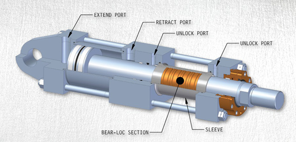
Because load-holding valves or other components in a hydraulic circuit can fail, you need a supplementary safety accessory to prevent injuries or deaths on load-holding equipment. A mechanical locking mechanism, such as the Bear-Loc®, can be a valuable replacement or addition to any piece of load-bearing equipment. Bear-Loc® offers some major benefits, including:
· Reliability:The Bear-Loc® is a positive locking device that locks instantly and automatically when hydraulic pressure is lost accidentally or on purpose. For the person, property or equipment that"s situated under a high or heavy load, that"s a priceless, life-saving assurance.
· Durability: The key to Bear-Loc’s effectiveness is interference fit: it is composed of a rod and liners enclosed in a sleeve which forms an interference fit with the outside diameter of the rod.Because the Bear-Loc® can move freely when hydraulic pressure is applied, components do not experience wear as other locking devices do.
Given all these features, and because the Bear-Loc® does not depend on valves, moving parts or other components to obtain its positive mechanical lock, it is the most reliable, positive, fail-safe rod locking device in the industry. The Bear-Loc® can work solo or in conjunction with existing equipment to keep people, equipment and projects safe and to optimize productivity.
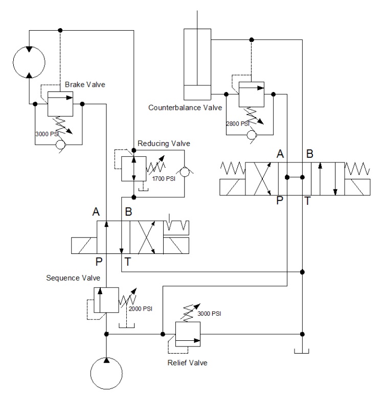
Below is a side by side comparison of a crane boom hydraulic system. The red outline in each indicates the scale of the number of components necessary to properly function for safety dependency. You can see that the Bear-Loc® can isolate safety down to dependency on itself and removes many other components that have potential to degrade or fail out of the safety equation.
In addition to the applications listed earlier, virtually any application that requires linear force can benefit from use of the Bear-Loc hydraulic locking and load holding system, and its strength and efficiency are unmatched by any other system. For example, a Bear-Loc® actuator can have pulling or holding power up to 4 million pounds and an operating pressure of up to 5000 psi. Standing or static applications can range from above and below water/subsea applications, to presses that do injection molding or forging, to compactors, to testing such as fatigue and flight or aerodynamic simulation. Mobile applications can include inspection vehicles, construction, and mining equipment, and more.
To better understand the power and safety features of the positive locking system, visit our Case Studies below of how Bear-Loc® actuators have been used by our customers.
A hydraulic valve is a mechanical device that regulates the flow of the hydraulic fluid in a hydraulic system. Hydraulic systems are typically high pressure systems, ranging from 200 Bar averaging 700 Bar upwards. This means they have to be constructed from materials that can withstand these high pressures. The methods of controlling these valves are also vast. They can be controlled physically and mechanically with electrical actuation, hydraulics, and pneumatics.
Throttling flow control is when the size of the path of the fluid is adjusted so that one can vary the flow rate. In the image depicted above, varying the cross-sectional area across the valve will help vary the flow rate. Bernoulli’s principle explains this the best.
In Bernoulli’s tapered tube depicted below, varying the diameter of the pipe from d1 to d2 will increase the velocity of the fluid running through it (V1 < V2) whether the pipe is inclined or not. Increasing the tube’s velocity means the flow rate has also been increased, as shown before. So any mechanism that will vary the cross-sectional area across the valve will effectively vary the flow rate.
It will consist of a variable orifice and a mechanism that compensates for pressure loss. The fluid will flow a path as illustrated above. It enters through an inlet whose size is varied by the pressure compensator. In this example, the pressure compensator is a compensator spool. The compensator spool is spring loaded such that the resultant force from the spring, the hydraulic load and the incoming fluid will position it to open the inlet to just the right size to maintain a constant volumetric flow rate even with pressure drops in the system.
A variation of pressure compensated flow control valve is a temperature compensated flow control valve. This variation comes because sometimes the temperature of operation may rise such that set tolerances in orifices will become inaccurate. Temperature compensators are installed to cater to these variations.
This is the most basic method of fluid flow control. It consists of a drilled hole in what acts as a passage on an otherwise blocked fluid passage. When employed for flow control, it is usually put in series with the hydraulic pump.
A common adjustable flow control valve is a priority valve. Priority valves will switch flow to only a required outlet at a given time. For instance, if the pressure in a system drops to a certain extent, the priority valve will block other outlets just to supply the crucial outlet. It achieves this by a spring load that responds depending on the pressure applied.
In a hydraulic system, these valves are used to maintain or adjust the flow rate of the hydraulic fluid. They usually have a means to adjust the flow rate. This is usually an opening or port that is able to change the flow area and by altering that flow area, it then affects the flow rate.
A typical example would be controlling the speed of extending or retracting a hydraulic cylinder. It can sometimes be on hydraulic motors or any other hydraulic actuator. The speed of operation is directly related to the flow rate of the hydraulic fluid.
Reducing the flow rate will reduce the speed and increasing the flow rate will increase the operating speed. A greater flow rate equals a greater force acting on the piston, which also means a greater speed at which the cylinder is retracting or extending.
Flow control valves vary depending on the principle method they employ to alter flow rate. Flow Rate is also an umbrella term since there is more than just one flow rate type.
Since the flow control valves basically regulate the amount of fluid that passes through the valve per unit time, all flow control valves can be used for all types of flow rates. They vary by the mechanism that is employed to alter the flow rate. For example:
So any given flow control valve will operate using a specific mechanism to achieve a certain principle method that regulates the flow rate. The principle mechanism is the science concept that if employed, the flow control will be varied. The mechanism is the tool that you employ to achieve the scientific concept.
Ball valves use a mechanism of a ball that has holes in it. Anytime the holes align an input and an output, hydraulic fluid will flow in that path. As such, there are several ball valve configurations. These configurations vary with the number of inputs and outputs are linked. They can be two way, three way, or four way ball valves.
In a 2-way ball valve, the flow is just between one input and one output. Turning the ball perpendicular to the flow direction will block out the passage completely. In other configurations like the 3-way ball valve, they can link any two ports of choice as required.
Ball valve mechanisms are used as “Switches” to shut out or open the flow. They can also be used as throttle valves when you turn them only partially but they are not well recommended for throttling.
The needle pin valve is used to control flow rates with high accuracy in low pressure applications. They are used to control flow rate, especially in pressure compensated flow control.
Needle valves work with a plunger that sits on a tapered orifice to shut off the flow. Opening and closing the flow is achieved by lifting the plunger.
(A) Is the handle that is fixed to the plunger, which can also be called a stem (F). As the handle is turned, the plunger will move up and down the threads (C) while the Locknut (B) will stop it from fully unscrewing. When the plunger comes down, the tapered end or stem (I) will sit on the valve seat and that fully seals the (H) orifice. G is an inlet port, (D) is the Bonnet, and (E) is the valve housing.
Butterfly valves are a very affordable means of flow control. They are also lightweight and the disk material comes in vast materials to cater to different hydraulic fluid properties. They can be used to shutout flow as well as to throttle flow.
Pressure-control valves as their name suggests are used to regulate the fluid pressure in a hydraulic system. This is done either by making sure the system pressure does not exceed a certain set point.
They keep the system pressure below a set level. They can be used to sustain upstream or downstream pressure from the valve. They also serve as protection to the equipment against pressure spikes or pulses.
Many fluid power systems work within a set pressure limit. These limits or ranges are a function of the generated forces required to do the work by the actuator. If these are left unmonitored, there can be excessive damage to the equipment. Relief valves chip in to help safeguard to prevent machine damage and operator damage.
The pressure at which a relief valve will start to allow flow to pass is called the cracking pressure. The difference between the current pressure in the system and the cracking pressure is called pressure differential or pressure override.
The direct acting relief valve will have a poppet ball that is directly exposed to the pressure in the system on one end. On the other end it is connected to a spring that pushes it against the system pressure. When a direct acting valve is a normally closed one, the force exerted by the spring will be greater than that of the system.
The spring can also be adjusted in length and thus the cracking pressure can be adjusted on these valves. When the system pressure surges that it becomes greater than the force from the spring, the fluid will unseat the ball such that it opens the flow to let excess fluid flow out until the system pressure is in the accepted range.
For applications where huge flows need to be relieved but using a small pressure override or small pressure differential, pilot operated relief valves are used.
The valve works in 2 different stages. The first is called the pilot stage. This is where a small relief valve (depicted as a rod with piston above) is moved so that it actuates the main relief valve (depicted with spring above).
The main relief valve acts as normally closed, especially if the system’s pressure is below that of the force exerted by the main valve spring. It must be noted that the main relief valve is exposed to pressure at both its ends with the front having less surface area in contact with the fluid than the back.
This difference in the surface area will mean that a rise in the system fluid pressure will be multiplied on the smaller surface area (pressure is inversely proportional to the area). This allows the main relief valve to open and empty excess fluids into the tank and thus subside the otherwise surging pressures.
In hydraulic systems, for regulating secondary lower pressure, pressure reducing valves are used. These valves are normally open and they are also two way valves that shut off the flow when subjected to unwanted downstream pressure.
This pressure reducing valve restricts the pressure in the secondary circuit (the circuit connected to the outlet) without paying heed to the main circuit’s pressure changes. This valve generally acts like the opposite of a pressure relief valve. It will not sense the pressure from the inlet like the pressure relief valve, but rather it will sense the pressure downstream, which is the pressure at the outlet.
In the picture above, as the pressure increases in the secondary circuit, a hydraulic force acts on area A of the valve, thus closing it partially. The spring’s force opposes the hydraulic force such that only sufficient oil flows past the valve to supply the secondary circuit at the preferred pressure. The spring setting is also adjustable.
When outlet pressure equals that of the valve setting, the valve closes. However, a small quantity of the oil bleeds from the low-pressure side of the valve. This frequently happens through an orifice in the spool, then through the spring chamber, and finally to the reservoir.
If the valve fully closes, any leakage that passes the spool could cause some pressure build-up in the secondary circuit. To escape this, a bleed passage to the reservoir keeps it opened slightly, avoiding a rise in downstream pressure above the valve setting. The drain passage returns leakage flow to the tank.
Constant-pressure-reducing valves will give off a stable pre-set pressure, irrespective of main circuit pressure, provided that the pressure in the main circuit is greater than that in the secondary.
These valves will balance the secondary circuit pressure with the force exerted by an adjustable spring that tries to open the valve. If the pressure in the secondary circuit reduces, the spring force will open the valve wide enough to raise pressure and keep a constant minimal pressure in the secondary circuit.
This valve operates by balancing the force applied by the pressure in the main circuit against the sum of the forces applied by secondary circuit pressure and the spring. Since the pressurized areas on both sides of the poppet are equal, the spring exerted a fixed reduction.
The spool is a pilot-operated, pressure-reducing valve that has balanced hydraulic pressures from downstream pressure at both ends. A light spring keeps the valve open. A small pilot relief valve will relieve the hydraulic fluid to the tank when reduced pressure reaches the pilot valve’s spring setting. This fluid flow causes a drop in the pressure across the spool. The pressure differential then shifts the spool toward its closed position against the light spring force.
The pilot valve only relieves enough fluid to position the main valve spool or poppet so that flow through the main valve equals the flow requirements of the reduced pressure circuit. When flow is no longer required in the low-pressure circuit during a portion of the cycle, the main valve closes. The high-pressure fluid leaking into the reduced-pressure section of the valve will then return to the reservoir through the pilot-operated relief valve.
In hydraulic circuits with more than one actuator, it is common to drive the actuators, such as the hydraulic cylinders, in a definite order or sequence. This outcome can sometimes be achieved by sizing cylinders according to the load they must be moving.
In many installations, the limitations in space and the force requirements govern the cylinder size required to do the job. In such scenarios, sequence valves can be utilized to actuate the cylinders in the required order.
Sequence valves are normally closed and 2-way valves. They control the sequence in which several functions in a circuit have to occur. They bear a resemblance to direct-acting relief valves but their spring chambers are usually drained externally to the reservoir, unlike internally to an outlet port, like in the case of the relief valve.
A sequence valve typically allows the pressurized fluid to flow to a second path only after an earlier priority path or duty has been concluded and satisfied. When normally closed, a sequence valve permits the hydraulic fluid to flow freely to the primary circuit, to do its first intended function until it reaches the valve’s pressure setting.
When the main function is satisfied, the pressure in the primary circuit will rise and then it is sensed in the pressure-sensing channel. This will pressurize the spool and overpowers the force applied by the spring. The spring becomes compressed, the valve spool moves, then hydraulic oil flows to the secondary circuit.
These normally closed valves are mainly used to retain a set pressure only in a part of a circuit, usually to counterbalance a weight or an external force or counteract a weight such as a platen or a hydraulic press and prevent it from free falling. The valve’s main port is directly linked to the hydraulic cylinder rod end. Then the secondary port is linked to the directional control valve. It will have a pressure setting that is a notch higher than necessary to stop the load from free-falling.
The Counterbalance valve will stop the hydraulic fluid flow from its inlet port to its outlet port until the pressure of the inlet port overpowers the spring force. When the pressurized fluid flows into the hydraulic cylinder cap, the cylinder extends, thus increasing the pressure in the rod end. Ultimately this will shift the main spool in the counterbalance valve. This then creates a path that allows the fluid to flow through the secondary port, leading to the directional control valve and finally to the reservoir. As the load gets raised, the check valve will open to allow the cylinder to retract freely.
If the cylinder force must be increased and backpressure must be relieved at the bottom of the stroke, then the counterbalance valve can be operated remotely. Counterbalance valves are typically drained internally. And when the cylinder extends, the valve has to open its secondary port that is connected to the reservoir. If the cylinder retracts, the check valve will always avoid the spool.
These valves are usually used to unload pumps. They control the pump output flow, (usually the output of a singled out pump in a system with many pumps) directly to the reservoir at a low pressure, after the pressure set point of the system has been reached.
The force applied by the spring keeps the valve closed. When a pilot signal, usually an external pilot signal, acting on the opposite end of the valve spool applies a force big enough to surpass that exerted by the spring, the valve spool shifts, directing the pump output to the reservoir at a low pressure.
The unloading valve is spring-loaded so it stays naturally in the closed position. When the system pressure overpowers the force of the adjustable spring, then the valve opens.
Unloading valves also come with a variation for pilot control to the main valve. A port through the main valve plunger allows the system pressure to act on both faces of the plunger.
A built-in check valve will maintain the system pressure. When system pressure drops to the set point value, the pilot valve will then close. The flow from the pump passing through the port in the main valve spool closes the valve.
Directional control valves are third on our list of main hydraulic valve classification. These valves allow fluid flow into more than one path when the fluid is also coming from multiple paths, or even one source. They have a spool inside that regulates which path is permitted to receive or give flow. The position of the spool is the determining factor on which paths will be active. They can be electronically controlled or manually controlled.
The most common directional control valve is called the 2-way valve. A 2-way valve either allows or blocks flow. A water tap is a good example of a 2-way valve. A water tap allows or stops fluid flow by manual control.
A single acting hydraulic cylinder requires supply to it and exhaust from its port to operate. This needs a 3-way valve. It will permit fluid flow to the actuator in one position and drain the fluid from it in the other position. Some 3-way valves have a 3rd position that blocks flow in all ports.
A double acting actuator needs a 4-way valve. The valve pressurizes then exhausts two ports interdependently. A 3-position, 4-way valve stops the actuator or makes it float. A 3-position, the 4-way valve is common in hydraulic handling.
Check valves are 2-port valves. The one is for fluid to enter and the other one for fluid to leave. There are multiple types of check valves made from different materials such as polymers, metal, and rubber. The most common designs comprise a swing or flap. In the swing or flap check valve, a metal disc pivots on a hinge or trunnion to prevent reverse flow. Bigger check valves are normally of the swing or flap type. Then there are spring and ball check valves. These feature a ball that mounts in an appropriately profiled seat.
Normally, the check valve closes due to the force from the action of the spring force. When the fluid is flowing and the fluid pressure is bigger than the cracking pressure, the spool will move off of its seat and then open the valve.
Duckbill check valves utilize a rubber diaphragm which creates a normally closed valve unless +ve pressure is applied. But unlike metal swing or flap check valves, rubber duckbill check valves are pretty reliable. They do not seize, rust, or bind. Rubber check valves do not have problems with mechanical wear that is associated with the metallic ones.
An important value to note in check valves is the cracking pressure, which is the minimum upstream pressure at which the valve will operate. Usually, the check valve is intended for controlling fluid flow in one direction; therefore, it can be specified for a specific cracking pressure.
This is a solenoid controlled directional valve that is used in hydraulic systems for opening, closing, or changing the direction of the flow of the liquid. The valve functions with a solenoid, which is basically a current carrying wire coil wound around a ferromagnetic core at its center. The valve consists of many chambers that are called ports. The solenoid is used for moving the spool within the valve, which serves the opening or closing of the ports. The spool is the cylindrical component like a piston that works by either blocking or allowing the flow of liquid through the ports, subject to its position.
The valve employs solenoids denoted by X and Y in the picture above. These solenoids are placed on either side of the valve for actuation. The valve comprises a cylindrical spool denoted with Z. The spool has “land” which is the larger diameter and grooves which are the smaller diameter. The land functions to block the flow, while the groove functions to allow flow through the valve.
Temperature: Choosing valve materials that can withstand the minimum and maximum temperature requirement of your use. Temperature also helps in determining valve capacity as it affects the viscosity and flow of the fluid.
Cartridge valves internally control the pressure, direction, and/or flow control of the hydraulic fluid. They are a kind of inline valves, which means they act parallel to the fluid flow, and are best used when high flow rates and non-leak control are necessary.
They are regarded as bodiless valves, as they are implanted into a cavity and do not have their own integral housing. They can act as many valve types in a single cartridge. Common arrangements include relief, sequence, pilot-operated, flow control, or counterbalance. They are light in weight, offer easy installation, are inexpensive, leak-resistant, and easy to repair.
This is also called a panel type cartridge valve. It will need additional pilot control to function. This type of valve is pressed against the manifold’s cover plate and it will hold on there.
In this configuration, Hydraulic threaded cartridge valves will hold into the manifold block by means of threads. Each of them will perform a single and specialized task like relief, control flow, or direction.
Jamming is common when used to regulate wrong fluids, this is because of suspending particles that will be trapped. In other circumstances they can even cause wear or make the valve stuck.
What function you want to control: this is what you would want the valve to achieve for your system. Either Controlling pressure, flow rate or changing direction.
How you want to control the function: would you like it to be electrically controlled, or automatically with the mechanical systems in the hydraulics or manually.
Check valves are a simple but important part of a hydraulic system. Simply stated, these valves are used to maintain the direction that fluid flows through a system. And since check valves are zero leakage devices, we can use them to lock hydraulic fluid from the cylinders. This section has been designed to help you understand how the different valves function and the strategy of where they are used in the system.
In-line check valves are classified as directional control valves because they dictate the direction flow can travel in a portion of the circuit. Because of their sealing capability many designs are considered to have zero leakage. The simplest check valve allows free flow in one direction and blocks flow from the opposite direction. This style of check valve is used when flow needs to bypass a pressure valve during return flow, as a bypass around a filter when a filter becomes clogged, or to keep flow from entering a portion of a circuit at an undesirable time.
Because of slight spool leakage on standard directional control valves, we must add a check valve to the circuit if we need to hydraulically lock a cylinder. This type of check valve is referred to as a pilot operated check valve.
Unlike a simple check valve, reverse flow is required through the valve to extend or retract the cylinder. This is accomplished by allowing pilot pressure to act on a pilot piston, thus opening the check valve and retracting the cylinder. To extend the cylinder, the check valve allows fluid to flow freely in one direction and blocks flow in the opposite direction.
Pressure Control Valves – A control valve is a valve used to control fluid flow by varying the size of the flow passage as directed by a signal from a controller. This enables the direct control of flow rate and the consequential control of process quantities such as pressure, temperature, and liquid level. Common schematics for pressure control valves:
By symbol, these valves closely resemble one another. Often only their location in the hydraulic circuit will designate what type of pressure valve they are.
A sequence valve is a normally closed pressure control valve that ensures that one operation will occur before another, based on pressure. In our clamp and drill system we want the clamp cylinder to extend completely before the drill cylinder extends. To accomplish this, we place a sequence valve just before the drill cylinder. We set the cylinder to 500 psi. This will ensure that the drill will not extend before we have reached 500 psi on the clamp cylinder.
A pressure reducing valve is a normally open pressure control valve used to limit pressure in one or more legs of a hydraulic circuit. Reduced pressure results in a reduced force being generated. A pressure reducing valve is the only pressure control valve that is normally open. A normally open pressure control valve has primary and secondary passages connected. Pressure at the bottom of the spool is sensed from the pilot line which is connected to the secondary port. Remember, a pressure reducing valve is normally open.
The illustrated clamp circuit requires that clamp cylinder B apply a lesser force than clamp cylinder A. A pressure reducing valve placed just before the clamp cylinder B will allow flow to go to the cylinder until pressure reaches the setting of the valve.
At this point, the valve begins to close off, limiting any further buildup of pressure. As fluid bleeds to the tank through the valve drain passage, pressure will begin to decay off and the valve will again open. The result is a reduced modulated pressure equal to the setting of the valve.
An unloading valve is a remotely piloted, normally closed pressure control valve that directs flow to the tank when pressure at that location reaches a predetermined level. A good example of an unloading valve application would be a High-Low system. A High-Low system may consist of two pumps; one high volume pump, the other a low volume pump. The system is designed to give a rapid approach or return on the work cylinder. The total volume of both pumps is delivered to the work cylinder until the load is contacted.
At this point the system pressure increases, causing the unloading valve to open. The flow from the large volume pump is directed back to the tank at a minimal pressure. The small volume pump continues to deliver flow for the higher-pressure requirement of the work cycle. Both pumps join again for rapid return of the cylinder. This application allows less input horsepower for speed and force requirements
The purpose of a counterbalance valve is to prevent a loaded cylinder, having potential energy, from falling (extending or retracting). Counterbalance valves may be internally piloted, externally piloted, or piloted internally as well as externally, and they may be internally or externally drained. If conditions exist that would interfere with internal draining the valve, it should be externally drained, but usually this is not necessary. Counterbalance valves are equipped with a free reverse flow check valve to allow for retraction of the cylinder.
The simplest counterbalance valve application is to support a constant induced load. In a down acting press application, the counterbalance valve would be installed at the rod end of the cylinder to control return oil flow. This would prevent the press platen from dropping. Pilot pressure to open an internally piloted counterbalance valve would be set approximately 100 psi above the pressure of the rod end of the cylinder caused by the weight of the platen. In order for the platen to be lowered (and powered down), the pressure at the cap end of the cylinder would have to be sufficient to generate 100 additional psi at the rod end of the cylinder. Thus, 100 psi added to the pressure generated by the weight of the platen would open the counterbalance valve and allow the platen to lower smoothly.
One disadvantage of the counterbalance valve shown in the circuit in Figure 1-13 is that back pressure on the cap side of the cylinder limits the effective force developed by the cylinder. In order to achieve full force from the cylinder, the back pressure must be relieved from the cap side of the cylinder.
This is easily achieved by using a counterbalance valve that includes an external pilot. Counterbalance valves that include an external pilot in addition to the internal pilot are called holding valves, over center valves, load control valves, or motion control valves by some manufacturers. After the cylinder has stalled against the load, the external pilot will fully open the counterbalance valve, allowing the pressure in the cap end of the cylinder to fall to virtually zero psi.
Counterbalance valves may prevent a loaded cylinder from falling. Pilot check valve circuits also hold loaded cylinders in place. Both types of circuits have unique applications. Counterbalance valves may be leak-free. For example, manufacturers commonly give the leakage rates across a counterbalance spool in drops per minute. If a cylinder must be locked in place with a valve that allows no leakage across the spool, the valve must be designed to do so.
Counterbalance valves may also incorporate external piloting for smoother, “non hunting” performance. When the manufacturer utilizes


 8613371530291